

R6
PASSIVE STUDIO MONITORS
UUSSEERR GGUUIIDDEE
Warning: To reduce the risk of fire or electric shock, do not
expose this unit to rain or moisture.
The lightning flash with an arrowhead symbol within an equilateral
triangle, is intended to alert the user to the presence of uninsulated
dangerous voltage within the product’s enclosure that may be of
sufficient magnitude to constitute a risk of electric shock to persons.
The exclamation point within an equilateral triangle is intended to
alert the user to the presence of important operating and
maintenance (servicing) instructions in the literature accompanying
the product.
Do not place this unit on an unstable cart, stand or tripod, bracket
or table. The unit may fall, causing serious injury to a child or adult
and serious damage to the unit. Use only with a cart, stand, tripod,
bracket or table recommended by the manufacturer or sold with
the unit. Any mounting of the device on a wall or ceiling should
follow the manufacturer’s instructions and should use a mounting
accessory recommended by the manufacturer.
An appliance and cart combination should be moved with care.
Quick stops, excessive force and uneven surfaces may cause the
appliance and cart combination to overturn.
Read and follow all the safety and operating instructions before
connecting or using this unit. Retain this notice and the owners
manual for future reference.
All warnings on the unit and in its operating instructions should be
adhered to.
Do not use this unit near water; for example, near a bath tub,
washbowl, kitchen sink, laundry tub, in a wet basement or near a
swimming pool.
The unit should be installed so that its location or position does not
interfere with its proper ventilation. For example, it should not be
situated on a bed, sofa, rug or similar surface that may block the
ventilation openings; or placed in a built-in installation, such as a
bookcase or cabinet, that may impede the flow of air through its
ventilation openings.
The unit should be situated from heat sources such as radiators,
heat registers, stoves or other devices (including amplifiers) that
produce heat.
The unit should be connected to a power supply outlet only of the
voltage and frequency marked on its rear panel.
The power supply cord should be routed so that it is not likely to be
walked on or pinched, especially near the plug, convenience
receptacles, or where the cord exits from the unit.
Unplug the unit from the wall outlet before cleaning. Never use
benzine, thinner or other solvents for cleaning. Use only a soft
damp cloth.
The power supply cord of the unit should be unplugged from the
wall outlet when it is to be unused for a long period of time.
Care should be taken so that objects do not fall, and liquids are not
spilled into the enclosure through any openings.
This unit should be serviced by qualified service personnel when:
A. The power cord or the plug has been damaged; or
B. Objects have fallen, or liquid has been spilled into the unit; or
C. The unit has been exposed to rain or liquids of any kind; or
D. The unit does not appear to operate normally or exhibits a
marked change in performance; or
E. The device has been dropped or the enclosure damaged.
DO NOT ATTEMPT SERVICING OF THIS UNIT
YOURSELF. REFER SERVICING TO QUALIFIED
SERVICE PERSONNEL
Upon completion of any servicing or repairs, request the service
shops assurance that only Factory Authorized Replacement Parts
with the same characteristics as the original parts have been used,
and that the routine safety checks have been performed to
guarantee that the equipment is in safe operating condition.
REPLACEMENT WITH UNAUTHORIZED PARTS MAY RESULT IN
FIRE, ELECTRIC SHOCK OR OTHER HAZARDS.
ATTENTION
POUR …VITER LES CHOC ELECTRIQUES, INTRODUIRE LA
LAME LA PLUS LARGE DE LA FICHE DANS LA BORNE
CORRESPONDANTE DE LA PRISE ET POUSSER JUSQUíAU
FOND.
CAUTION
TO PREVENT ELECTRIC SHOCK, MATCH WIDE BLADE OF
PLUG TO WIDE SLOT FULLY INSERT.
If an indoor antenna is used (either built into the set or installed
separately), never allow any part of the antenna to touch the metal
parts of other electrical appliances such as a lamp, TV set etc.
CAUTION
POWER LINES
Any outdoor antenna must be located away from all power lines.
OUTDOOR ANTENNA GROUNDING
If an outside antenna is connected to your tuner or tunerpreamplifier, be sure the antenna system is grounded so as to
provide some protection against voltage surges and built-up static
charges. Article 810 of the National Electrical Code, ANSI/NFPA No.
70-1984, provides information with respect to proper grounding of
the mast and supporting structure, grounding of the lead-in wire to
an antenna discharge unit, size of grounding conductors, location
of antenna discharge unit, connection to grounding electrodes and
requirements for the grounding electrode.
a. Use No. 10 AWG (5.3mm2) copper, No. 8 AWG (8.4mm2)
aluminium, No. 17 AWG (1.0mm2) copper-clad steel or bronze
wire, or larger, as a ground wire.
b. Secure antenna lead-in and ground wires to house with stand-off
insulators spaced from 4-6 feet (1.22 - 1.83 m) apart.
c. Mount antenna discharge unit as close as possible to where lead in enters house.
d. Use jumper wire not smaller than No.6 AWG (13.3mm2) copper,
or the equivalent, when a separate antenna-grounding electrode
is used. see NEC Section 810-21 (j).
EXAMPLE OF ANTENNA GROUNDING AS PER NATIONAL
ELECTRICAL CODE INSTRUCTIONS CONTAINED IN
ARTICLE 810 - RADIO AND TELEVISION EQUIPMENT.
NOTE TO CATV SYSTEM INSTALLER: This reminder is
provided to call the CATV system installers attention to
Article 820-40 of the National Electrical Code that provides
guidelines for proper grounding and, in particular, specifies
that the ground cable ground shall be connected to the
grounding system of the building, as close to the point of
cable entry as practical.
CAUTION
RISK OF ELECTRIC
SHOCK DO NOT OPEN
ATTENTION:
RISQUE DE CHOC ELECTRIQUE
NE PAS OUVRIR
CAUTION: TO REDUCE THE RISK OF ELECTRIC
SHOCK, DO NOT REMOVE COVER (OR BACK). NO
USER SERVICEABLE PARTS INSIDE. REFER SERVICING
TO QUALIFIED SERVICE PERSONNEL.
IMPORTANT SAFETY INSTRUCTIONS
1. “An apparatus with Class I construction shall be connected to
a mains sockets outlet with protective earthing connection.”
2. “Where the mains plug or an appliance coupler is used as the
disconnect device, the disconnection device shall remain readily
operable.”
3. “1A fuse is used to US market, voltage will be set to 115V before
shipment: 500mA fuse is used to European market, voltage will
be set to 230V before shipment.”
SSaaffeettyy IInnssttrruuccttiioonnss
ii

CCoonntteennttss
CCoonntteennttss
SSaaffeettyy IInnssttrruuccttiioonnss ........................................................................................................................................................ iiii
11..IInnttrroodduuccttiioonn .................................................................................................................................................................. 11
1.1. KRK Systems Design Philosophy .............................................. 1
22.. TThhee BBaassiiccss ...................................................................................................................................................................... 22
.1. Unpacking and Visual Inspection ............................................ 2
2
.2. Panels Overview .................................................................... 3
2
2.2.1. Front Panel .................................................................. 3
2.2.2. Back Panel ................................................................... 3
2.3. Amplifier Power Requirements ................................................. 4
2.4. Connecting your Monitors ...................................................... 5
33.. PPoossiittiioonniinngg yyoouurr MMoonniittoorrss .......................................................................................................................... 66
3.1. Monitor-Room Interaction ....................................................... 6
.2. Positioning your Monitors ....................................................... 6
3
3.2.1. Two - Channel Setup .................................................... 7
3.2.2. Subwoofer Setup .......................................................... 8
3.2.3. 5.1 Channel Surround Setup ......................................... 8
44.. TTrroouubblleesshhoooottiinngg .................................................................................................................................................... 1100
55.. SSppeecciiffiiccaattiioonnss .......................................................................................................................................................... 1122
-- SSPPAANNIISSHH
-- FFRREENNCCHH
-- GGEERRMMAANN
version (page 13)
version (page 26)
version (page 39)
iii

11.. IInnttrroodduuccttiioonn
11.. IInnttrroodduuccttiioonn
KRK Systems is the most dedicated monitor company in the world, and we are
hrilled you have joined our ever-growing family of loyal customers.
t
Congratulations!
The R6 is the ultimate passive solution in the new Generation 2 RoKit Studio
Monitor Series from KRK Systems. For years, the RoKit Series has been one of
the most popular choices for accurate monitoring, from project-studios to
top-notch music production and post-production venues. Now, the R6 provides
a new standard in passive monitoring with better performance and accuracy,
raising the bar once again. True, this is a lofty claim for this next generation KRK
series, considering KRK has always been the standard, but it is a fact.
To properly operate your new R6 monitors, we encourage you to invest a few
minutes and read this User Guide.
Thank you for choosing KRK and enjoy your R6s!
11..11 KKRRKK SSyysstteemmss DDeessiiggnn PPhhiilloossoopphhyy
OOuurr FFooccuuss iiss YYoouurr MMiixx
At KRK, our focus has always been to make the most accurate studio monitors
vailable at any price.
a
We do not offer PA gear, mixers, or motorcycles – just the tools you need to
deliver a great mix. From the legendary Exposé Series, to VXT, to the new RoKit
Generation 2 series – we really know recording monitors.
We do not add sonic characteristics like some other manufacturers that make
their monitors appear to provide more SPL, or add low frequencies that demo
well in the store. No smoke and mirrors here. Just 100% pure KRK!
When you use a KRK monitor, you can be confident that your mixes will
translate well to the wide variety of playback conditions that can occur in the real
world. We want your audio mixes to sound good everywhere – not just in your
studio!
So enough about why we do the things we do. Let’s read the basics…
1

22.. TThhee BBaassiiccss
22..11 UUnnppaacckkiinngg aanndd VViissuuaall IInnssppeeccttiioonn
Before packing and shipping, your R6 monitors have been carefully inspected
d tested by the KRK team. However, after unpacking your monitors, please
an
carefully inspect them for exterior damage and immediately report any
physical damage during transit to your shipping carrier.
Please read the included Warranty Card and call KRK Customer Service at
(954) 316-1580 before sending your product to us. In some cases, our team
can resolve your problem immediately, avoiding down time due to shipping
delays. However, if Customer Service determines that a repair is needed; a
Return Material Authorization (RMA) number will be provided to you. After you
have obtained the RMA, you can return the R6s to the dealer where they were
purchased, or sent them directly to KRK Systems.
NNootteess
- For the fastest and safest product return to KRK Systems, please use
he original shipping boxes and packaging materials. KRK Systems
t
cannot be responsible for any damages incurred during the
shipping process due to poor or inadequate packing. Please
remember to insure your shipment!
- If your monitor is out of warranty and you would like to obtain a quote
before repairing your product, please include a note with your contact
information on it and we will contact you with a service quote. Service
will be performed once your method of payment has been
established and approved.
2

22.. TThhee BBaassiiccss
22..22 PPaanneellss OOvveerrvviieeww
22..22..11 FFrroonntt PPaanneell
22..22..22 BBaacckk PPaanneell
(Figure 1)
Figure 1
(Figure 1.1)
Figure 1.1
3

22.. TThhee BBaassiiccss
Th
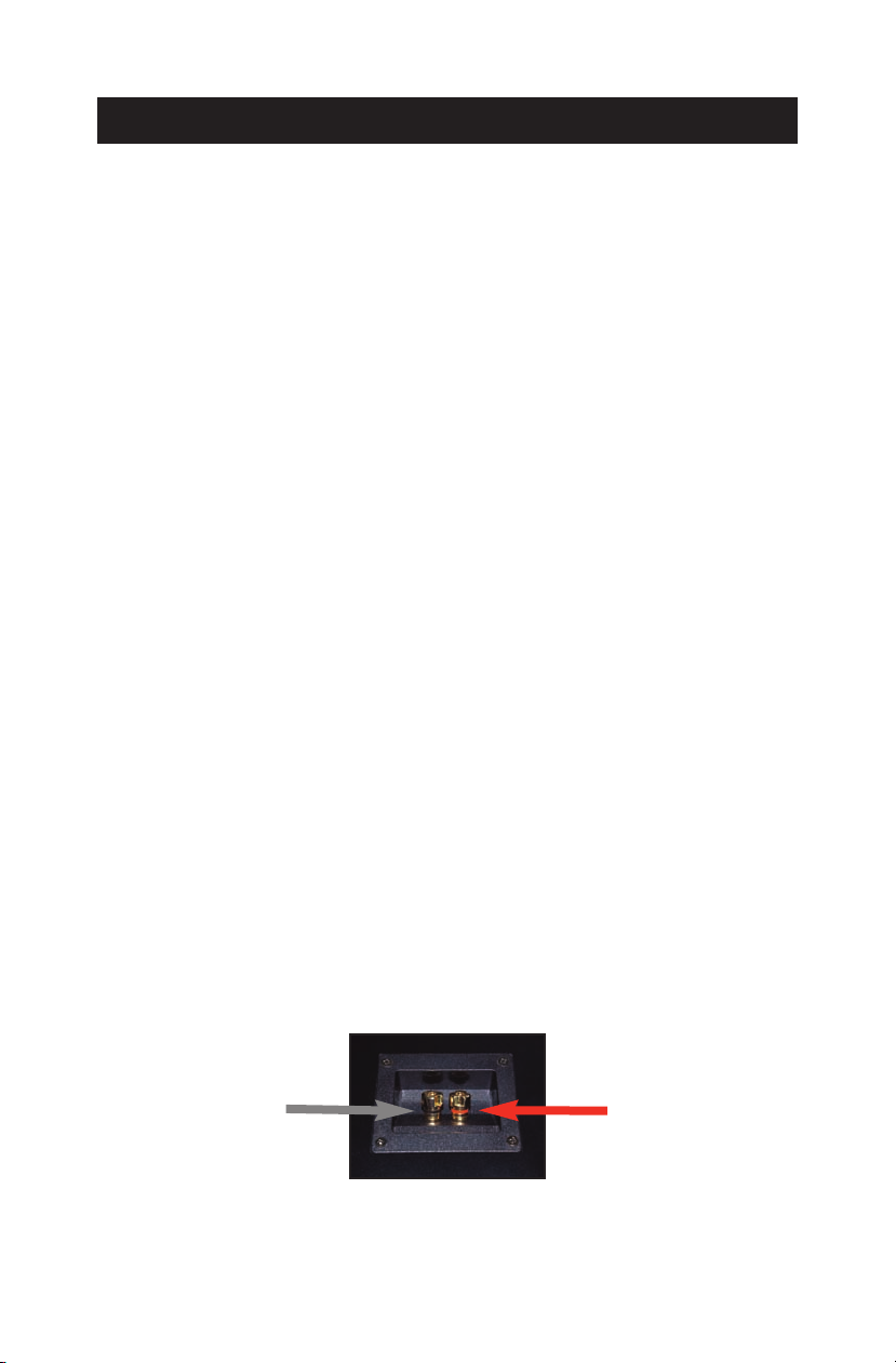
e R6 monitors use 5-way binding posts to connect to your amplifier.
(Figure 2)
Figure 2
This allows you to use a variety of different connections - ranging from bare
copper wire to lugs to banana plugs. Any of these types of cable ends will make
a good connection, but banana plugs will allow for quick disconnect whenever
necessary and eliminate the problem of stray strands of copper between the
terminals. On the amplifier side, use whatever type of end fits your power
amplifier; typically bare wire, ¼" TS plugs, lugs, or banana plugs.
NNoottee
Use unshielded cables to connect your amplifier to your speakers.
f you are not sure if you have unshielded cables, contact your local
I
music dealer to purchase the proper cabling.
Input (Right/Left), (+/-). Standard 5-way binding posts for accepting signal from
your power amplifier. The posts will accept wire-gauge sizes as large as 14
gauges. KRK recommends using 14 gauges for the best sonic response.
22..33 AAmmpplliiffiieerr PPoowweerr RReeqquuiirreemmeennttss
KRK recommends using power
amplifiers capable of producing 50 -100 RMS
watts per channel into 8 ohms. For best sonic results, a good rule of thumb is
to use an amplifier capable of producing more than 1½ times the recommended
power, rather than one that produces less than the recommended power. In fact,
more speakers are damaged due to under-powering than to over-powering. An
amplifier with insufficient power will create square waves when pushed beyond
the "comfortable" running range (potentially damaging the voice-coils).
4
22.. TThhee BBaassiiccss
22..44 CCoonnnneeccttiinngg yyoouurr MMoonniittoorrss
When hooking up passive (non-powered) speakers such as the R6 studio
onitors, you have several choices as to the proper type of cable. First, only use
m
heavy 14 to 18-gauge unshielded cables. Sonically, the heavier 14-gauge cable
is the best choice. Next, keep the speaker cable runs as short as possible. Just
measure the proper length, leaving a few extra feet for later adjustments and
easy access. Whenever possible, remember to use a heavy-gauge, unshielded
cable, especially for long (over 20 ft) runs.
Also, avoid light-gauge "zip cord.” Light-gauge cables of considerable length
not only rob amplifier power directly by turning it into heat, but they also reduce
the damping factor of your power amplifier, (which can cause inaccuracies in
the bass response of the speakers). Long cable runs can also introduce frequency
response irregularities into the monitor system, especially around the crossover
points where complex impedances exist.
CCaauuttiioonn
urn
t
terminals are accidentally shorted together for even a few seconds.
If it is possible, use polarized speaker wire. This type of wire has one of the
conductors marked with a ridge, color stripe, or other identifier such as
copper- and white-colored conductors. This will allow you to easily hook up the
speakers with the proper polarity, (which is very important for proper stereo
imaging and bass response). Simply use the striped, ridged, red, or otherwise
polarity-marked lead of the cable to hook to the hot (red, + or positive)
terminal of the amplifier. Hook the other end of the cable to the red terminal on
the monitor cabinet. Repeat using the black (negative) terminal of the amplifier
being hooked to the black terminal of the speaker cabinet. Make sure there are
no stray strands of copper poking out that might short to the opposite terminal.
(Figure 2.1)
Before to start with the following “hookup procedure,” please
Off
the amplifier. Some amplifiers will self-destruct if their output
-
Figure 2.1
5
+

33.. PPoossiittiioonniinngg yyoouurr MMoonniittoorrss
33.. PPoossiittiioonniinngg yyoouurr MMoonniittoorrss
33..11 MMoonniittoorr--RRoooomm IInntteerraaccttiioonn
The close-field monitor, by definition, reduces room interaction. This can be
ompared to the conventional stereo configuration or the large monitor
c
arrangement in a recording studio where sounds emanating from the monitor
or reflecting off ceilings, walls, and floors greatly affect the sound quality. By
shortening the path to the ear, the close-field monitor offers a tremendous
amount of flexibility, allowing the sound to become less susceptible to differing
room conditions. The ability to adjust the high frequency characteristics is equally
important to help compensate for room irregularities and achieve the best sound
accuracy.
A room that is heavily dampened would typically require a slight high frequency
boost. Likewise, reducing the high frequencies can alter a reverberant room.
Placing the monitor close to a rear wall, sidewall, or a corner will reinforce the
low frequencies. If you move them two to three feet away from walls and
corners, you will hear less low frequency interaction (excluding any interaction
with the mixing console).
33..22 PPoossiittiioonniinngg yyoouurr MMoonniittoorrss
Positioning your monitors corr
Typically, they should be placed so that the listening position is fully
“covered” with all monitors resting on the same horizontal plane. To test a
monitor for its imaging capability, playback a song that includes acoustic
instruments, to fully represent the entire sound spectrum.
You can adjust the angle of each monitor by listening for dead spots. Keep in
mind, changing the angle or position of a monitor will change the way that you
perceive your music. So lets analyze the following monitors’ configurations;
ectly in the studio is critical to their performance.
6
33.. PPoossiittiioonniinngg yyoouurr MMoonniittoorrss
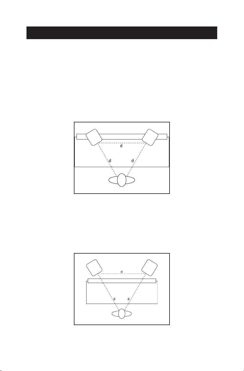
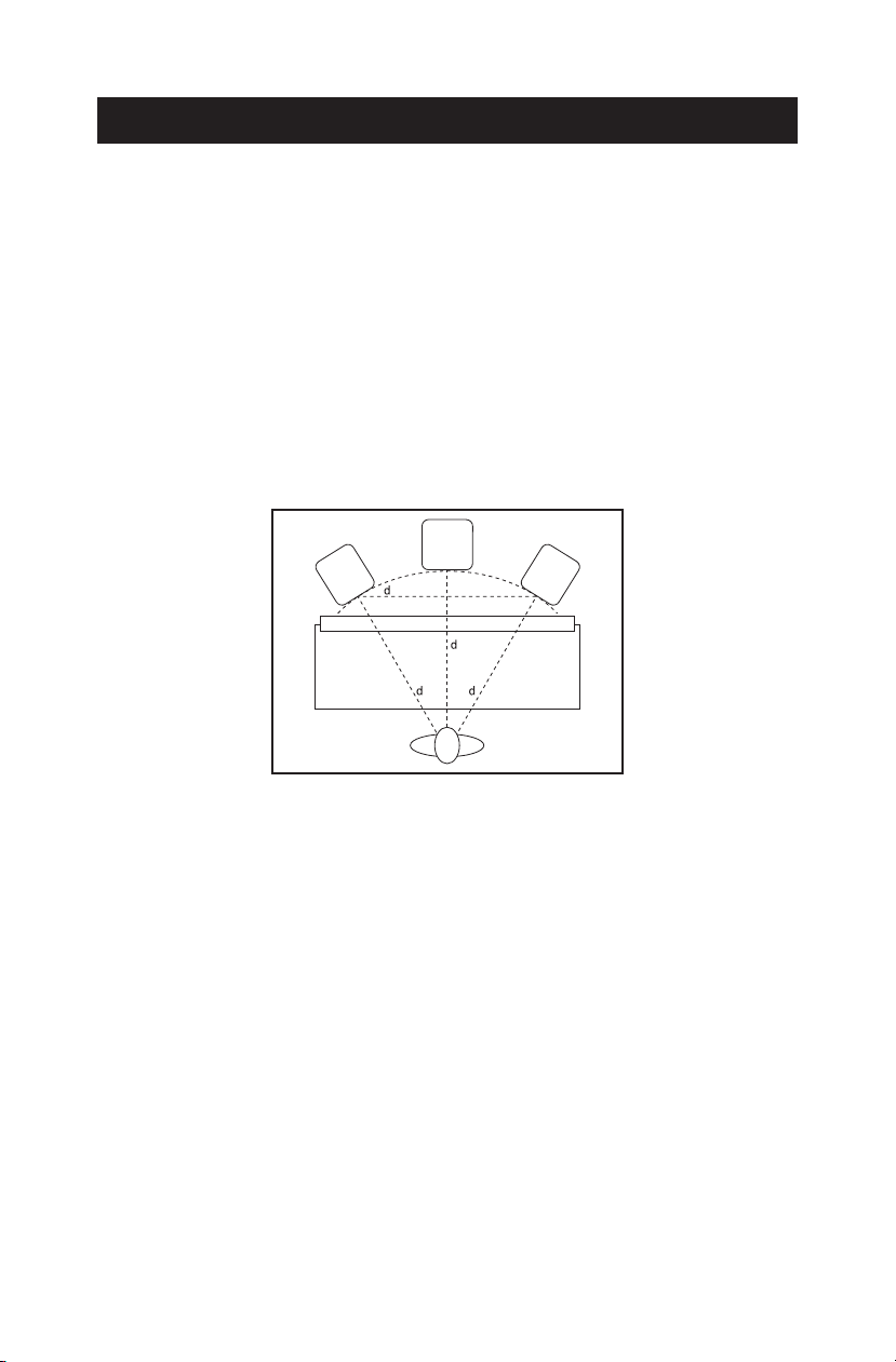
33..22..11 TTwwoo -- CChhaannnneell SSeettuupp
Near-Field Configuration
•
– In a control room situation, the monitors are often
times placed on the meter bridge or in a close-field listening position. Initial
placement starts by measuring out a simple equilateral triangle (all three sides
equal in length) with the apex at the center of the listening position as an
“overlay” for the stereo installation. In this configuration, the Left and Right
monitors are each placed at a 60° angle, equidistant from the listening position.
(Figure 3)
Figure 3
•
Mid-Field Configuration
– This configuration is similar to the close-field
configuration. It is normally used with larger monitors, or when the monitors
are too large or heavy for the meter bridge. This setup has the potential for a
larger sweet spot and better spatial imaging. Make sure that the height of the
woofer is above the height of the console. (Figure 3.1)
Figure 3.1
7
33.. PPoossiittiioonniinngg yyoouurr MMoonniittoorrss
33..22..22 SSuubbwwooooffeerr SSeettuupp
Note that KRK sub
woofers are optimized for use with KRK full range monitors.
Begin by determining the best location for your subwoofer. The optimum setup
is displayed in Figure 3.2. However, this setup may not be practical or possible
in your room. Once you have set up your monitors, listen to program material
that you know contains low frequency information. If your subwoofer has a
phase switch, adjust the subwoofer to provide the highest frequency setting
possible. Flip the switch back and forth to find the loudest setting. Then adjust
the sub’s low pass filter so that it works in conjunction with the satellite’s high
pass frequencies. When you have finished, readjust the level of the sub.
Figure 3.2
33..22..33 55..11 CChhaannnneell SSuurrrroouunndd SSeettuupp
Begin by placin
g the Left and Right front channels 30 degrees from the Center
channel and equidistant to the listening position. The Left Surround (rear) and
Right Surround (rear) channels should be placed 110 degrees from the Center
channel. Their location should also be equidistant from the listening position. The
subwoofer (Low Frequency Effects) channel is most effective when situated
directly below the Center channel. If this is not possible, place the subwoofer just
to the right or left side and below the Center channel. Ensure that the woofers
are above the height of the console. (Figure 3.3)
8

33.. PPoossiittiioonniinngg yyoouurr MMoonniittoorrss
Figure 3.3
9

44.. TTrroouubblleesshhoooottiinngg
44.. TTrroouubblleesshhoooottiinngg
- For general issues, check out these tips...
The power cord from your amplifier is plugged in.
•
• The connecting wires from your amplifier are connected to your speakers.
• All other powered components in your system are plugged in and
properly connected.
• Your main system gain control is turned up.
On
• Your signal source (for example, console, CD player, etc.) is
properly sending signal to your speakers.
- For specific problems, please read the following situations;
IIff yyoouu ccaannnnoott hheeaarr aannyy ssoouunndd......
Check the previous tips before continuing to the next steps. Then;
and
Check to see if all other audio devices using the same AC outlet are still
•
operating.
Make sure that:
• The audio source cable is plugged into both the source output and the
amplifier input.
• The gain on the amplifier is turned up.
• The signal source (for example, mixing console, workstation, CD player, etc.)
is turned up to a level that can properly send a signal to the amplifier.
10

44.. TTrroouubblleesshhoooottiinngg
• If one of the monitors is working. Exchange the cable (coming from the
mp) from the nonworking monitor to the working unit. This will
a
determine whether it is the monitor, a faulty cable, the amplifier, or some
other glitch in the audio chain.
• If the monitor is still not responding, please contact KRK Customer Service.
TThhee ssoouunndd qquuaalliittyy cchhaannggeess......
• Play some non-distorted source material at a low volume. Carefully cover
he tweeter (to block the sound) without touching the diaphragm. Is the woofer
t
producing a clean sound? If there is not a clear tonal quality or any sound
at all then the woofer probably needs to be replaced.
• Cover the woofer so you can hear mostly the tweeter. Is the tweeter
producing a clear sound? If there is not a clear tonal quality or any sound
at all then the tweeter probably needs to be replaced.
• Once you have a better idea of what may be at fault, please contact
KRK Customer Service.
TThhee mmoonniittoorr hhiisssseess,, hhuummss oorr mmaakkeess ootthheerr lloouudd nnooiisseess......
• Check the connections between the signal source and the amplifier and
hen from the amp to the monitors.
t
• All audio equipment should use the same ground point. Check all other
devices using the same AC output in the building like dimmers, neon
signs, TV screens, and computer monitors. These devices should not be
using the same circuit.
To contact us, please visit the following page:
http://www.krksys.com/contact.php
11
55.. SSppeecciiffiiccaattiioonnss
55.. SSppeecciiffiiccaattiioonnss
IImmppeeddaannccee
SSeennssiittiivviittyy
TTwweeeetteerr
WWooooffeerr
PPoowweerr HHaannddlliinngg ((RRMMSS))
RReeccoommmmeennddeedd AAmmpplliiffiieerr PPoowweerr
FFrreeqquueennccyy RReessppoonnssee
DDiissttoorrttiioonn
CCrroossssoovveerr
IInnppuutt CCoonnnneeccttiioonnss
DDiimmeennssiioonnss ((HH xx WW xx DD))
WWeeiigghhtt
8 ohms
87 dB @ 1 m / 1 W
Shielded, 1 inch soft dome
6” Aramid Glass Fiber
100 W
50 W -150 W (RMS) (8 ohms)
49 Hz-20 kHz, ±2 dB
<1% 1 W
2.5 kHz, 2nd order
5-Way Gold Plated Binding Posts
13” x 10” x 10.9”
33.02 cm x 25.40 cm x 27.68 cm
19.62 lbs
8.89 kg
12

CCoonntteenniiddoo
CCoonntteenniiddoo
11.. IInnttrroodduucccciióónn .............................................................................................................................................................. 1144
1.1. Filosofía de diseño de KRK Systems ........................................ 14
22.. LLooss eelleemmeennttooss bbáássiiccooss .................................................................................................................................... 1155
2
.1. Desembalaje e inspección visual ............................................ 15
.2. Resumen de los paneles ........................................................ 16
2
2.2.1.Panel frontal ................................................................ 16
2.2.2.Panel posterior ............................................................. 16
2.3. Requisitos del amplificador de potencia .................................. 17
2.4. Conexión de los monitores .................................................... 18
33.. PPoossiicciioonnaammiieennttoo ddee llooss mmoonniittoorreess .................................................................................................... 1199
3.1. Interacción entre monitor y habitación .................................... 19
.2. Posicionamiento de los monitores ........................................... 20
3
3.2.1. Configuración con dos canales .................................... 20
3.2.2. Configuración del subwoofer ....................................... 21
3.2.3. 5.1 Configuración de canales surround ........................ 22
44.. PPrroobblleemmaass yy ssoolluucciioonneess ................................................................................................................................ 2233
55.. EEssppeecciiffiiccaacciioonneess ..........
.......................................................................................................................................... 2255
-- EENNGGLLIISSHH
-- FFRREENNCCHH
-- GGEERRMMAANN
ersion (page iii)
v
v
ersion (page 26)
ersion (page 39)
v
13

11.. IInnttrroodduucccciióónn
11.. IInnttrroodduucccciióónn
KRK Systems es la compañía de monitores más dedicada del mundo, y nos
ncanta que se haya incorporado a nuestra siempre creciente familia de clientes
e
leales. ¡Felicitaciones!
El R6 es la máxima solución pasiva en la nueva Serie de Monitores de Estudio
Rokit Generation 2 de KRK Systems. Durante muchos años, la Serie RoKit ha
sido una de las opciones más populares para un monitoreo preciso, desde
estudios de proyectos hasta las instalaciones de producción y posproducción de
música de más alto nivel. Ahora, el R6 provee un nuevo estándar de monitoreo
pasivo que mejora el rendimiento y la precisión, aumentando una vez más el
nivel de referencia. Es verdad, esta es una afirmación osada para esta serie
KRK de próxima generación, teniendo en cuenta que KRK siempre ha sido el
estándar, pero es un hecho.
Para operar correctamente sus nuevos monitores R6, le recomendamos invertir
unos pocos minutos y leer este Manual del Usuario.
¡Gracias por elegir a KRK y esperamos que disfrute de sus R6!
11..11 FFiilloossooffííaa ddee ddiisseeññoo ddee KKRRKK SSyysstteemmss
NNooss ccoonncceennttrraammooss eenn ssuu mmeezzccllaa
En KRK, siempre nos hemos concentrado en fabricar los monitores de estudio
recisos, independientemente del precio.
más p
No ofrecemos equipos de altavoces públicos, mezcladoras ni motocicletas, sólo
las herramientas que usted necesita para obtener una excelente mezcla. Desde
la legendaria Serie Exposé, pasando por VXT, hasta la nueva serie RoKit
Generation 2, realmente sabemos de monitores de grabación.
No agregamos características sónicas como otros fabricantes que
aparentemente hacen que sus monitores parezcan brindar más SPL, o agregan
bajas frecuencias que suenan bien en la tienda. Aquí no hay ningún truco.
¡Solamente oro puro de KRK!
Cuando usted usa un monitor KRK, puede tener
la confianza de que sus mezclas se trasladarán bien a la amplia gama de
situaciones de reproducción que pueden ocurrir en el mundo real.
14

22.. LLooss eelleemmeennttooss bbáássiiccooss
¡Queremos que sus mezclas de audio suenen bien en todas partes, no
olamente en su estudio! Pero ya basta de hablar de por qué hacemos lo que
s
hacemos. Leamos lo básico...
22.. LLooss eelleemmeennttooss bbáássiiccooss
22..11 DDeesseemmbbaallaajjee ee iinnssppeecccciióónn vviissuuaall
Antes de empacar y e
nviar sus monitores R6, los mismos han sido
inspeccionados y probados cuidadosamente por el equipo de KRK.
Sin embargo, después de desempacar los monitores, inspecciónelos
cuidadosamente para ver si hay daños exteriores, e informe inmediatamente al
transportador de cualquier daño físico sufrido por la mercancía en tránsito.
Por favor lea la Tarjeta de Garantía adjunta y llame al Servicio al Cliente de KRK
al (954) 316-1580 antes de enviarnos su producto. En algunos casos, nuestro
equipo puede resolver su problema de inmediato, evitando así la pérdida de
uso del equipo debido a las demoras del envío. Sin embargo, si el Servicio al
Cliente determina que se requiere una reparación, se le dará a usted un número
de Autorización de Devolución de Material (RMA). Una vez que haya obtenido
la RMA, puede devolver los R6 al concesionario donde los compró, o enviarlos
directamente a KRK Systems.
NNoottaass
- Para obtener la devolución más rápida y segura a KRK Systems,
tilice las cajas y materiales de embalaje originales. KRK Systems no
u
se puede hacer responsable de los daños ocurridos durante el
proceso de envío a causa de un embalaje inadecuado. ¡Y no se
olvide de asegurar su envío!
Si la garantía de su monitor se ha vencido y quiere obtener
-
una estimación de precio antes de reparar su producto, incluya
una nota con sus datos de contacto y nos comunicaremos con
usted para darle un precio de servicio. Una vez que su método
de pago haya sido establecido y aprobado, se llevará a cabo
el servicio.
15

22.. LLooss eelleemmeennttooss bbáássiiccooss
22..22 RReessuummeenn ddee llooss ppaanneelleess
22..22..11 PPaanneell ffrroonnttaall
(Figura 1)
22..22..22 PPaanneell ppoosstteerriioorr
Figura 1
igura 1.1)
(F
Figura 1.1
16

22.. LLooss eelleemmeennttooss bbáássiiccooss
Los monitores R6 usan conectores múltiples de 5 vías para la conexión a su
plificador (Figura 2).
am
Figura 2
Esto le permite usar distintas conexiones, desde alambre de cobre desnudo
hasta lengüetas (lug) o enchufes tipo banana. Cualquiera de estas terminaciones
de cables ofrecerá una buena conexión, pero los enchufes tipo banana
permiten desconectar rápidamente cuando sea necesario y eliminar el
problema de las hebras de cobre deshilachadas entre los terminales. Del lado
del amplificador, use el tipo de terminación que se adapte a su amplificador de
potencia, típicamente alambre desnudo, enchufes TS de ¼", lengüetas o
enchufes tipo banana.
NNoottaa
Use cables sin camisa para conectar el amplificador a sus altavoces.
Si
no está seguro de tener cables sin camisa, consulte a su tienda local de
música para comprar los cables adecuados.
Entrada (Derecha/Izquierda), +/-. Conectores múltiples estándar de 5 vías
para aceptar la señal del amplificador de potencia. Los postes aceptan calibres
de alambre de hasta 14. KRK recomienda usar alambres de calibre 14 para
obtener la mejor respuesta sónica.
22..33 RReeqquuiissiittooss ddeell aammpplliiffiiccaaddoorr ddee ppootteenncciiaa
KRK recomienda usar amplificadores de potencia capaces de generar 50 a
vatios (RMS) por canal en 8 ohmios. Para obtener los mejores resultados
100
sónicos, una buena regla práctica es usar un amplificador capaz de generar
más de 1 vez y media la potencia recomendada, en lugar de usar uno que
genere menos de la potencia recomendada. De hecho, los altavoces se dañan
más a menudo debido a la potencia demasiado baja que a la demasiado alta.
17

22.. LLooss eelleemmeennttooss bbáássiiccooss
Un amplificador con potencia insuficiente crea ondas cuadradas cuando se lo
mpuja más allá del rango “cómodo” de funcionamiento (pudiendo dañarse las
e
bobinas de voz).
22..44 CCoonneexxiióónn ddee llooss mmoonniittoorreess
Cuando conec
monitores de estudio R6, usted tiene varias opciones en cuanto al tipo adecuado
de cable. En primer lugar, use únicamente cables no blindados de calibres 14
a 18. Desde el punto de vista sónico, la mejor opción son los cables más
grandes de calibre 14. Además, los cables de altavoces deben ser lo más cortos
posible. Mida la longitud apropiada, dejando unos pocos pies adicionales para
hacer ajustes posteriores y para facilitar el acceso. Siempre que sea posible,
recuerde usar un cable de calibre grande, sin blindaje, especialmente para
tramos largos (más de 20 pies).
Evite también los “cables zip” de bajo calibre. Los cables de bajo calibre y de
considerable longitud no solamente roban potencia al amplificador
directamente al transformarla en calor, sino que también reducen el factor de
amortiguación de su amplificador de potencia, lo cual puede causar
inexactitudes en la respuesta de graves de los altavoces. Los tramos largos de
cables también introducen irregularidades en la respuesta de frecuencias del
sistema de monitores, especialmente alrededor de los puntos de cruce o
crossover, donde existen impedancias complejas.
PPrreeccaauucciióónn
pague el amplificador. Algunos amplificadores se autodestruyen si sus
a
terminales de salida se cortocircuitan accidentalmente, aunque sólo sea por
unos segundos.
Si es posible, use cables de altavoces polarizados. Este tipo de alambre tiene
uno de los conductores marcado con un saliente, una raya de color u otro
identificador como conductores de color cobre y blanco, respectivamente. Esto
le permite conectar fácilmente los altavoces con la polaridad adecuada, lo cual
es muy importante para obtener una imagen estéreo y una respuesta de graves
adecuadas.
te altavoces pasivos (sin alimentación eléctrica propia) como los
Antes de iniciar el siguiente “procedimiento de conexión”
18

33.. PPoossiicciioonnaammiieennttoo ddee llooss mmoonniittoorreess
Simplemente use el conductor rayado, con un saliente o con la polaridad
arcada de otra manera, para conectarlo al terminal vivo (rojo, + o positivo)
m
del amplificador. Conecte el otro extremo del cable al terminal rojo del gabinete
del monitor. Repita el proceso usando el terminal negro (negativo) del
amplificador para conectarlo al terminal negro del gabinete del altavoz.
Asegúrese de que no haya hebras sueltas de cobre sobresaliendo, ya que esto
podría causar un cortocircuito con el terminal opuesto. (Figura 2.1)
-
Figura 2.1
33.. PPoossiicciioonnaammiieennttoo ddee llooss mmoonniittoorreess
33..11 IInntteerraacccciióónn eennttrree mmoonniittoorr yy hhaabbiittaacciióónn
El monitor de
habitación. Esto puede compararse con la configuración convencional de
estéreo o la configuración de monitores grandes en un estudio de grabación,
donde los sonidos que emanan del monitor o se reflejan en techos, paredes y
pisos afectan en gran medida a la calidad de sonido. Al acortar el camino
hacia el oído, el monitor de campo cercano ofrece una tremenda flexibilidad,
permitiendo que el sonido sea menos susceptible a las distintas características
de la habitación. La posibilidad de ajustar las características de alta frecuencia
es igualmente importante para compensar las irregularidades de la habitación
y lograr la mayor exactitud del sonido.
Una habitación con fuerte amortiguación requeriría típicamente un ligero
aumento de las frecuencias altas. Y análogamente, al reducir las altas
frecuencias se puede alterar una habitación reverberante.
campo cercano, por definición, reduce la interacción con la
+
Si se coloca el monitor cerca de una pared trasera, una pared lateral o una
esquina, se reforzarán las bajas frecuencias. Si los mueve a dos o tres pies de
distancia de paredes y esquinas, oirá menos interacción de baja frecuencia
(excluida la interacción con la consola de mezclado).
19

33.. PPoossiicciioonnaammiieennttoo ddee llooss mmoonniittoorreess
33..22 PPoossiicciioonnaammiieennttoo ddee llooss mmoonniittoorreess
El posicionami
ento correcto de sus monitores en el estudio es esencial para su
funcionamiento. Típicamente, deben colocarse de modo que la posición de
escucha esté totalmente (cubierta), con todos los monitores en el mismo plano
horizontal. Para probar la capacidad de imagen de un monitor, reproduzca
una canción que incluya instrumentos acústicos, a fin de representar plenamente
todo el espectro de sonido.
Puede ajustar el ángulo de cada monitor escuchando para detectar puntos
muertos. Tenga en cuenta que el cambio de ángulo o posición de un monitor
cambiará la forma en que usted percibe la música. Analicemos las siguientes
configuraciones de monitores:
33..22..11 CCoonnffiigguurraacciióónn ccoonn ddooss ccaannaalleess
Configuración del campo cercano
•
– En una sala de control, los monitores se
suelen colocar sobre el medidor de nivel o en una posición de escucha del
campo cercano. La ubicación inicial empieza por medir un simple triángulo
equilátero (los tres lados son iguales) con el vértice en el centro de la posición
de escucha como “overlay” para la instalación de estéreo. En esta
configuración, los monitores izquierdo y derecho se colocan en un ángulo de
60°, equidistantes de la posición de escucha. (Figura 3)
Figura 3
20

33.. PPoossiicciioonnaammiieennttoo ddee llooss mmoonniittoorreess
Configuración del campo medio
•
– Esta configuración es similar a la
configuración del campo cercano. Normalmente se usa con monitores grandes,
o cuando éstos son demasiado grandes o pesados para el medidor de nivel.
Esta configuración tiene el potencial de ofrecer un punto focal (sweet spot) más
amplio y una mejor imagen espacial. Asegúrese de que la altura del woofer esté
por encima de la altura de la consola. (Figura 3.1)
Figura 3.1
33..22..22 CCoonnffiigguurraacciióónn ddeell ssuubbwwooooffeerr
Observe que los
subwoofers KRK están optimizados para uso con monitores
KRK de gama completa. En primer lugar, determine el mejor lugar para su
subwoofer. La configuración óptima se muestra en la Figura 3.2. Sin embargo,
esta configuración puede no ser práctica o posible en su habitación. Una vez
que haya instalado los monitores, escuche material programado que sabe
contiene información de baja frecuencia. Si su subwoofer tiene un interruptor de
fase, ajuste el subwoofer para proveer el máximo valor posible de alta
frecuencia. Mueva el interruptor hacia atrás y adelante para encontrar el valor
más alto. Después ajuste el filtro de paso bajo del subwoofer de modo que
funcione en conjunto con las frecuencias de paso alto del satélite. Una vez que
haya terminado, reajuste el nivel del subwoofer.
21

33.. PPoossiicciioonnaammiieennttoo ddee llooss mmoonniittoorreess
Figura 3.2
33..22..33 55..11 CCoonnffiigguurraacciióónn ddee ccaannaalleess ssuurrrroouunndd
En primer lugar, coloque los canales frontales izquierdo y derecho a 30 grados
el canal central, y equidistantes de la posición de escucha. El canal surround
d
izquierdo (trasero) y derecho (trasero) deben colocarse a 110 grados respecto
al canal central. Su ubicación debe también ser equidistante de la posición de
escucha. El canal de subwoofer es más eficaz cuando se sitúa directamente
debajo del canal central (Figura 3.3). Si esto no resulta posible, coloque el
subwoofer apenas a la derecha o a la izquierda y debajo del canal central.
Asegúrese de que los woofers estén por encima de la altura de la consola.
Figura 3.3
22

44.. PPrroobblleemmaass yy ssoolluucciioonneess
44.. PPrroobblleemmaass yy ssoolluucciioonneess
- Para resolver problemas generales, consulte estas recomendaciones...
El cable de alimentación del amplificador está enchufado.
•
• Los alambres de conexión que vienen del amplificador están conectados a
los altavoces.
• Todos los demás componentes de su sistema están enchufados y
debidamente conectados.
• El control de ganancia principal de su sistema ha sido subido.
• Su fuente de señal (por ejemplo, consola, reproductor de CD, etc.)
está encendido y está enviando la señal correctamente a los altavoces.
- En caso de problemas específicos, lea las siguientes situaciones:
SSii nnoo ppuueeddee ooíírr nniinnggúúnn ssoonniiddoo......
Consulte las recomendaciones anteriores antes de pasar a los pasos siguientes.
uego, vea si todos los demás dispositivos de audio que usan el mismo
L
tomacorriente están aún funcionando. Asegúrese de que:
• El cable de la fuente de audio esté enchufado tanto en la salida de la
fuente como en la entrada del amplificador.
• La ganancia del amplificador esté subida.
• La fuente de señal (por ejemplo, la consola de mezclado, estación de
trabajo, reproductor de CD, etc.) esté subida a un nivel que pueda
enviar correctamente una señal al amplificador.
• Si uno de los monitores funciona. Intercambie el cable (que viene
del amplificador) del monitor que no funciona con el de la unidad que
sí funciona. Esto determinará si el problema es el monitor, o un
cable defectuoso, el amplificador u otro problema en la cadena de audio.
23

44.. PPrroobblleemmaass yy ssoolluucciioonneess
• Si el monitor sigue sin responder, póngase en contacto con el
rvicio al Cliente de KRK.
Se
LLaa ccaalliiddaadd ddeell ssoonniiddoo ccaammbbiiaa......
• Reproduzca algún material fuente no distorsionado a bajo nivel.
ubra cuidadosamente el tweeter (para bloquear el sonido) sin tocar
C
el diafragma. ¿Produce el woofer un sonido claro? Si no hay una
calidad tonal clara o si no hay sonido, probablemente sea
necesario reemplazar el woofer.
• Cubra el woofer para poder oír principalmente el tweeter. ¿Produce el
tweeter un sonido claro? Si no hay una calidad tonal clara o si no hay
sonido, probablemente sea necesario reemplazar el tweeter.
• Una vez que tenga una idea más clara del problema, póngase en
contacto con el Servicio al Cliente de KRK.
EEll mmoonniittoorr eemmiittee ssoonniiddooss ssiibbiillaanntteess,, zzuummbbiiddooss uu oottrrooss rruuiiddooss ffuueerrtteess......
• Revise las conexiones entre la fuente de señal y el amplificador, y
espués desde el amplificador a los monitores.
d
• Todos los equipos de audio deben usar el mismo punto de tierra. Revise
todos los demás dispositivos que usen la misma salida de corriente alterna
en el edificio, como atenuadores, luminosos de neón, pantallas de
televisión y monitores de computadoras. Estos dispositivos no deben usar
el mismo circuito.
Para ponerse en contacto con nosotros, visite la siguiente página:
http://www.krksys.com/contact.php
24

55.. EEssppeecciiffiiccaacciioonneess
55.. EEssppeecciiffiiccaacciioonneess
IImmppeeddaanncciiaa
SSeennssiibbiilliiddaadd
TTwweeeetteerr
WWooooffeerr
PPootteenncciiaa ((RRMMSS))
PPootteenncciiaa ddee aammpplliiffiiccaacciióónn rreeccoommeennddaaddaa
RReessppuueessttaa ddee ffrreeccuueenncciiaa
DDiissttoorrssiióónn
FFrreeccuueenncciiaass ddee ccrruuccee ((ccrroossssoovveerr))
CCoonneexxiioonneess ddee eennttrraaddaa
DDiimmeennssiioonneess
((aallttuurraa xx aanncchhoo xx pprrooffuunnddii ddaadd))
PPeessoo
8 ohmios
87 dB @ 1 m / 1 W
Blindado de 1 pulgada con
domo blando
De 6”, de fibra de vidrio-aramida
100 W
50 W -150 W (RMS) (8 ohmios)
49 Hz-20 kHz, ±2 dB
<1% 1 W
2.5 kHz, segundo orden
Conectores múltiples de 5 vías
chapados en oro
13” x 10” x 10.9”
33.02 cm x 25.40 cm x 27.68 cm
19.62 lbs
8.89 kg
25

CCoonntteennuu
CCoonntteennuu
11.. IInnttrroodduuccttiioonn ................................................................................................................................................................ 2277
1.1 Philosophie de conception de KRK Systems .............................. 27
22.. LLeess bbaasseess ...................................................................................................................................................................... 2288
.1. Déballage et contrôle visuel ................................................... 28
2
.2. Vue d'ensemble des panneaux .............................................. 29
2
2.2.1. Panneau avant ........................................................... 29
2.2.2. Panneau arrière .......................................................... 29
2.3. Puissance de l’amplificateur ................................................... 30
2.4. Connexion des moniteurs ...................................................... 31
33.. PPoossiittiioonnnneemmeenntt ddeess mmoonniitteeuurrss .............................................................................................................. 3322
3.1. Interaction moniteur-salle ...................................................... 32
.2. Positionnement des moniteurs ................................................ 33
3
3.2.1. Configuration deux canaux .......................................... 33
3.2.2. Configuration des subwoofers ...................................... 34
3.2.3. 5.1 Configuration ambiophonie des canaux .................. 35
44.. DDééppaannnnaaggee ................................................................................................................................................................ 3366
55.. SSppéécciiffiiccaattiioonnss .......................................................................................................................................................... 3388
-- EENNGGLLIISSHH
-- SSPPAANNIISSHH
-- GGEERRMMAANN
version (page iii)
ersion (page 13)
v
ersion (page 39)
v
26

11.. IInnttrroodduuccttiioonn
11.. IInnttrroodduuccttiioonn
KRK Systems
et nous sommes ravis que vous ayez rejoint notre famille en essor constant de
clients fidèles. Félicitations !
Le modèle R6 est la solution passive ultime dans la nouvelle série de moniteurs
pour studio 2 RoKit de génération 2 de KRK Systems. Depuis des années, la
Série RoKit Series est l'un des choix les plus populaires pour une surveillance
précise, des studios projets aux sites de production et de post-production de
musique de premier ordre. Désormais, le modèle R6 offre une nouvelle norme
en surveillance passive grâce à de meilleures performances et précision, élevant
la barre une fois encore. C'est vrai qu'il s'agit là d'une revendication hautaine
pour cette Série KRK de la prochaine génération compte tenu du fait que KRK
a toujours été la norme mais c'est un fait.
Pour faire correctement fonctionner ces nouveaux moniteurs R6, nous vous
encourageons à prendre quelques minutes pour lire ce Guide d'utilisation.
Merci d'avoir choisi KRK et profitez bien de vos R6 !
11..11 PPhhiilloossoopphhiiee ddee ccoonncceeppttiioonn ddee KKRRKK SSyysstteemmss
NNoouuss nnoouuss ccoonncceennttrroonnss ssuurr vvoottrree mmiixxaaggee
Chez KRK, nous
studios les plus précis disponibles à tous les prix.
est la société d'appareils de contrôle la plus spécialisée au monde
nous concentrons toujours sur la fabrication de moniteurs pour
Nous n'offrons pas de matériel de PA, de mixers ni de motos – simplement les
outils dont vous avez besoin pour obtenir un excellent mixage. Série légendaire
Exposé Series, VXT et la nouvelle Série RoKit Génération 2 – nous connaissons
vraiment les moniteurs d'enregistrement.
Nous n'ajoutons aucune caractéristique acoustique contrairement à d'autres
fabricants qui font en sorte que leurs moniteurs semblent fournir plus de niveau
de pression acoustique [SPL] ou ajoutent de basses fréquences qui font de
bonnes démos dans les magasins. Rien de factice ici. Juste du 100 % pur
KRK !
27

22.. LLeess bbaasseess
Lorsque vous utilisez un moniteur KRK, vous pouvez être sûr que vos mixages
e convertiront bien dans toute la variété de conditions de lecture susceptibles
s
d'avoir lieu dans le monde réel. Nous voulons que vos mixages audio aient un
son excellent partout – pas simplement dans votre studio ! Mais assez parlé de
la raison pour laquelle nous faisons ce que nous faisons, passons aux bases…
22.. LLeess bbaasseess
22..11 DDéébbaallllaaggee eett ccoonnttrrôôllee vviissuueell
Avant d'être emballés et expédiés, vos moniteurs R6 ont été soigneusement
ontrôlés et testés par l'équipe KRK. Néanmoins, après avoir déballé vos
c
moniteurs, veuillez soigneusement les contrôler pour tout dommage extérieur
éventuel et signaler immédiatement tout dommage matériel durant le transit à
votre transporteur.
Veuillez lire la Carte de garantie ci-jointe et appeler le Service à la clientèle
KRK en composant le (954) 316-1580 avant de nous envoyer votre produit.
Dans certains cas, notre équipe peut résoudre votre problème immédiatement,
évitant ainsi un temps d'immobilisation dû aux délais d'expédition. Néanmoins,
si le Service à la clientèle détermine qu'une réparation s'avère nécessaire, on
vous fournira un numéro d'autorisation de retour (RMA). Après avoir obtenu le
RMA, vous pouvez retourner les R6 au distributeur où ils ont été achetés ou bien
les envoyer directement à KRK Systems.
OObbsseerrvvaattiioonnss
- Pour retourner le produit le plus rapidement et le plus sûrement à KRK Systems,
euillez utiliser les cartons d'expédition et le matériel d'emballage
v
originaux. KRK Systems ne peut en aucun être responsable des dommages
encourus pendant l'expédition en raison d'un emballage médiocre
ou inadéquat. N'oubliez pas d'assurer votre expédition !
- Si votre moniteur n'est plus sous garantie et que vous souhaitiez obtenir un
devis avant de faire réparer votre produit, veuillez inclure une
note avec vos coordonnées et nous vous contacterons avec un devis
de service. Le service sera effectué une fois la méthode de
paiement établie et approuvée.
28

22.. LLeess bbaasseess
22..22 VVuuee dd''eennsseemmbbllee ddeess ppaannnneeaauuxx
22..22..11 PPaannnneeaauu aavvaanntt
22..22..22 PPaannnneeaauu aarrrriièèrree
(Figure 1)
Figure 1
igure 1.1)
(F
Figure 1.1
29

22.. LLeess bbaasseess
Les moniteurs R6 utilisent des bornes universelles pour se connecter à votre
plificateur (Figure 2).
am
Figure 2
Ceci vous permet d'utiliser une variété de connexions différentes : fil de cuivre
nu, cosses ou fiches banane. N'importe lequel de ces types de têtes de câbles
fera une bonne connexion, toutefois, les fiches banane permettront une
déconnexion rapide quand il le faut et éliminera le problème de fils effilochés
de cuivre entre les bornes. Du côté amplificateur, utilisez le type de tête
convenant à votre amplificateur de puissance ; généralement un fil nu, des fiches
TS de ¼" TS, des cosses ou des fiches banane.
RReemmaarrqquuee
am
plificateur à vos haut-parleurs. Si vous n'êtes pas sûr d'avoir des câbles
Utilisez des câbles non blindés pour connecter votre
non blindés, contactez votre distributeur local en musique pour faire l'achat
du câblage approprié.
Entrée (droite/gauche), +/-. Bornes universelles standard pour accepter le
signal de votre amplificateur de puissance. Les bornes accepteront des tailles de
calibres pour fils d'un maximum de calibre 14. KRK recommande l'utilisation
de calibres 14 pour obtenir la meilleure réponse acoustique.
22..33 PPuuiissssaannccee ddee ll’’aammpplliiffiiccaatteeuurr
KRK recommande l'utilisation d'amplificateurs de puissance capables de
roduire de 50 à100 watts (RMS) par canal en 8 ohms. Pour obtenir les
p
meilleurs résultats acoustiques, un bon principe de base est d'utiliser un
amplificateur capable de produire plus de 1½ fois la puissance recommandée
plutôt que d'en utiliser un qui produise moins que la puissance recommandée.
En fait, davantage de haut-parleurs sont endommagés par une puissance
insuffisante que par une puissance excessive.
30

22.. LLeess bbaasseess
Un amplificateur aya
quand il est poussé au-delà de sa plage de fonctionnement « confortable »
(endommageant éventuellement les bobines mobiles).
22..44 CCoonnnneexxiioonn ddeess mmoonniitteeuurrss
Lors de la connexion de haut-parleurs passifs (hors tension) tels que les
oniteurs pour studio R6, il existe plusieurs choix de type approprié de câble.
m
Tout d'abord, utilisez uniquement des câbles non blindés de calibres 14 à 18.
Sur le plan acoustique, le câble plus lourd de calibre 14 est le meilleur choix.
Ensuite, gardez le câble du haut-parleur aussi court que possible. Mesurez
simplement la bonne longueur en laissant quelques centimètres pour réglage
ultérieur et facilité d'accès. Dans la mesure du possible, n'oubliez pas d'utiliser
un câble non blindé de gros calibre, en particulier pour de longues distances
(plus de 20 pi).
Évitez également les « cordons zip » de faible calibre. Les câbles de faible
calibre de longueur considérable non seulement dérobent la puissance de
l'amplificateur directement pour le transformer en chaleur mais réduisent
également le facteur d'amortissement de votre amplificateur de puissance, (ce
qui peut entraîner des inexactitudes de la réponse des basses des haut-parleurs).
Les longues distances de câble peuvent également introduire des irrégularités de
réponse de fréquence dans le système des moniteurs, surtout à proximité des
points de traversée où existent des impédances complexes.
nt une puissance insuffisante créera des ondes carrées
AAtttteennttiioonn
euillez éteindre l'amplificateur. Certains amplificateurs s'autodétruisent si
v
leurs bornes de sortie sont accidentellement court-circuitées ensemble et ce,
même quelques secondes.
Dans la mesure du possible, utilisez du fil pour haut-parleurs polarisé. Ce type
de fil a un des conducteurs marqué d'une rayure nervurée de couleur ou d'un
autre identificateur tel que des conducteurs de couleurs cuivre et blanc. Ceci
vous permettra de facilement connecter les haut-parleurs avec la polarité
appropriée (ce qui est très important pour une imagerie stéréo et une réponse
des basses appropriées).
Avant de commencer la « procédure de connexion » suivante,
31

33.. PPoossiittiioonnnneemmeenntt ddeess mmoonniitteeuurrss
Il suffit d'utiliser la tête de câble rayée, nervurée, rouge ou autrement marquée
our polarité pour connecter à la borne chargée (rouge, + ou positive) de
p
l'amplificateur. Raccordez l'autre extrémité du câble à la borne rouge sur
l'élément du moniteur. Répétez l'utilisation de la borne noire (négative) de
l'amplificateur connectée à la borne noire de l'élément du haut-parleur. Veillez
à ce qu'aucun fil de cuivre ne sorte et ce, pour ne pas faire court-circuiter la
borne opposée. (Figure 2.1)
-
Figure 2.1
33.. PPoossiittiioonnnneemmeenntt ddeess mmoonniitteeuurrss
33..11 IInntteerraaccttiioonn mmoonniitteeuurr--ssaallllee
Le moniteur à champ proche, par définition, diminue l'interaction de salle. Ceci
ut être comparé à la configuration stéréo traditionnelle ou à l'aménagement
pe
de grands moniteurs dans un studio d'enregistrement où les sons émanant du
moniteur ou se répercutant des plafonds, murs et sols affectent considérablement
la qualité sonore. En raccourcissant la distance jusqu'aux oreilles, le moniteur
à champ proche offre une immense flexibilité, permettant au son de devenir
moins susceptible aux conditions ambiantes différentes. La capacité d'ajuster
les caractéristiques de haute fréquence est tout aussi importante pour permettre
de compenser les irrégularités ambiantes et d'obtenir la meilleure exactitude
sonore possible.
Une pièce fortement amortie exigerait généralement une légère augmentation
de haute fréquence. De même, une réduction des hautes fréquences peut altérer
une salle réverbérante.
+
Placer le moniteur près d'un mur arrière, d'une paroi latérale ou d'un angle
renforcera les basses fréquences. Si vous l'écartez de deux à trois pieds des
murs et des angles, vous entendrez moins d'interaction de basses fréquences (à
l'exclusion de toute interaction avec la console de mixage).
32

33.. PPoossiittiioonnnneemmeenntt ddeess mmoonniitteeuurrss
33..22 PPoossiittiioonnnneemmeenntt ddeess mmoonniitteeuurrss
Le positionnement correct de vos moniteurs dans le studio est essentiel à leurs
erformances. En général, ils doivent être placés de manière à ce que la position
p
d'écoute soit complètement « couverte », tous les moniteurs reposant sur le
même plan horizontal. Pour tester la capacité d'imagerie d'un moniteur, faites
jouer une chanson qui inclut des instruments acoustiques pour représenter
complètement tout le spectre sonore.
Vous pouvez ajuster l'angle de chaque moniteur en surveillant les points morts.
N'oubliez pas que modifier l'angle ou la position d'un moniteur modifiera la
manière dont vous percevez la musique. Analysons donc les configurations de
moniteurs suivantes.
33..22..11 CCoonnffiigguurraattiioonn ddeeuuxx ccaannaauuxx
Configuration de champ proche
•
– Dans une situation de salle de régie, les
moniteurs sont souvent placés sur l'indicateur de chevrotement ou dans une
position d'écoute à champ proche. Le placement initial commence par la mesure
d'un simple triangle équilatéral (les trois côtés ayant la même longueur) avec le
sommet au centre de la position d'écoute comme un « calque » de l'installation
stéréo. Dans cette configuration, les moniteurs gauche et droit sont chacun
placés à un angle de 60°, équidistant de la position d'écoute. (Figure 3)
Figure 3
33

33.. PPoossiittiioonnnneemmeenntt ddeess mmoonniitteeuurrss
Configuration de champ intermédiaire
•
– Cette configuration est semblable à
la configuration de champ proche. Celle-ci est normalement utilisée avec des
moniteurs plus larges ou lorsque les moniteurs sont trop grands ou trop lourds
pour l'indicateur de chevrotement. Cette configuration a le potentiel d'une zone
d'impact plus importante et d'une meilleure imagerie spatiale. Veillez à ce que
la hauteur du woofer soit supérieure à celle de la console. (Figure 3.1)
Figure 3.1
33..22..22 CCoonnffiigguurraattiioonn ddeess ssuubbwwooooffeerrss
Notez que les subwoofers KRK sont optimisés pour une utilisation avec les
m
oniteurs pleine gamme KRK. Commencez par déterminer le meilleur
emplacement pour votre subwoofer. La configuration optimale est illustrée à la
Figure 3.2. Toutefois, il se peut que cette configuration ne soit ni pratique ni
possible dans votre salle. Une fois les moniteurs configurés, écoutez des
émissions qui, vous en êtes sûr, comportent une information basse fréquence. Si
votre subwoofer est muni d'un commutateur de phase, ajustez le subwoofer pour
fournir le réglage de haute fréquence le plus haut possible. Faites basculer le
commutateur pour trouver le réglage le plus fort. Ajustez ensuite le filtre
passe-bas du subwoofer de manière à ce qu'il fonctionne en conjonction avec
les fréquences passe-haut de satellite. Une fois terminé, rajustez le niveau du
subwoofer.
34

33.. PPoossiittiioonnnneemmeenntt ddeess mmoonniitteeuurrss
Figure 3.2
33..22..33 55..11 CCoonnffiigguurraattiioonn aammbbiioopphhoonniiee ddeess ccaannaauuxx
Commencez par placer les canaux avant gauche et droit à 30 degrés du canal
entral et équidistants de la position d'écoute. Les canaux ambiance gauche
c
(arrière) et droit (arrière) doivent être placés à 110 degrés du canal central. Leur
emplacement doit également être équidistant de la position d'écoute. Le canal du
subwoofer (effets de basse fréquence) est le plus efficace lorsqu'il est situé
directement sous le canal central (comme l'indique la Figure 3.3). Si cela s'avère
impossible, placez le subwoofer juste à droite ou à gauche et sous le canal central.
Assurez-vous que les woofers se trouvent au-dessus de la hauteur de la console.
Figure 3.3
35

44.. DDééppaannnnaaggee
44.. DDééppaannnnaaggee
- Pour des questions d'ordre général, consultez ces conseils...
Le cordon d'alimentation de votre amplificateur est branché.
•
• Les fils de connexion de votre amplificateur sont connectés à vos haut-parleurs.
• Tous les autres composants alimentés de votre système sont branchés
et correctement connectés.
• La commande de gain de votre système principal est remontée.
• Votre source de signal (par exemple, console, lecteur CD, etc.) est sous
tension et envoie correctement un signal à vos haut-parleurs.
- Pour des problèmes spécifiques, veuillez lire les situations suivantes.
SSii vvoouuss nn''eenntteennddeezz aauuccuunn ssoonn……
Consultez les conseils précédents avant de continuer aux étapes suivantes.
e :
Ensuit
• Vérifiez que tous les autres dispositifs audio utilisant la même prise c.a.
fonctionnent toujours.
Veillez à ce qui suit :
• Le câble de source audio est branché à la fois dans la sortie de source
et l'entrée de l'amplificateur.
• Le gain sur l'amplificateur est remonté.
• La source de signal (par exemple, console de mixage, station de
travail, lecteur CD, etc.) est remontée à niveau capable d'envoyer
correctement un signal à l'amplificateur.
36

44.. DDééppaannnnaaggee
• Si l'un des moniteurs fonctionne. Échangez le câble (provenant
e amplificateur) du moniteur qui ne fonctionne pas avec le câble de celui
d
qui fonctionne et ce, pour déterminer s'il s'agit du moniteur, d'un
câble défectueux, de l'amplificateur ou de tout autre problème technique
dans la chaîne audio.
• Si le moniteur ne fonctionne toujours pas, veuillez contacter le
Service à la clientèle KRK.
LLaa qquuaalliittéé ssoonnoorree cchhaannggee......
• Faites jouer une émission de source non déformée à un volume bas.
uvrez soigneusement le tweeter (pour bloquer le son) sans toucher
Co
la membrane. Le woofer produit-il un son net ? S'il n'y a pas de qualité
tonale nette ou pas de son du tout, le woofer a probablement besoin
d'être remplacé.
• Couvrez le woofer de manière à ne pouvoir entendre que le tweeter.
Le tweeter produit-il un son net ? S'il n'y a pas de qualité tonale nette ou
pas de son du tout, le tweeter a probablement besoin d'être remplacé.
• Une fois que vous avez une meilleure idée du problème, veuillez contacter
le Service à la clientèle KRK.
LLee mmoonniitteeuurr ssiiffffllee,, bboouurrddoonnnnee oouu éémmeett dd''aauuttrreess bbrruuiittss ffoorrttss......
• Vérifiez les connexions entre la source de signal et l'amplificateur, ainsi
ue de l'amplificateur aux moniteurs.
q
• Tout le matériel audio doit utiliser le même point de mise à la terre.
Vérifiez tous les autres dispositifs utilisant la même sortie c.a. dans le
bâtiment tels que variateurs d'ambiance, enseignes au néon, écrans
de télévision et moniteurs d'ordinateurs. Ces dispositifs ne doivent pas
utiliser le même circuit.
Pour nous contacter, veuillez consulter la page suivante :
http://www.krksys.com/contact.php
37

55.. SSppéécciiffiiccaattiioonnss
55.. SSppéécciiffiiccaattiioonnss
IImmppééddaannccee
SSeennssiibbiilliittéé
TTwweeeetteerr
WWooooffeerr
PPuuiissssaannccee aaddmmiissssiibbllee ((RRMMSS))
PPuuiissssaannccee dd''aammpplliiffiiccaatteeuurr
rreeccoommmmaannddééee
RRééppoonnssee ddee ffrrééqquueennccee
DDiissttoorrssiioonn
CCrrooiisseemmeenntt
CCoonnnneexxiioonnss dd''eennttrrééee
DDiimmeennssiioonnss ((HH xx LL xx PP))
PPooiiddss
8 ohms
87 dB à 1 m / 1 W
Blindé, dôme souple de 1 pouce
Fibre de verre aramide de 6 pouces
100 W
50 W -150 W (RMS) (8 ohms)
49 Hz-20 kHz, ±2 dB
<1% 1 W
2,5 kHz, 2ème ordre
Bornes universelles plaquées or
13” x 10” x 10.9”
33.02 cm x 25.40 cm x 27.68 cm
19.62 lbs
8.89 kg
38

IInnhhaalltt
IInnhhaalltt
11.. EEiinnffüühhrruunngg .................................................................................................................................................................. 4400
1.1.Die Design-Philosophie von KRK Systems ................................ 40
22.. GGrruunnddllaaggeenn .............................................................................................................................................................. 4411
.1. Auspacken und Sichtkontrolle ................................................ 41
2
.2. Die Geräteseiten .................................................................. 42
2
2.2.1. Frontseite ................................................................... 42
2.2.2. Rückseite .................................................................... 42
2.3. Anforderungen an die Verstärkerleistung ................................ 43
2.4. Anschließen der Monitore ..................................................... 44
33.. PPoossiittiioonniieerreenn ddeerr MMoonniittoorree ...................................................................................................................... 4455
3.1. Beeinflussung der Monitorcharakteristik durch die
aumverhältnisse .................................................................. 45
R
3.2. Positionieren der Monitore ..................................................... 46
3.2.1. Konfiguration mit zwei Kanälen ................................... 46
3.2.2. Konfiguration mit Subwoofer ....................................... 47
3.2.3. 5.1-Kanal-Surround-Konfiguration ............................... 48
44.. PPrroobblleemmbbeesseeiittiigguunngg ........................................................................................................................................ 4499
55.. TTeecchhnniisscchhee DDaatteenn .............................................................................................................................................. 5511
-- EENNGGLLIISSHH
-- SSPPAANNIISSHH
-- FFRREENNCCHH
v
ersion (page iii)
ersion (page 13)
v
version (page 26)
39

11.. EEiinnffüühhrruunngg
11.. EEiinnffüühhrruunngg
KRK Systems ist weltweit die spezialisierteste Firma für Monitorsysteme. Wir
reuen uns, dass auch Sie sich unserer kontinuierlich wachsenden Familie von
f
treuen Kunden anschließen. Herzlichen Glückwunsch!
Der R6 ist die ultimative Lösung in der neuen Generation der passiven 2 RoKit
Studio-Monitorserie von KRK Systems. Seit Jahren ist die RoKit Serie eine der
beliebtesten Auswahlmöglichkeiten für präzises Monitoring, von Projektstudios
bis hin zu anspruchsvollen Musikproduktions- und Postproduction-Einrichtungen.
Jetzt bietet der R6 einen neuen Standard für passives Monitoring mit besserer
Performance und Präzision, wodurch die Messlatte nochmals um einiges höher
gelegt wird. Zugegeben, dies ist eine kühne Behauptung für die neue
Generation der KRK-Serie, zumal KRK von jeher der Standard war, aber es
entspricht den Tatsachen.
Um Ihre neuen R6 Monitore optimal betreiben zu können, empfehlen wir Ihnen,
sich ein paar Minuten zu nehmen und dieses Benutzerhandbuch zu lesen.
Vielen Dank, dass Sie KRK gewählt haben. Genießen Sie Ihre R6 Monitore!
11..11 DDiiee DDeessiiggnn--PPhhiilloossoopphhiiee vvoonn KKRRKK SSyysstteemmss
IIhhrr MMiixx sstteehhtt bbeeii uunnss iimm MMiitttteellppuunnkktt
Bei KRK konzentrieren wir uns seit jeher auf die Herstellung der exaktesten
tudiomonitore zu jedem Preis.
S
Wir bieten keine PAs, Mixer oder Motorräder an, sondern nur das, was Sie für
einen hervorragenden Mix benötigen. Von der legendären Exposé Serie über
VXT bis zur neuen RoKit Serie der 2. Generation – wir verstehen wirklich etwas
von Aufnahmemonitoren.
Wir fügen keine Akustikmerkmale hinzu wie einige andere Hersteller, die bei
ihren Monitoren einen höheren Schalldruckpegel vortäuschen oder tiefe
Frequenzen hinzufügen, die sich gut im Laden machen. Nichts von dieser
Augenwischerei. Einfach nur 100 % reines KRK!
40

22.. GGrruunnddllaaggeenn
Wenn Sie einen KRK-Monito
r verwenden, können Sie sicher sein, dass Ihre
Mix-Ergebnisse sich einwandfrei in die breite Vielfalt von
Wiedergabebedingungen übertragen lassen, die in der realen Welt auftreten
können. Wir wollen, dass Ihre Sound-Mixes überall gut klingen – nicht nur im
Studio! Jetzt aber genug davon, warum wir tun, was wir tun. Befassen wir uns
nun mit den Grundlagen ...
22.. GGrruunnddllaaggeenn
22..11 AAuussppaacckkeenn uunndd SSiicchhttkkoonnttrroollllee
Vor dem Verpacken und Versand wurden Ihre R6 Monitore vom KRK-Team
orgfältig überprüft und getestet. Nehmen Sie daher nach dem Auspacken der
s
Monitore eine sorgfältige Sichtkontrolle auf äußere Schäden vor und melden
Sie etwaige Transportschäden sofort dem Spediteur.
Bitte lesen Sie die beigefügte Garantiekarte und rufen Sie den KRK Kundendienst
unter +1-954-316-1580 an,bevorSie das Produkt an uns zurücksenden.
Mitunter kann unser Team Ihr Problem sofort beheben, wodurch Ausfallzeiten
durch den Versand vermieden werden. Kommt der Kundendienst jedoch zu dem
Schluss, dass eine Reparatur nötig ist, erhalten Sie eine
Rücksendeberechtigungsnummer (RMA). Nach Erhalt der RMA-Nummer
können Sie die R6 Monitore an den Händler, bei dem Sie sie gekauft haben,
zurückgeben oder direkt an KRK Systems einsenden.
HHiinnwweeiissee
- Für die schnellste und sicherste Produktrückgabe an KRK Systems verwenden
S
ie bitte die Originalversandkartons und das Verpackungsmaterial. KRK
Systems kann keine Verantwortung für Schäden übernehmen, die während des
Versands aufgrund von schlechter oder unzureichender Verpackung verursacht
werden. Denken Sie daran, Ihre Sendung zu versichern.
- Wenn die Garantiezeit für Ihren Monitor abgelaufen ist und Sie vor
der Reparatur Ihres Produkts einen Kostenvoranschlag wünschen, fügen Sie
bitte eine entsprechende Notiz mit Ihren Kontaktinformationen bei. Wir werden
uns dann mit einem Kundendienstangebot an Sie wenden. Die
Serviceleistung erfolgt, sobald Ihre Zahlung ermittelt und bestätigt wurde.
41

22.. GGrruunnddllaaggeenn
22..22 DDiiee GGeerräätteesseeiitteenn
22..22..11 FFrroonnttsseeiittee
22..22..22 RRüücckksseeiittee
(Abbildung 1)
Abbildung 1
Abbildung 1.1)
(
Abbildung 1.1
42

22.. GGrruunnddllaaggeenn
Die R6 Monitore verwenden 5-Wege-Anschlussklemmen zum Anschluss an den
erstärker (Abbildung 2).
V
Abbildung 2
Dies erlaubt Ihnen die Auswahl verschiedener Anschlussmöglichkeiten – von
blanken Kupferleitungen über Gabelschuhe bis hin zu Bananensteckern. Jede
dieser Kabelenden sind zum Anschluss gut geeignet. Bananenstecker lassen sich
jedoch bei Bedarf schnell wieder entfernen und beseitigen das Problem von
losen Kupferlitzen zwischen den Anschlussklemmen. Auf der Verstärkerseite
können Sie sich ganz nach den gebotenen Möglichkeiten richten; das sind
normalerweise blanke Leitungen, ¼"-TS-Stecker, Gabelschuhe oder
Bananenstecker.
HHiinnwweeiiss
erstärkers an die Lautsprecher. Wenn Sie sich nicht sicher sind, ob Sie
V
Verwenden Sie unabgeschirmte Kabel zum Anschluss Ihres
unabgeschirmte Kabel haben, wenden Sie sich an Ihr örtliches
Musikfachgeschäft zum Kauf der richtigen Kabel.
Eingang (rechts/links), +/-. Standard-5-Wege-Anschlussklemmen zur
Signaleinspeisung von Ihrem Leistungsverstärker. Die Klemmen eignen sich für
Leitungsstärken bis 1,6 mm. Für besten Klang empfiehlt KRK eine Leitungsstärke
von 1,6 mm.
22..33 AAnnffoorrddeerruunnggeenn aann ddiiee VVeerrssttäärrkkeerrlleeiissttuunngg
KRK empfiehlt Leistungsverstärker mit 50–100 Watt (RMS) an 8 Ohm pro Kanal.
ls gute Faustregel für beste Klangergebnisse sollte der Verstärker mehr als das
A
Anderthalbfache der empfohlenen Leistung erzeugen können, anstatt weniger
als die empfohlene Leistung hervorzubringen. Es werden tatsächlich mehr
Lautsprecher durch zu wenig als zu viel Leistung beschädigt. Ein Verstärker mit
ungenügender Leistung erzeugt Rechteckwellen, wenn er über den
„komfortablen“ Betriebsbereich hinaus beansprucht wird (wodurch die
Schwingspulen der Lautsprecher Schaden nehmen können).
43

22.. GGrruunnddllaaggeenn
22..44 AAnnsscchhlliieeßßeenn ddeerr MMoonniittoorree
Zum Anschluss von passiven Lautsprechern (ohne eigenen Verstärker), wie die
6 Studiomonitore, haben Sie die Wahl zwischen verschiedenen Kabelarten.
R
Verwenden Sie nur starke, unabgeschirmte Kabel mit 1,0 bis 1,6 mm
Durchmesser. Die beste Wahl sind die schwereren Kabel mit 1,6 mm
Durchmesser. Des Weiteren sollten die Lautsprecherkabel so kurz wie möglich
sein. Messen Sie die richtige Länge ab und addieren Sie einen gewissen
Zuschlag für spätere Änderungen und leichten Zugang. Entscheiden Sie sich
möglichst immer für schwere, unabgeschirmte Kabel, besonders bei Längen über
6 m.
Vermeiden Sie dünne „Zipcord“-Kabel. Dünne Kabel größerer Länge berauben
nicht nur direkt den Verstärker, indem sie Leistung in Wärme verwandeln,
sondern sie reduzieren auch den Dämpfungsfaktor des Verstärkers (was zu
Ungenauigkeiten in der Basswiedergabe führen kann). Lange Kabel können
auch Unregelmäßigkeiten im Frequenzgang des Monitorsystems hervorrufen,
insbesondere an den Crossover-Punkten, an denen komplexe Impedanzen
vorhanden sind.
AAcchhttuunngg
ornehmen. Einige Verstärker werden zerstört, wenn ihre
v
Ausgangsanschlüsse auch nur wenige Sekunden versehentlich
kurzgeschlossen werden.
Verwenden Sie möglichst polarisierte Lautsprecherkabel. Bei diesen Kabeln ist
eine Leitung durch eine Rippe, einen Farbstreifen oder durch eine andere
Kennzeichnung wie beispielsweise kupferfarbige und weiße Leiter markiert. Dies
gestattet Ihnen, die Lautsprecher problemlos mit der richtigen Polarität
anzuschließen (was sehr wichtig für einwandfreie Stereowiedergabe und
Bassleistung ist). Schließen Sie einfach die gestreifte, geriffelte, rote oder anders
polaritätsmarkierte Leitung desKabels an der „heißen“ (roten oder durch +
markierten) Ausgangsklemme des Verstärkers an. Verbinden Sie das andere
Ende der Leitung mit der roten Klemme am Monitorgehäuse. Verbinden Sie
anschließend die schwarze (negative) Ausgangsklemme des Verstärkers mit der
schwarzen Klemme des Lautsprechergehäuses. Achten Sie darauf, dass keine
Kupferlitzen herausragen, die die gegenüberliegende Klemme kurzschließen
könnten (Abbildung 2.1).
Schalten Sie den Verstärker aus, bevor Sie die Anschlüsse
44

33.. PPoossiittiioonniieerreenn ddeerr MMoonniittoorree
-
Abbildung 2.1
33.. PPoossiittiioonniieerreenn ddeerr MMoonniittoorree
33..11 BBeeeeiinnfflluussssuunngg ddeerr MMoonniittoorrcchhaarraakktteerriissttiikk dduurrcchh ddiiee RRaauummvveerrhhäällttnniissssee
Der Nahfeldmon
Raumverhältnissen. Dies lässt sich mit der herkömmlichen Stereokonfiguration
oder der großen Monitoranordnung in einem Aufnahmestudio vergleichen,
wobei der vom Monitor abgestrahlte oder von der Decke, den Wänden und
dem Fußboden reflektierte Schall großen Einfluss auf die Klangqualität hat. Der
Nahfeldmonitor verkürzt den Abstand zum Ohr und bietet ein hohes Maß an
Flexibilität, sodass der Klang weniger empfindlich gegenüber unterschiedlichen
räumlichen Gegebenheiten ist. Die Möglichkeit, die Eigenschaften von hohen
Frequenzen zu korrigieren, ist gleichermaßen wichtig zur Kompensation von
ungünstigen Raumverhältnissen und zur Erzielung der optimalen
Klanggenauigkeit.
Ein stark gedämpfter Raum erfordert in der Regel eine leichte Betonung der
hohen Frequenzen. Umgekehrt kann eine Abschwächung der hohen Frequenzen
Halleffekte in einem Raum vermeiden.
itor reduziert per Definition die Abhängigkeit von den
+
Das Aufstellen des Monitors nahe an einer Rückwand, Seitenwand oder in einer
Ecke führt zur Verstärkung der tiefen Frequenzen. Wenn Sie die Monitore 0,5
bis 1,0 m von Wänden und Ecken entfernt aufstellen, werden Sie eine geringere
Beeinflussung der tiefen Frequenzen feststellen (außer der Beeinflussung durch
die Mischkonsole).
45

33.. PPoossiittiioonniieerreenn ddeerr MMoonniittoorree
33..22 PPoossiittiioonniieerreenn ddeerr MMoonniittoorree
Die richtige Positionierung der Monitore im Studio ist für die Erzielung einer
ptimalen Leistung extrem wichtig. Sie sollten normalerweise so aufgestellt
o
werden, dass die Hörposition vollständig „abgedeckt“ wird, wobei sich alle
Monitore in der gleichen horizontalen Ebene befinden. Um die akustische
Abbildung eines Monitors zu testen, geben Sie ein Musikstück wieder, das
akustische Instrumente enthält, um das gesamte Klangspektrum vollständig
darzustellen.
Sie können den Winkel jedes Monitors justieren, indem Sie auf tote Stellen
achten. Denken Sie daran, dass jede Änderung des Winkels oder der Position
eines Monitors die Art verändert, wie Sie Ihre Musik empfinden. Wir wollen
jetzt die folgenden Monitorkonfigurationen analysieren.
33..22..11 KKoonnffiigguurraattiioonn mmiitt zzwweeii KKaannäälleenn
Nahfeldkonfiguration
•
– In einem Kontrollraum werden die Monitore häufig auf
der Meter-Bridge oder in einer Nahfeld-Hörposition angeordnet. Die
anfängliche Positionierung beginnt durch Ausmessen eines einfachen
gleichseitigen Dreiecks, dessen Spitze sich in der Mitte der Hörposition als
„Overlay“ für die Stereoinstallation befindet. Bei dieser Konfiguration werden
der linke und der rechte Monitor unter einem Winkel von 60° in gleichem
Abstand von der Hörposition aufgestellt (Abbildung 3).
Abbildung 3
46

33.. PPoossiittiioonniieerreenn ddeerr MMoonniittoorree
Mittelfeldkonfiguration
•
– Diese Konfiguration ähnelt der Nahfeldkonfiguration.
Sie wird normalerweise bei größeren Monitoren verwendet oder wenn die
Monitore zu groß oder zu schwer für die Meter-Bridge sind. Diese Anordnung
hat das Potenzial für einen größeren Sweet Spot und bessere räumliche
Abbildung. Achten Sie darauf, dass der Woofer höher als die Konsole
angeordnet ist (Abbildung 3.1).
Abbildung 3.1
33..22..22 KKoonnffiigguurraattiioonn mmiitt SSuubbwwooooffeerr
Beachten Sie, dass Subwoofer von KRK für die Verwendung mit KRK-Monitoren
den gesamten Frequenzbereich optimiert sind. Bestimmen Sie zunächst die
für
beste Position für den Subwoofer. Die optimale Anordnung ist in Abbildung 3.2
dargestellt. Diese lässt sich jedoch möglicherweise nicht in Ihrem Raum
realisieren. Nachdem Sie Ihre Monitore aufgestellt haben, hören Sie
Programmmaterial ab, von dem Sie wissen, dass es tiefe Frequenzen enthält.
Wenn Ihr Subwoofer über einen Phasenschalter verfügt, stellen Sie ihn auf eine
möglichst hohe Frequenz ein. Schalten Sie den Schalter hin und her, bis Sie die
lauteste Einstellung gefunden haben. Justieren Sie dann den Tiefpassfilter des
Subwoofers so, dass er zusammen mit den Hochpassfrequenzen des Satelliten
zusammenarbeitet. Anschließend justieren Sie wieder den Pegel des
Subwoofers.
47

33.. PPoossiittiioonniieerreenn ddeerr MMoonniittoorree
Abbildung 3.2
33..22..33 55..11--KKaannaall--SSuurrrroouunndd--KKoonnffiigguurraattiioonn
ellen Sie zunächst den linken und rechten Frontkanal 30° vom Mittenkanal und
St
i
n gleichem Abstand zur Hörposition auf. Der linke und rechte Surround-Kanal
(hinten) sollte 110° vom Mittenkanal angeordnet werden. Auch diese sollten den
gleichen Abstand zur Hörposition haben. Der Subwoofer-Kanal
(Tieffrequenzeffekte) ist am wirksamsten, wenn er sich direkt unter dem Mittenkanal
befindet (wie in Abbildung 3.3 dargestellt). Ist das nicht möglich, stellen Sie den
Subwoofer leicht nach rechts oder links versetzt unter dem Mittenkanal auf. Achten
Sie darauf, dass die Woofer sich über der Höhe der Konsole befinden.
Abbildung 3.3
48

44.. PPrroobblleemmbbeesseeiittiigguunngg
44.. PPrroobblleemmbbeesseeiittiigguunngg
- Kontrollieren Sie zunächst Folgendes:
Das Netzkabel Ihres Verstärkers ist am Stromnetz angeschlossen.
•
• Die Anschlusskabel vom Verstärker sind mit den Lautsprechern verbunden.
• Alle anderen aktiven Komponenten Ihres Systems sind am Stromnetz
und korrekt angeschlossen.
• Der Verstärkungsregler Ihres Hauptsystems ist aufgedreht.
• Ihre Signalquelle (z. B. Konsole, CD-Player usw.) ist eingeschaltet und
sendet Signale an die Lautsprecher.
- Für spezifische Probleme lesen Sie bitte die folgenden Situationen.
KKeeiinn KKllaanngg hhöörrbbaarr::
Kontrollieren Sie zuerst die obigen Punkte, bevor Sie die nächsten Schritte
usführen. Danach:
a
• Kontrollieren Sie, ob alle anderen Audiogeräte an derselben
Netzsteckdose noch funktionieren.
Kontrollieren Sie folgende Punkte:
• Das Kabel der Audioquelle ist am Ausgang der Quelle und am Eingang
des Verstärkers angeschlossen.
• Der Lautstärkeregler des Verstärkers ist aufgedreht.
• Die Signalquelle (z. B. Mischkonsole, Arbeitsstation, CD-Player usw.) ist
auf einen Pegel aufgedreht, der ein einwandfreies Signal an den
Verstärker senden kann.
49

44.. PPrroobblleemmbbeesseeiittiigguunngg
• Wenn einer der Monitore funktioniert: Schließen Sie das Kabel
vom Verstärker) zum nicht funktionierenden Monitor am
(
funktionierenden Monitor an. Hierdurch lässt sich erkennen, ob das
Problem durch den Monitor, ein fehlerhaftes Kabel, den Verstärker oder
einen anderen Fehler in der Audiokette verursacht wird.
• Funktioniert der Monitor auch jetzt noch nicht, wenden Sie sich bitte an
den KRK-Kundendienst.
VVeerräännddeerrlliicchhee KKllaannggqquuaalliittäätt::
• Spielen Sie eine nicht verzerrte Klangquelle mit niedriger Lautstärke
b. Decken Sie vorsichtig den Tweeter ab (um den Klang zu blockieren),
a
ohne die Membran zu berühren. Erzeugt der Woofer einen sauberen
Klang? Wenn keine klare Klangqualität oder gar kein Klang erzielt wird,
muss wahrscheinlich der Woofer ersetzt werden.
• Decken Sie den Woofer ab, sodass Sie hauptsächlich den Tweeter
hören. Erzeugt der Tweeter einen sauberen Klang? Wenn keine
klare Klangqualität oder gar kein Klang erzielt wird, muss wahrscheinlich
der Tweeter ersetzt werden.
• Wenn Sie besser abschätzen können, wo der Fehler liegt, setzen Sie sich
bitte mit dem KRK-Kundendienst in Verbindung.
DDeerr MMoonniittoorr zziisscchhtt,, bbrruummmmtt ooddeerr mmaacchhtt aannddeerree llaauuttee GGeerrääuusscchhee::
• Überprüfen Sie die Verbindung zwischen der Signalquelle und dem
erstärker und anschließend vom Verstärker zu den Monitoren.
V
• Alle Audiogeräte sollten den gleichen Erdungspunkt verwenden. Prüfen Sie,
ob andere Geräte im Gebäude, wie Dimmer, Neonzeichen,
Fernsehgeräte und Computermonitore, die gleiche Netzsteckdose
verwenden. Diese Geräte sollten nicht am gleichen Stromkreis
angeschlossen werden.
Besuchen Sie die folgende Seite, um sich mit uns in Verbindung zu setzen:
http://www.krksys.com/contact.php
50

55.. TTeecchhnniisscchhee DDaatteenn
55.. TTeecchhnniisscchhee DDaatteenn
IImmppeeddaannzz
EEmmppffiinnddlliicchhkkeeiitt
TTwweeeetteerr
WWooooffeerr
LLeeiissttuunngg ((RRMMSS))
EEmmppffoohhlleennee VVeerrssttäärrkkeerrlleeiissttuunngg
FFrreeqquueennzzggaanngg
KKlliirrrrffaakkttoorr
CCrrooiisseemmeenntt
EEiinnggaannggssaannsscchhllüüssssee
AAbbmmeessssuunnggeenn ((HH xx BB xx TT))
GGeewwiicchhtt
8 Ohm
87 dB bei 1 m / 1 W
Abgeschirmt, 1" Soft-Dome
6” Aramid-Glasfaser
100 W
50 W -150 W (RMS) (8 Ohm)
49 Hz-20 kHz, ±2 dB
<1% 1 W
2,5 kHz, Ordnung
5-Wege-Anschlussklemmen, vergoldet
13” x 10” x 10.9”
33.02 cm x 25.40 cm x 27.68 cm
19.62 lbs
8,89 kg
51

Copyright © 2008 by KRK Systems, LLC.
R6 is a trademark of the Stanton Group.
All information included in this User Guide is subject to change without notice.
http://www.krksys.com
+1 954-316-1580
LITK00032
 Loading...