

Page 1

Owner’s Manual
Tektonix and Volcanix
Page 2

Congratulations on choosing Krix
setup in brief
The following setup procedure will help you achieve the best
performance from your subwoofer:
1. controls and features
Familiarise yourself with the controls and features of your
subwoofer.
2. positioning
Determine a suitable location for your subwoofer unit.
3. connection and calibration
Connect your subwoofer to your system, adjust the settings on your
subwoofer to integrate its sound with your speakers and room.
Listen to a variety of music/movies to assess the sound and settings
of your subwoofer.
4. listen and enjoy
Listen to your favourite music/movies and enjoy.
!
disclaimer
Please read the important safety instructions on the back of this manual before you plug in your equipment.
Disclaimer
To the extent permissible by law:
1. All warranties, conditions, representations, promises and statements relating howsoever to this product whether express or implied and
whether in contract or tort are excluded to the extent permitted by law; and
2. Our liability to you under a condition or warranty (if any) implied into this sale and purchase agreement relating to this subwoofer by the
Trade Practices Act 1974 (as amended) or any other law (whether a law of Australia or any other country) other than a condition implied by
Section 69 of the said Act is limited at our option to:
- the replacement of the product; or
- the supply of an equivalent product; or
- the repair of the product.
If you do not accept the above conditions, return this product (in the original packaging) with proof of purchase for a full refund.
2
Page 3
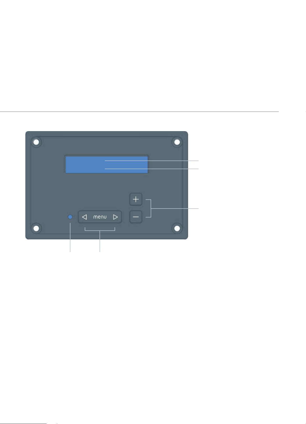
controls and features
Volume
-30dB
power LED menu back/forward
blue - on
red - standby
Use the back/forward arrows to access the
following menus
Volume
Adjusts the subwoofer’s output level.
Low Pass
Adjusts the point at which higher frequencies
are filter ed f rom the subwoofer.
Phase
Allows the phase of the subwoofer to be
0° or 180°.
High Pass Q
Adjusts the character of low frequency
extension of the subwoofer such that the
output at 20Hz remains constant, but the shape
or knee of the roll off above and below this
frequency is altered. The default setting of 0.9
is suitable for most applications. The minimum
setting of 0.5 offers a more gradual roll-off
suited to excessively boomy sounding rooms.
The maximum setting of 1.0 offers more punch
and ouput at 40Hz.
Power Mode
Can be set to auto sense or 12V trigger.
When set to auto sense the subwoofer will
automatically switch on when a signal is
present. The auto sense circuit monitors both
the speaker level or line level inputs. After 15
minutes the subwoofer will switch into standby
if no signal is present.
When set to 12V trigger the subwoofer will
switch on from standby when 12V is applied
to the trigger input on the rear panel of your
subwoofer. This allows the subwoofer to
switch between on and standby in perfect
synchronisation with an AV amp/receiver
equipped with a trigger output.
Auto Sensitivity
Adjusts the subwoofers switch on sensitivity
when a signal is present. When adjusting the
sensitivity the power LED will respond to the
3
menu items
current menu settings
current menu settings up/down
signal level without any time delay. This menu
is only available when power mode is set to
auto sense.
Display Contrast
Allows the display contrast to be adjusted to
suit the lighting conditions and viewing angle.
Restore Defaults
Resets all menu settings to factory default
values. Press and hold + and - buttons
simultaneously to restore defaults,
Menu Lock
Allows control panel to be locked. Press and
hold + and - buttons simultaneously to lock.
Press and hold + and - buttons simultaneously
again to unlock.
Page 4
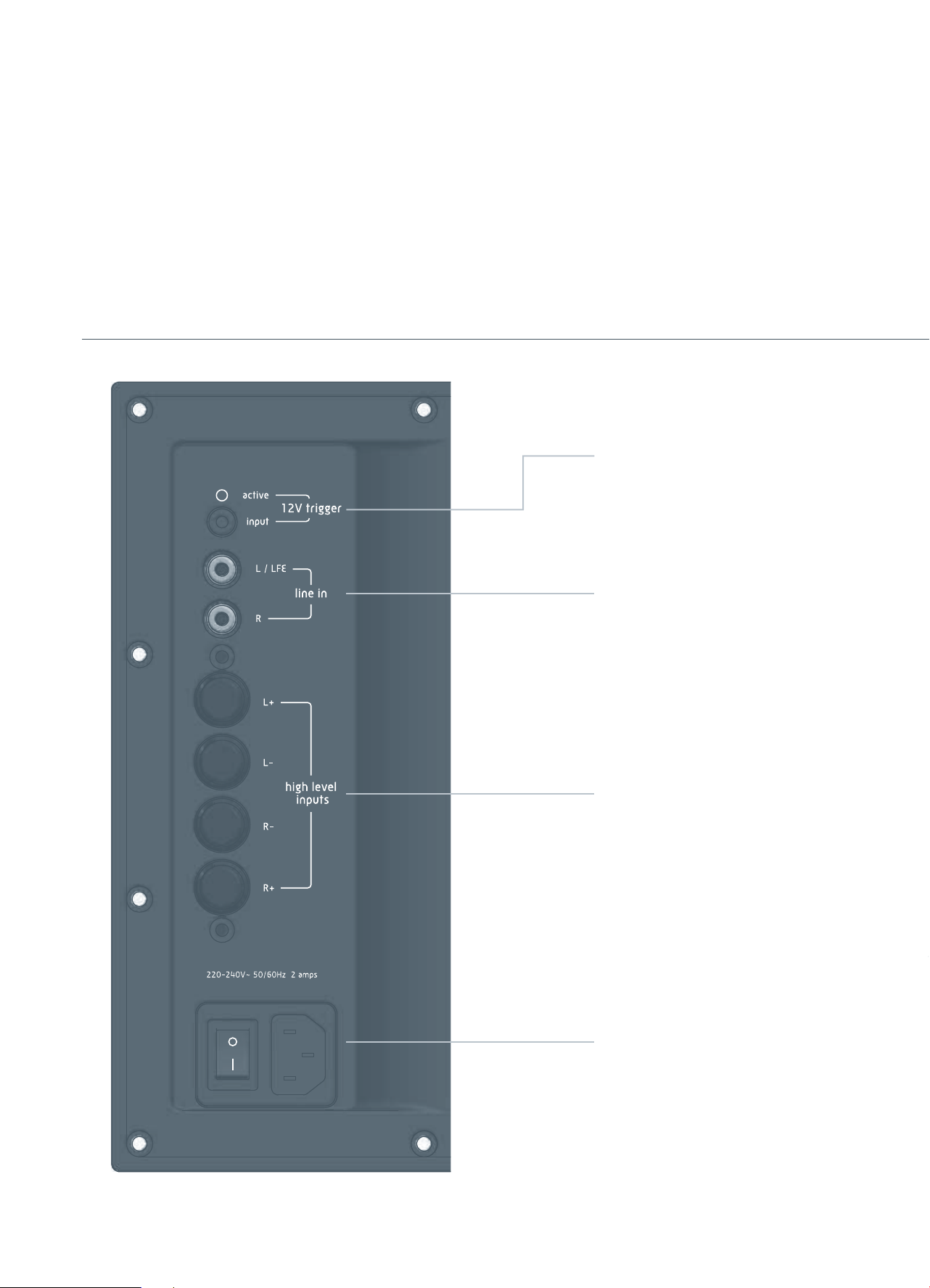
controls and features
12V trigger
When a 12V signal is a applied to the trigger
input the subwoofer will switch on from
standby and the red active LED will illuminate.
Use a 3.5mm mono lead to make the connection
to an AV amp/receiver equipped with a trigger
output. (5-15V DC or AC may be used to trigger
the subwoofer, polarity is not critical).
line in
Line level stereo input with summing function.
high level inputs
High level inputs with summing function, for use
with amplifier speaker outputs.
power switch and socket
Unit should be switched off when not in use for
extended periods.
4
Page 5

Krix Tektonix and Volcanix innovation
controls and features
front panel controls
Unlike conventional subwoofers with hard to
reach rear controls, the Tektonix and Volcanix
feature a front panel with precision digital
adjustment. There is no longer any need to pull
your subwoofer out of a cabinet or away from
a wall to set up your system, all functionality
is accessible via the front panel interface. The
front panel display is backlit to aid viewing in
low light conditions. After 45 seconds of button
inactivity the display will return to the volume
menu and the backlight will fade out.
Volume
-30dB
ICEpower® amplification
Your subwoofer is powered by a low distortion
ICEpower® amplifier designed by Bang &
Olufsen ICEpower a/s. This high efficiency
Class-D amplifier generates far less heat than
conventional amplifiers and therefore requires
no bulky external heatsinking. A high-current
switch-mode power-supply ensures full
power can be delivered for sustained periods,
producing maximum dynamics and impact from
your subwoofer.
In place of conventional mechanical
potentiometers the signal processor
utilises Microchip® laser trimmed digital
potentiometers, this offers precision adjustment
of volume and filter controls, as well as
eliminating noise, distortion and reliability
issues associated with conventional pots.
This all analogue signal path features only high
quality plastic film coupling capacitors and
JFET operational amplifiers for stable low noise
audio performance.
All aspects of the signal processor, including
fault and monitoring signals, are under
the control of a Microchip® PIC16F690
microcontroller, which is commanded from the
front control panel via a high reliability balanced
RS485 serial data link. The front control
panel has its own PIC16F690 microcontroller
dedicated to managing the LCD display and
user interface.
high performance driver
The Tektonix and Volcanix both feature high
power long throw low frequency drivers. Both
units incorporate a 50mm four layer voice coil
and motor system optimised for low distortion
at extreme sound pressure levels.
symmetrix vent
Enclosures feature Symmetrix bass reflex
venting, with the vent exhibiting the same flare
radius internally and externally. This lowers
subwoofer distortion and serves to reduce vent
turbulence or “chuffing” at high drive levels.
clipping protection
The ICEpower® amplifier features sound
optimised soft clipping protection and will
accurately amplify the input signal to full power
without compression or loss of dynamics. If an
input signal is applied beyond the ICEpower®
amplifiers maximum power limit, soft limiting
will minimise distortion and protect the
loudspeaker driver.
fault protection
Subwoofer amplifiers feature comprehensive
protection systems that will protect the
amplifier and loudspeaker from a range of
possible fault conditions.
The microcontroller constantly monitors the
ICEpower® amplifier module for possible overtemperature and over-current events, as well
as checking that the AC mains supply is not too
low for proper operation.
If any of these fault conditions occur, the
amplifier will immediately be disabled to
prevent any permanent damage from occurring.
After the fault condition clears, the unit will
resume normal operation. Please see the
troubleshooting guide on page 10 for further
information.
signal processor
The Tektonix and Volcanix subwoofers feature a
high integrity signal processor through the use
of analogue control stages that form a short
and direct connection from the input terminals
to the ICEpower® amplifier, whilst still allowing
maximum control over the incoming audio
signal.
feet
The Tektonix and Volcanix both feature soft
rubber feet to stop unwanted vibration being
transmitted into the floor.
5
Page 6

The most ‘obvious’ position for your
subwoofer is not always the best
The bass produced by a subwoofer is omnidirectional and very hard for your ears to
localise. Therefore a subwoofer can be placed
virtually anywhere in your listening room
and provide the impression that the bass is
radiating from your main speakers. The quality
of bass however is affected by position of your
subwoofer due to complex acoustic interactions
with your listening room. Depth, punch, and
integration with your main speakers are all
affected by the position of your subwoofer.
Experimentation is always recommended to
achieve the most satisfying results.
A. Often the best place for a subwoofer is in a
corner at the front of your room. This position
generally provides the maximum output from
your subwoofer. If your subwoofer sounds
excessively ‘boomy’ in this location try moving
it out 20-50cm from the corner or along one of
the adjacent walls.
B. Placing your subwoofer along the front wall
of your room, within a metre of a front speaker,
is also a good option. In some setups this will
provide a smoother tonal balance than corner
placement. This position is particularly good
for smaller satellite/bookshelf speakers to help
integrate the sound of the subwoofer and main
speakers.
positioning
C. Some people prefer to hide their subwoofer
next to or behind a couch. Listeners on the
couch may enjoy the extra vibrations felt
through the couch, however the bass produced
from your subwoofer may be easier to localise.
Therefore it may be harder to integrate the
sound of your subwoofer with your main
speakers.
D. Placing your subwoofer away from your
walls can result in satisfying results but
maximum output from your subwoofer may be
reduced.
E. Subwoofers may also be placed inside
cabinetry. Please refer to the link on the
subwoofer page of the Krix website for
suggestions.
!
The subwoofer is not magnetically
shielded; do not place near CRT screens
(old style TVs), and magnetic media.
Avoid placing your subwoofer near sources
!
of heat, direct sunlight, humidity etc.
The rear amplifier panel can get hot,
!
ensure adequate ventilation. Read the
safety instructions on the back of this
manual for more details.
Tip
Many modern receivers include
automatic room correction features. It
is recommended that these correction
features are disabled until an optimal
subwoofer position has been determined.
Tip
To get the most from your subwoofer
we recommend experimenting with the
following positioning technique:
Place the subwoofer in your central
listening position. (You may need to
purchase a long subwoofer input cable)
Disconnect all speakers other than the
subwoofer.
Play some music or a movie with heavy
bass content.
Move around your room, listening at floor
level. Note any changes in the tonal quality
of the bass.
Mark out one or more potential locations
that offer a smooth, extended sound or
a sound quality you enjoy. Relocate your
subwoofer to this location, reconnect
speakers, and listen again from your
central listening positioning. Permanently
locate your subwoofer to this new location
if you notice an improvement in the sound
quality from your subwoofer.
A
D
B
E
C
6
Page 7

connection & calibration - AV receiver
connection and defaults
It is recommended that you use Line
Level RCA connections for home theatre
applications.
Ensure the mains power switch is off and •
connect the mains power cord.
Connect the subwoofer pre-out (SW) •
on your receiver/processor to the line
in L/LFE input on your subwoofer (see
advanced connection methods p.9 for
alternatives).
Switch on mains power switch •
(rear panel).
Check • volume on your subwoofer is set to
the default level, -20dB.
Set subwoofer• low pass to (maximum)
LFE bypass setting. The AV receiver
will manage the crossover/low pass
frequency.
Set • phase to 0°.
Set • power mode to auto (default).
At this time you may wish to perform •
the AV receiver’s automatic calibration
procedure. Alternatively refer to the
manual setup procedure below.
manual receiver setup
Ensure subwoofer is set to ON or YES in your
receiver setup (Refer to your receiver/processor
manual for more information).
Use default subwoofer channel level setting on
your receiver.
On your receiver select desired crossover
frequency/low pass setting. As a guide use the
80Hz setting.
Tip
If your speakers are small (bass driver is
smaller than 5 1/4”) use a higher setting
(100Hz,120Hz,150Hz) to send more of
the bass information to your subwoofer.
Consult your receiver manual for further
bass management options and settings.
manual subwoofer calibration
When using the subwoofer in a home theatre
installation it is beneficial to listen to movies
with extended periods of low bass (explosions,
Volume
-20dB
rumbles etc). This will allow you to evaluate
the ‘impact’ and ‘depth’ of your subwoofer. It
is also beneficial to select music that is familiar
to you when carrying out listening tests. As a
suggestion play clean unprocessed recordings
that use double bass, bass guitar, cellos, organ
or kick drum etc. that cover a wide bass
spectrum.
Begin by playing the movie/music and slowly
adjust the volume setting on the subwoofer to
your desired level.
Tip
For final tweaking of your subwoofer
level you may wish to sit in the primary
listening position and adjust the
subwoofer channel level using your
receiver’s remote control. (Refer to your
receiver’s manual for more information)
Now set the phase setting. The correct phase
setting will produce the most bass. You may
7
to AV receiver
need to listen to a variety of recordings to hear
any subtle change in bass energy. If no change
in bass energy can be heard between phase
settings, set phase to 0° default setting.
Re-adjust volume if necessary.
Page 8

connection & calibration - stereo system
connection and defaults
Connect the Tektonix or Volcanix subwoofer
to a stereo amplifier either via the high
level speaker inputs or the line level inputs.
Ensure the mains power switch is off and •
connect the mains power cord.
Connect subwoofer to your stereo amplifier •
using one of the methods on this page.
Using both connection methods
!
simultaneously is not recommended.
Connection Method 1: Line Level
Requires your amplifier to feature L&R pre-
!
out connections.
Use two Y cables to connect each Pre-out •
channel on your amplifier (or preamplifier) to the corresponding subwoofer
and main amplifier inputs. If main inputs
are not present on your amplifier simply
connect the pre-outputs to subwoofer line
inputs.
L
R
Pre-out Main-in
Stereo Amplifier
Connection Method 2: High Level Inputs
Not suitable for use with bridge-mode
!
amplifiers.
Connect the Speaker Level outputs on your
main amplifier to the Speaker Level inputs on
the rear panel of the subwoofer.
to left speaker to right speaker
Stereo Amplifier
speaker A output
--
--
speaker B output
Also connect the Speaker Level outputs on
your main amplifier to each of your left and
right speakers. The subwoofer ‘senses’ the
speaker level signal. No additional load will be
placed on your amplifier. Be sure to maintain
correct phasing for each set of speaker leads,
red (positive +) to (+) and black (negative -)
to (-).
Where your amplifier has A & B speaker
Tip
outputs you may wish to connect your main
speakers to A and subwoofer to B. Use
amplifier A+B setting to activate subwoofer
and A only setting to mute subwoofer.
33
33
8
calibration
Switch on mains power switch (on the •
rear panel).
Check the • volume on your subwoofer is set
to the default level, -20dB .
Select desired • low pass (crossover
frequency) setting on your subwoofer. As a
guide set the subwoofer low pass to 20Hz
above the main speakers low frequency
limit. (Refer to main speaker specifications
e.g. 60Hz-20kHz speaker would require
80Hz setting)
Set • phase to 0°.
Set • power mode to auto (middle position).
It is beneficial to select music that is familiar
to you when carrying out listening tests and
calibration procedures. As a suggestion play
clean unprocessed recordings that use double
bass, bass guitar, cellos, organ or kick drum etc
that cover a wide bass spectrum.
Begin by playing music and slowly adjust
the volume setting on the subwoofer to
your desired level. For final tweaking of
your subwoofer level you may wish to sit
in the primary listening position and ask an
assistant to adjust the volume setting on your
subwoofer.
Now set the phase switch. The correct phase
setting will produce the most bass. You may
need to listen to a variety of recordings to hear
any subtle change in bass energy. If no change
in bass energy can be heard between phase
settings, set phase to 0° default position.
Re-adjust volume if necessary.
You may wish to fine-tune the crossover
frequency/low pass setting. This will vary
the amount of overlap from the subwoofer to
the main speakers and increase or decrease
the level at those frequencies. The effect is a
strengthening or weakening of the upper bass
region. Unpleasant ‘woody’ or ‘chesty’ sound
qualities may suggest the low pass setting
selected is too high. If the sound lacks ‘body’
the low pass setting selected may be too low.
Re-adjust low pass setting, volume and then
phase. Re-evaluate results.
Page 9

advanced connection methods
one subwoofer - stereo connection
If your receiver has a stereo L & R subwoofer
output feature, connect both L & R outputs to
your subwoofers L & R line inputs.
Main AV Receiver
From L & R sub-outs
Tektonix or Volcanix
two (or more) subwoofers - mono connection
Using multiple subwoofers can be useful in
large or troublesome installations where more
uniform bass coverage is desired. If your
receiver has only one subwoofer output, use a
RCA Y-connector to connect both subwoofer
L/LFE inputs to the one mono SUB output.
Main AV Receiver
From sub-out(mono)
subwoofer one subwoofer two
left and right subwoofers - stereo connection
If your receiver has stereo line level subwoofer
outputs a left and right subwoofer may be used
to allow stereo low bass reproduction.
Connect each receiver sub output to the
corresponding subwoofer:
L sub out to the left subwoofer L/LFE input
R sub out to right subwoofer L/LFE input
Main AV Receiver
From L & R sub-outs
left subwoofer right subwoofer
9
Page 10

trouble shooting
symptom
Power LED - double flashing red
Power LED - flashing red
Power LED - flashing blue
No sound from subwoofer
(Power LED is red)
Minimal deep bass produced
(Power LED is blue)
Subwoofer will not switch into standby.
(Power LED is always blue)
cause
Low mains voltages or brown-out in your area.
Amplifier over-temperature condition. May be
the result of continual use of the subwoofer at
high volume levels.
Amplifier overcurrent condition.
Incorrect or faulty cabling.
AV amp/receiver subwoofer output settings
incorrectly set.
AV amp/receiver sending bass to main speakers
(may differ for music and movies)
Program material has little bass content
Subwoofer influenced by room placement
If power mode is set to auto sense, noise
in your system may be triggering the auto
sense circuit causing your subwoofer to stay
switched on.
If power mode is set to 12V trigger and trigger
cable is connected to AV amp/receiver the
trigger logic may be incorrectly set.
treatment
Contact your power provider.
Subwoofer will resume normal operation when
unit cools. If problem persists contact your Krix
retailer or Krix directly.
Switch off and switch on unit to reset. If
problem persists contact your Krix dealer or
Krix directly.
Check interconnection cables.
Refer to AV amp/receiver for subwoofer setup
procedure.
Refer to AV amp/receiver for subwoofer setup
(may differ for music and movies)
Play different source material.
Reposition subwoofer, refer to page 6.
Reduce auto sensitivity menu setting until
unit switches off when no program material is
playing.
Refer to AV amp/receiver for trigger setup
procedure.
Subwoofer will not turn on or will go into
standby when very quiet source material is
played.
Communication Error (1 or 2) on display
Subwoofer will not turn on
(Power LED not illuminated)
If power mode is set to auto sense, the auto
sense circuit may not be responding to your
low level source material.
If power mode is set to 12V trigger and
trigger cable is connected to AV amp/receiver,
subwoofer may not be receiving a 12V signal.
The front control panel is unable to
communicate with the rear panel.
Amplifier not receiving power.
10
Increase auto sensitivity menu setting until
unit switches on when very quiet source
material is played. If problem persists you may
also wish to increase the subwoofer output
level on your A/V receiver. Refer to AV amp/
receiver for subwoofer setup procedure.
Check trigger cable connection and then refer
to AV amp/receiver for trigger setup procedure.
Turn subwoofer mains power off and on. If
problem persists contact your Krix retailer or
Krix directly.
Check power switch is set to ‘I’.
Check mains outlet is suppling power using
another appliance (e.g. lamp).
If problem persists contact your Krix retailer or
Krix directly.
Page 11

specification
warranty
5 year warranty applies to the cabinet and
speaker.
2 year warranty applies to the amplifier and
related internal electronics.
(Refer to the details on the warranty card
supplied)
queries
If you have any queries regarding the Tektonix
or Volcanix setup procedure or any other Krix
product, please contact your nearest Krix
retailer or Krix directly. Contact details are on
the back cover of this booklet.
Tektonix: specifications
Drivers
Bass Driver
Electronics
Amplifier Power
Amplifier S/N
Distortion
Line Level Inputs
General
Frequency Range
Output
Auto Power On / Off
Phase Select
Filters
Cabinet
Enclosure Type
Dimensions
Material
Finish
Weight
- Input to Speaker
Nominal 275mm (11”) diameter paper cone driver, 50mm long throw
voice coil, developed for high level, low frequency reinforcement
450 watts RMS into the nominal 4 ohm driver
>90dB
<0.1% - @ 400 watts RMS
Left Input (mono) 300mV RMS for maximum output
Left + Right Input (stereo) 150mV RMS for maximum output
22Hz - 200Hz (-6dB) in room response
123dB maximum SPL in room response
15 minute delay before switching to standby after no input signal
0° or 180° (relative to input signal)
Low pass filter 50-195Hz, Bypass
High pass filter to limit driver excursion below 26Hz
Bass reflex, front vented
451mm high x 360mm wide x 415mm deep (including grille and feet)
18mm MDF
Vinyl or lacquered timber veneer
18kg
Volcanix: specifications
Drivers
Bass Driver
Electronics
Amplifier Power
Amplifier S/N
Distortion
Line Level Inputs
General
Frequency Range
Output
Auto Power On / Off
Phase Select
Filters
Cabinet
Enclosure Type
Dimensions
Material
Finish
Weight
Due to continued development specifications may change without notice.
- Input to Speaker
Nominal 305mm (12”) diameter paper cone driver, 50mm long throw
voice coil, developed for high level, low frequency reinforcement
450 watts RMS into the nominal 4 ohm driver
>90dB
<0.1% - @ 400 watts RMS
Left Input (mono) 300mV RMS for maximum output
Left + Right Input (stereo) 150mV RMS for maximum output
16Hz - 200Hz (-6dB) in room response
125dB maximum SPL in room response
15 minute delay before switching to standby after no input signal
0° or 180° (relative to input signal)
Low pass filter 50-195Hz, Bypass
High pass filter to limit driver excursion below 22Hz
Bass reflex, front vented
506mm high x 400mm wide x 470mm deep (including grille and feet)
18mm MDF
Vinyl or lacquered timber veneer
23kg
11
Page 12

Krix Loudspeakers Pty Ltd
14 Chapman Road
Hackham SA 5163
Australia
T 61 8 8384 3433
F 61 8 8384 3419
listen@krix.com Rev #10001
krix.com
Please read these important safety instructions before you plug in this equipment.
Please retain these instructions for future reference.
This equipment is manufactured to a very high standard and it should give you many years of reliable service. To minimise the chance of
any problems with this equipment, take note of the following:
This equipment uses electricity at very high voltages. To avoid injury to persons, fire or damage to the unit:
• Do not use the unit near water (or something with water in it) or in the rain.
• Do not allow the unit to get wet.
• Clean the unit with a dry cloth only – do not use solvents. Unplug the unit before cleaning.
• Do not plug the unit into a power source other than the one specified.
• Make sure the power cable is protected.
• Make sure the power cable is not being pinched and that it cannot be walked on.
• Never disconnect the ground prong on the mains plug.
• When removing the power plug from the power source, do not pull on the cord.
• Do not open the unit. Refer any service to qualified service personnel.
• Do not place any thing or any part of your body into the unit.
This unit may get hot when it is being used. To avoid injury to persons, fire or damage to the unit:
• Do not put the unit near any heating source.
• Keep the unit out of direct sunlight.
• Make sure all ventilation openings are clear.
• Do not cover unit with blankets or any other materials.
• Do not place unit against curtains or furnishings.
This equipment is heavy. To avoid injury to persons:
• Be careful when you lift the unit.
• Install the unit on the ground so that it cannot fall onto anyone.
This equipment can cause extreme vibrations. To avoid injury to persons, fire or damage to the unit:
• Do not put the unit near things that might be damaged by vibration.
• Do not put the unit near things that might be moved by vibration (for example vases, candles or glass objects).
• Do not put objects on top of the unit.
This equipment is delicate. To avoid damage to the unit:
• If it starts to make a distorted or unusual noise, turn the volume down. If that makes no difference, turn the unit off and have it
checked by qualified service personnel.
• If you are not going to use the unit for an extended period, unplug it from the wall socket.
• If there is a storm with lightning, unplug it from the wall socket.
• Never force any switches or controls. If they are difficult to operate, have the unit checked by qualified service personnel.
• Do not put any objects on the unit.
Avoid damage to your hearing. You only have one set of ears!
All sound equipment is capable of damaging your hearing or the hearing of others. Exposing your hearing to high volume levels for
extended periods of time will cause permanent hearing damage. Even short periods at extremely high levels will cause permanent hearing
damage. Children’s hearing is especially sensitive and extra care should be taken when exposing children to high volume levels. Hearing
damage is cumulative and it may be too late when you find out that your hearing has been damaged. We recommend that you avoid long
periods of exposure at excessive volume levels.
 Loading...