

Krill Avanti S jet 2.1m ARF Assembly Manual

The all new sport/3d jet is a masterpiece!! Designed by Italy’s Sebastiano Silvestri. Its
design is based on a hawk aircraft. And then been improved further with aerodynamic
ideas learned on other pattern models.it is a very lightweight and strong construction.
This helps, as the flight speed rang is really impressive!! Designed to take an engine with
100n of thrust, it is setup to be an ideal jet trainer BUT with a 220-250n turbine you have
the ultimate 3d jet!!
This will let you into a totally different flying experience!!
Krill Avanti S jet 2.1m ARF
Assembly manual.
Specification: setup range of i ns t all ation:
Wingspan:…2.1m Turbine:…..from 100n to 250n
Length:….2.22m radio:…..9-12 channel radio system
Weight: RTF dry (p100)…10.5kg servos:8 digital, metal gear servos.
1.

Required Radio, batteries and turbine
Radio equipment:
• Digital servo:5 JR ds8411 (ailerons, elevators, nose steering
3 JR ds8911 (flaps and rudder)
(2 JR ds 8915(vectoring thrust-optional)
• For pneumatic landing gear operation: one dual air valve (not included)
• For pneumatic brake operation :one single air valve(not included)
• Powerbox systems range from:
Sports setup: powerbox champion or powerbox royal.
3d setup: powerbox roy al or powerbox cockpit + igyro
• We recommend using a powerbox smoke pump
• RX Batteries can be from 2500-3500mah-2s lipo
Recommended turbines:
• For Jet beginners:p100
• For FAI F3S aerobatics:140n to 160n
• For 3d unlimited flight:180n-250n (vectored thrust pipe optional)
Recommended tank:
• Sebart tank for kero +UAT+Smoke (optional with kit)
• 3d setup users with 180n or more. The fuel systems must have a high flow system. The
recommended tank will not produce the amount of fuel these big engines are required .There for
the standard tank design is not recommended.
BISHOP AVIATION: CMJETS 5.6l fuel tank only. Used with a high flow composite fuel trap.
2.
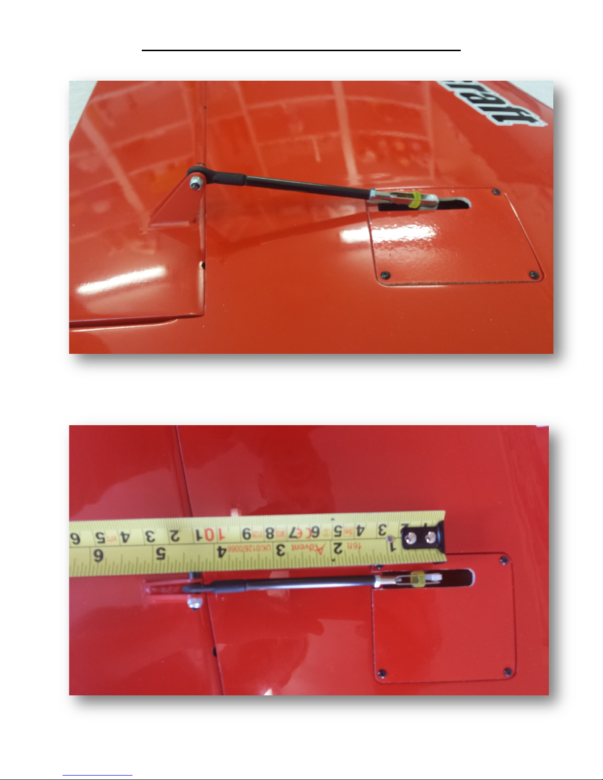
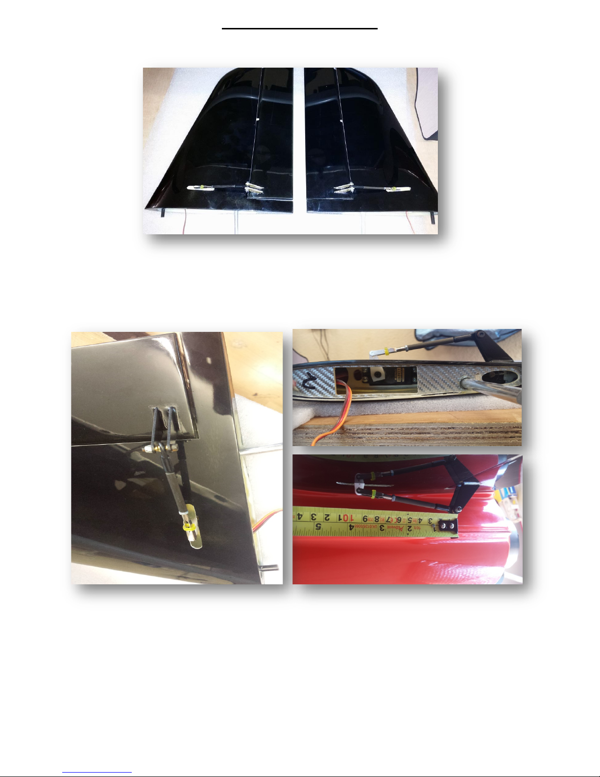
Wing Assembly (Aileron servo JR ds8411.)
Aileron rod length and horn position (note Aileron horn is 5mm back from wing skin, set
with zero aileron deflection).
Aileron linkage length is 110mm from ball to servo horn.
3.
Wing Assembly (Flap servo JR ds8411. horn and rod position)
(Note Flap horn is 10mm from flap hinge line).
Flap rod length is 80mm long from ball to servo horn.
4.
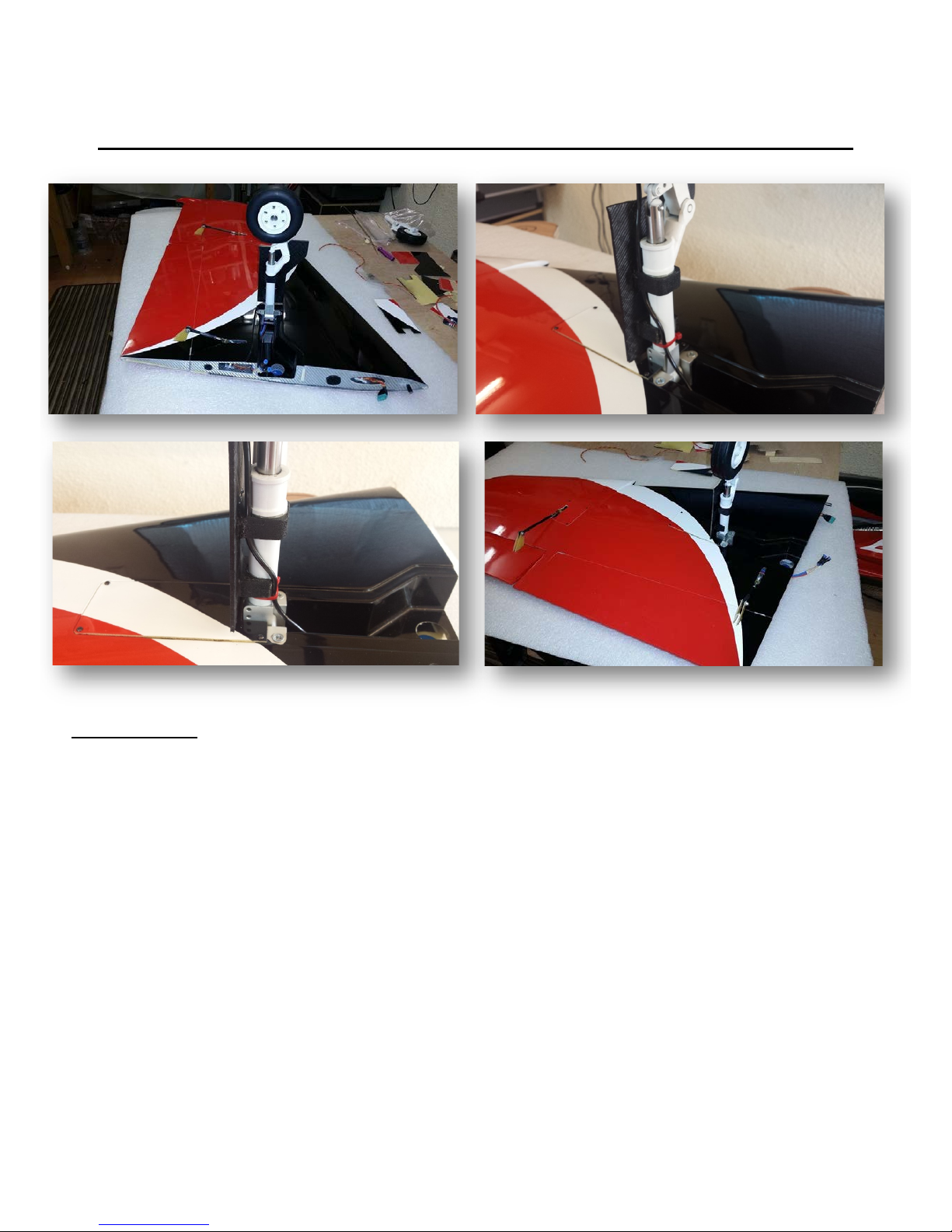
Wing Assembly (door/leg and front dowel modification )
Door assembly
After fitting the retract into the pre-moulded cut outs in the wing. Make sure the leg retracts with room to spar and
is not touching wheel well skin. Now it is time to slide the top door fixing though the leg when it is removed. Refit leg to the
retract and align the wheel parallel to the wing root face. Retract the leg and make sure it is completely locked. Now slide
the half round second door fixing 10mm out from the leg base.(sand if necessary).now place door over the moulded slot
and make sure that there is a 1mm gap round the outside of the door to allow for movement in flight.(note door shape has
to be significantly shaved down to clear leg upon suspension). After you are satisfied that the door sits flush with wing
skin, you can now epoxy the door to the fixings. After cleaning and etching place epoxy on the top faces of the two
mounting blocks and place door in the correct position. Apply tape if necessary to hold in place.
After glue is dry remover leg from retract and care fly slide door out of the leg. Apply more epoxy if required.at this
stage you can paint the door if want to. Now etch all remaining surfaces that is left to be glued and then apply to the leg
and inside of the door fixings. Slide door assembly into the leg and reassemble leg to the retract. Making sure leg is fully
retracted and locked. Hold firmly until epoxy is dry. Repeat these stages on wing number 2.
5.
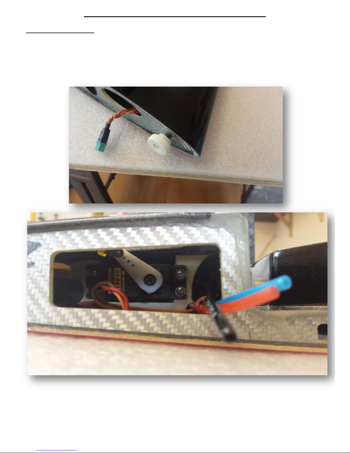
Wing assembly (wires and air tubing)
Front dowel modification
After fitting and fixing the wing half’s to the Fuselage. You may find there is some rear movement when
wing is Pulled back. This can cause the flap to touch the fuselage wing face.Replacing a 6mm thread to the front
dowel which is held in place with a thumb screw, will make sure that in flight.The wing will not move and lock the
flap up in flight.
Wires and air tubes can be rooted through the small tube that is installed at the front of the flap servo mounts.
The flap wire is rooted through this tube and across the retract bay and then though to the front of the wing
root.
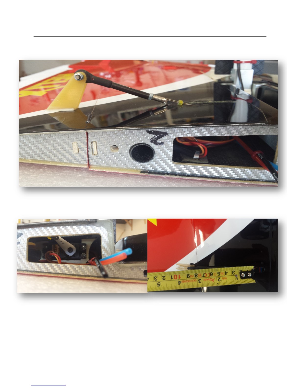
6.
Tail stab Assembly
Install the JR ds8411 into the stab half with the servo horn set with horn facing to the front of the tail half. Make
sure you thread servo wire through the small hole before slotting in the servo.
Length of the push rod in 94mm from ball to servo horn.
Elevator horns are set 5mm back from the tail skin. This will make the hinge line and horn pivot in line at zero
deflection.
7.
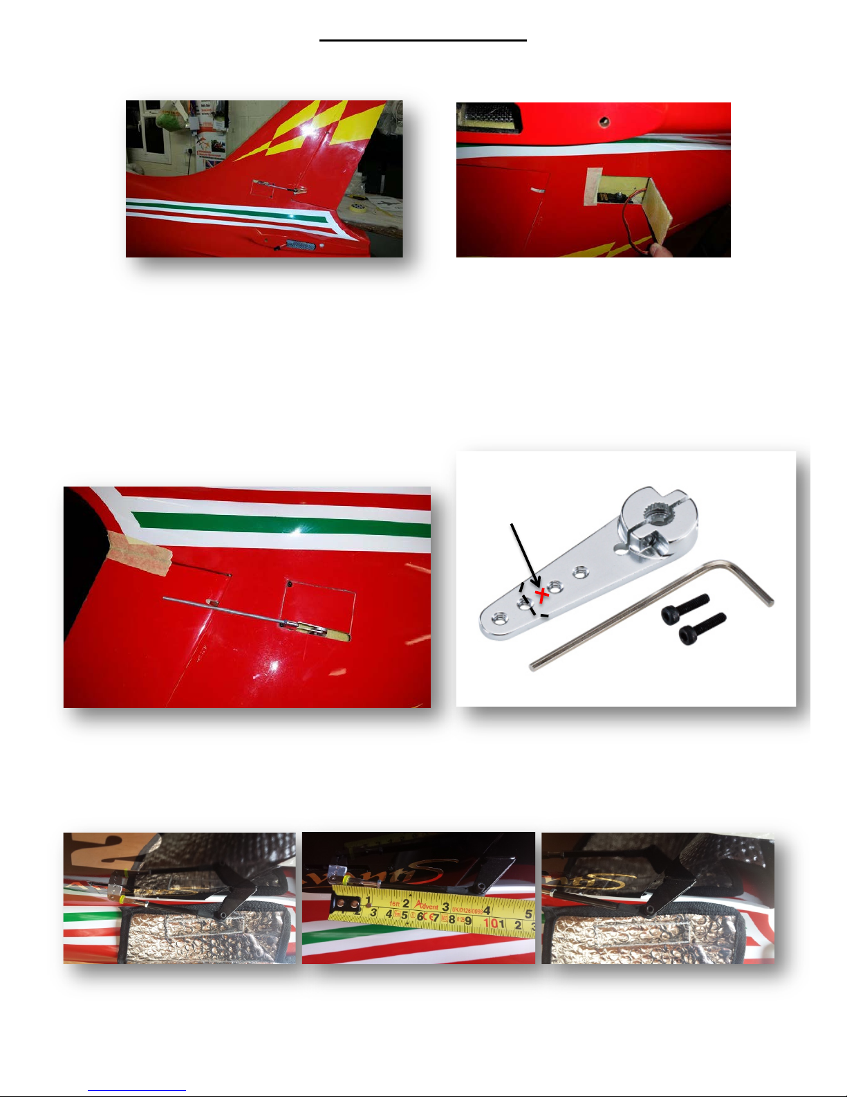
Rudder Assembly
Rudder hinges are factory finished and require no attention but it is good practice to check glue joints and
movement.
First install the JR ds8511/8911 into the pre-cut hatch on the side of the fin. Servo mount is located on the top of
the hatch and will be easier to install with the plane inverted. Make sure the servo wire in pushed thought the
small pre-cut hole in the servo mount. Fit a metal JR 3d horn onto the servo and cut out a slot which is 90% of
the hatch length. Centre servo then drill a 1.5mm hole in the middle of the second and third hole to take a clevis.
And trim remaining horn off. As Seen below.
Rod length is 92mm from ball to servo hole.
Rudder double horn is positioned 5mm back from fin skin with zero deflection on rudder. Cut rudder horns
parallel to the servo movement to inshore there is no fouling.
8.
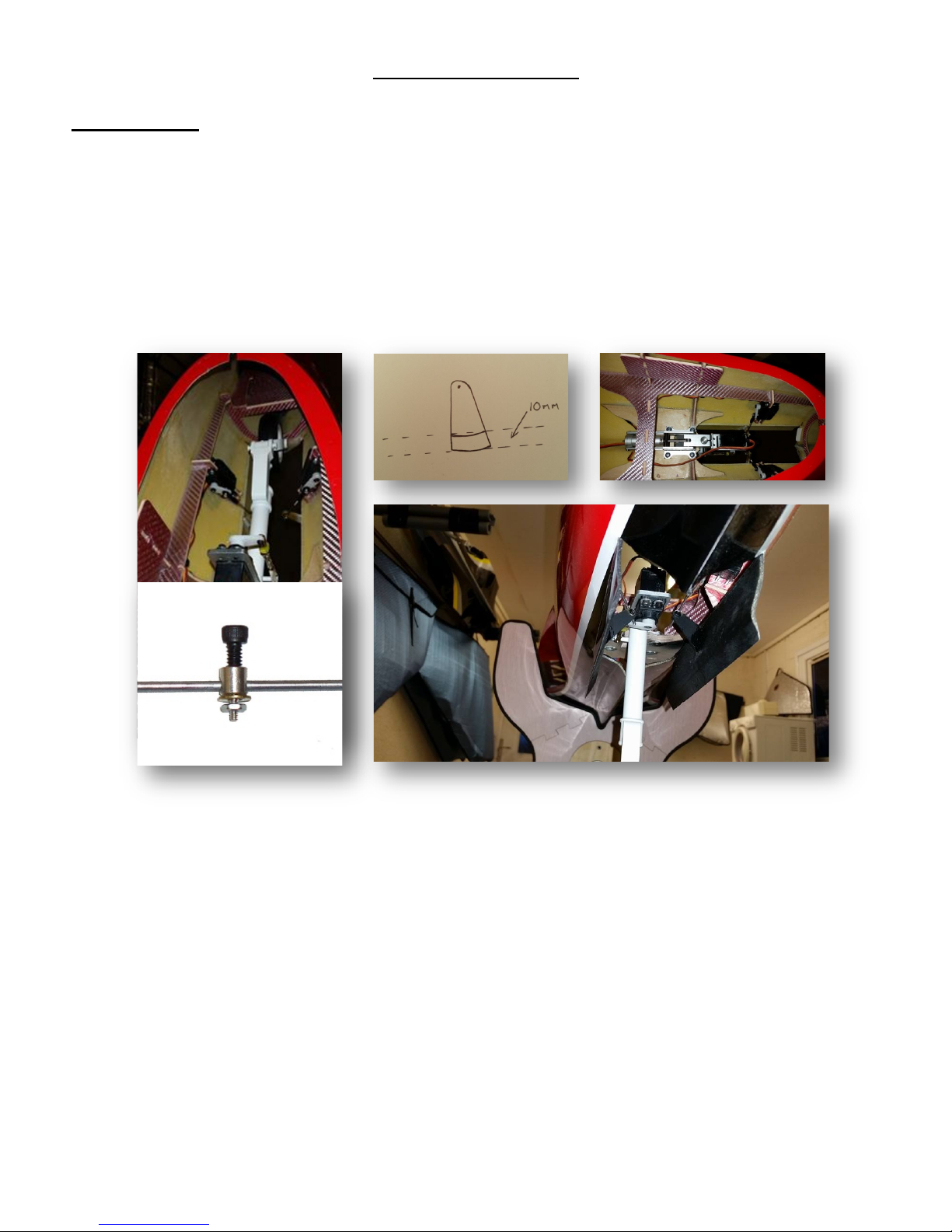
Fuselage Assembly
Front doors
The front doors are ready hinged from the factory and just require a horn and servo
install to complete.
First select the two horns provided in the bag of horns. They require 10mm
reduction to clear the nose leg upon retraction.
Install the midi servos as shown in the picture above. Now setup a 2mm threaded rod and ball
link system to the servo horn. Also fit a 2mm clamp fitting to the door horns. This setup makes
travel adjustment easier later. Slide 2mm rod through the door horns and tighten clamp with the
servo horn down at a 45 degree angle and also door fully open. Door horn should be 5mm away
from hinge line of the doors. After making sure the rod and horns are perfectly in line you can
tack with C.A and then manually check operation. When you are happy, you can epoxy horn
joints for a permanent fixing.
Installing the nose leg retract is easy. Just make sure that the retract sits completely on the
plywood plate, without it distorting the retract unit.
(Note after completing the front door. Make sure the doors close without too much strain to
the servos. Sand if necessary).
9.
 Loading...