

© Krick Modelltechnik, Germany, Stand 27.11.2017
Die Abbildung zeigt das Modell mit Brushless-Antrieb
Sea Jet Evolution
Montage- und Bedienungsanweisung
Bestell-Nr. ro1266

2 © Krick Modelltechnik, Germany, Stand 27.11.2017
Bau- und Bedienungsanleitung
Sea-Jet Evolution
Nr.
ro1266
Technische Daten:
Länge: --------------------------------------------- ca. 685 mm
Breite: ---------------------------------------------- ca. 240 mm
Höhe: ------------------------------------------------ca. 370 mm
Verdrängung: -------------------------------------- ca. 2100 g
Nicht enthaltenes, jedoch erforderliches Zubehör sowie Klebstoff e siehe Beilageblatt.
Werkzeuge und Hilfsmittel siehe Krick-Hauptkatalog
Allgemeine Hinweise für den Bauablauf und
zur Bauanleitung
Die Nummerierung entspricht im Wesentlichen der Reihenfolge
des Bauablaufs.
Verschaff en Sie sich bitte in Verbindung mit den Kurztexten der
Anleitung, der Stückliste und den Abbildungen einen Überblick
über die jeweiligen Bauschritte.
In der Anleitung fi nden Sie auch eine Übersichtszeichnung für
die Laserteile und einen Schaltplan.
Lötstellen an Steck- bzw. Kabelverbindungen mit Schrumpfschlauch isolieren.
Richtungsangaben, wie z. B. links und rechts sind in Fahrtrichtung zu sehen.
Alle Maße im Text oder in den Abbildungen sind in mm angegeben.
Tiefziehteile
Nach Beschneiden der Tiefziehteile Schnittkanten mit Schleifpapier glätten.
Die Bohrungen in den Tiefziehteilen nach Markierungen und
Maßangaben in den Abbildungen anbringen.
Laser-Cut Teile
Nur die Teile austrennen, die in der entsprechenden Baustufe
benötigt werden.
Das Auffi nden der Teile erleichtern die Identifi kations-Zeichnungen. Die Teile entsprechend nummerieren.
Beim Austrennen der Laser-Cut Teile die Stege und Grate mit
einem scharfen Balsamesser bzw. einer Dreikant-Schlüsselfeile entfernen. Die Laser-Cut Teile müssen locker ineinanderpassen, ohne zu klemmen.
Klebearbeiten
Alle Klebestellen vor dem Auftragen des Klebstoff s mit Schleifpapier aufrauen.
Nur die von uns empfohlenen Klebstoff e verwenden. Die Verarbeitungsvorschriften der Klebstoff hersteller beachten.
Zum Verkleben von Rumpf und Deck wird Silikonkleber oder
Silikondichtmasse empfohlen. Für diesen Klebevorgang bitte
nur diesen Klebstoff verwenden, damit die Verbindung später
einmal wieder geöff net werden kann.
Bitte beachten: Der Silikonkleber benötigt ca. 24 Stunden zum
Aushärten.
Alle Teile vor dem Verkleben immer erst “trocken” anpassen.
Bei der Verarbeitung von Acrylit-Klebstoff keine dicken Leimraupen aufbringen, sondern den Klebstoff ausstreichen. Alle
Klebestellen am Rumpf, an welchen Wasser eindringen könnte
(Ruderlager, Stevenrohre etc.) mit Acrylit-Klebstoff dicht vermuff en.
Nach dem Auftragen von Klebstoff die Teile mit Klammern bzw.
Klebestreifen in der Position halten. Kleine Mengen Sekundenkleber werden mit einer Nadel oder einem dünnen Draht
aufgebracht.
Hinweise zur Fernsteueranlage
Als Fernsteuerung benötigen Sie eine Anlage ab 2 Kanälen mit
einem Servo sowie zwei elektronischen Fahrtreglern mit BECFunktion bei Brushless-Antrieb oder einem Fahrtregler für zwei
Motoren beim Einbau des Standard-Bürstenantriebs.
Orientieren Sie sich vor Baubeginn über die Einbaumöglichkeit
der zu verwendenden Fernsteuerung.
Sollte eine andere, als die von uns vorgeschlagene Steuerung
verwendet werden, können Sie sich nach dem Einbauschema
richten. Maßdiff erenzen sind von Ihnen selbst auszugleichen.
Beim Verlegen der Litzenantenne des Empfängers bitte die
Anleitung der Fernsteuerung beachten.
Das Servo vor dem Einbau mit der Fernsteuerung in Neutralstellung bringen (Knüppel und Trimmhebel am Sender in Mittelstellung). Eventuell montierte Steuerscheibe oder Servohebel
entfernen.
Zur Inbetriebnahme immer den Gasknüppel in Stellung „Motor
aus“ bringen, den Sender einschalten. Erst dann den Akku
anschließen.
Zum Ausschalten immer die Verbindung Akku – Motorregler
trennen, erst dann den Sender ausschalten.
Hinweise zur Lackierung
Eine Lackierung des Bootskörpers ist nicht erforderlich.
Hinweis zur Stückliste
n.e. = nicht enthalten
MS = Messing
Ku = Kunststoff
Ku Sp = Kunststoff -Spritzteil
Tzt = Tiefziehteil
La = Laser-Cut Teil
AS = im Antriebssatz enthalten, nicht im Baukasten
© Krick Modelltechnik, Germany, Stand 27.11.2017 3
Nr.
ro1266
Bau- und Bedienungsanleitung
Sea-Jet Evolution
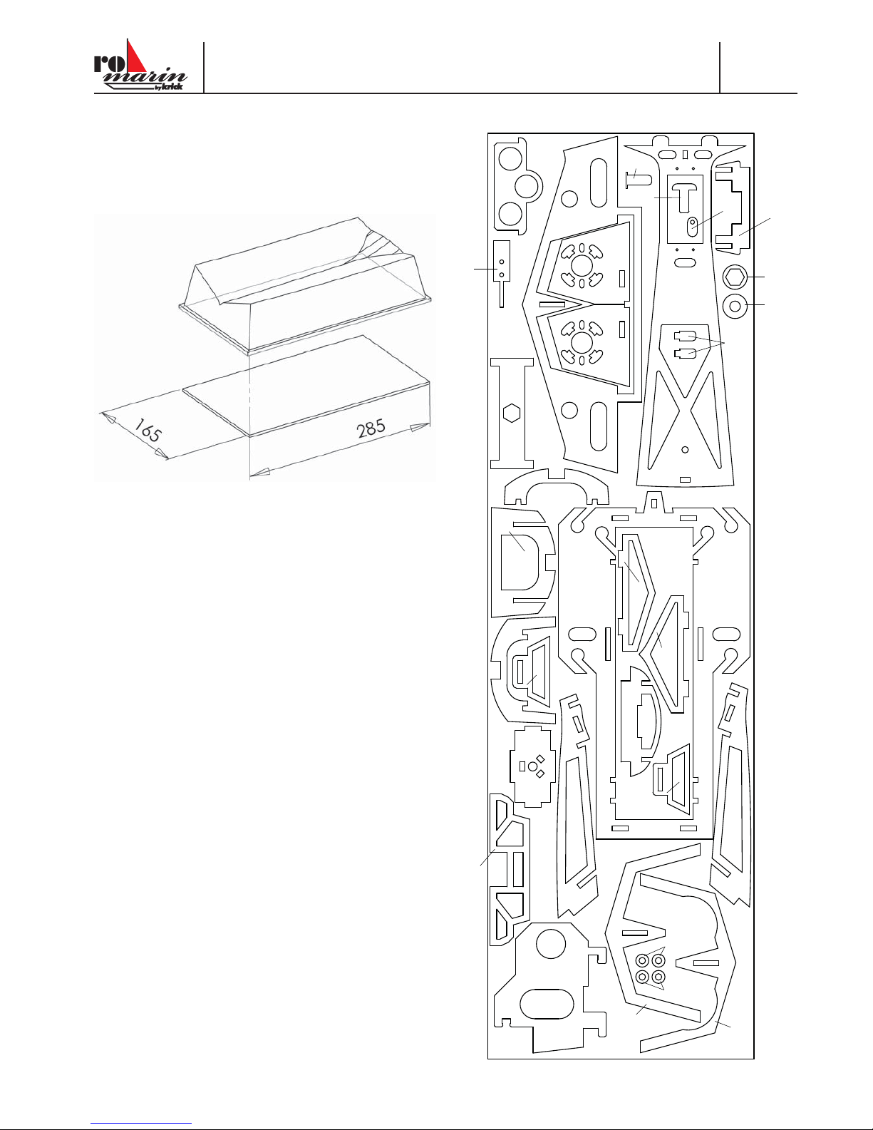
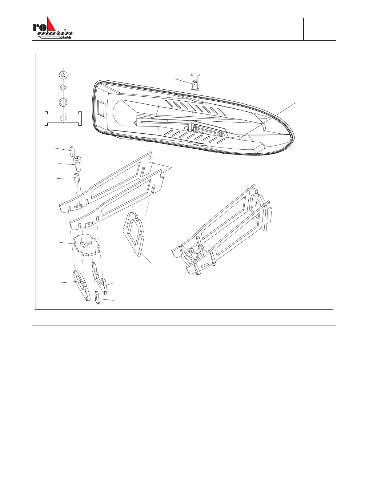
Bootsständer
Der Bootsständer liegt als fertiges Tiefziehteil bei. Zur Versteifung kann eine 4 mm dicke Sperrholzplatte (nicht enthalten)
eingeklebt werden.
Laserplatte Sea- Jet Evolution
1.12
1.3
1.2
1.1
1.4
1.4
1.13
1.14
1.15
1.16
1.17
1.18
1.19
1.18
3.8a
3.9
3.10
4.6
3.17
3.11
3.15
3.14
3.16
4.3
3.13
3.13
3.7
3.12
3.4
3.3
5.1b
5.1b
4 © Krick Modelltechnik, Germany, Stand 27.11.2017
Bau- und Bedienungsanleitung
Sea-Jet Evolution
Nr.
ro1266
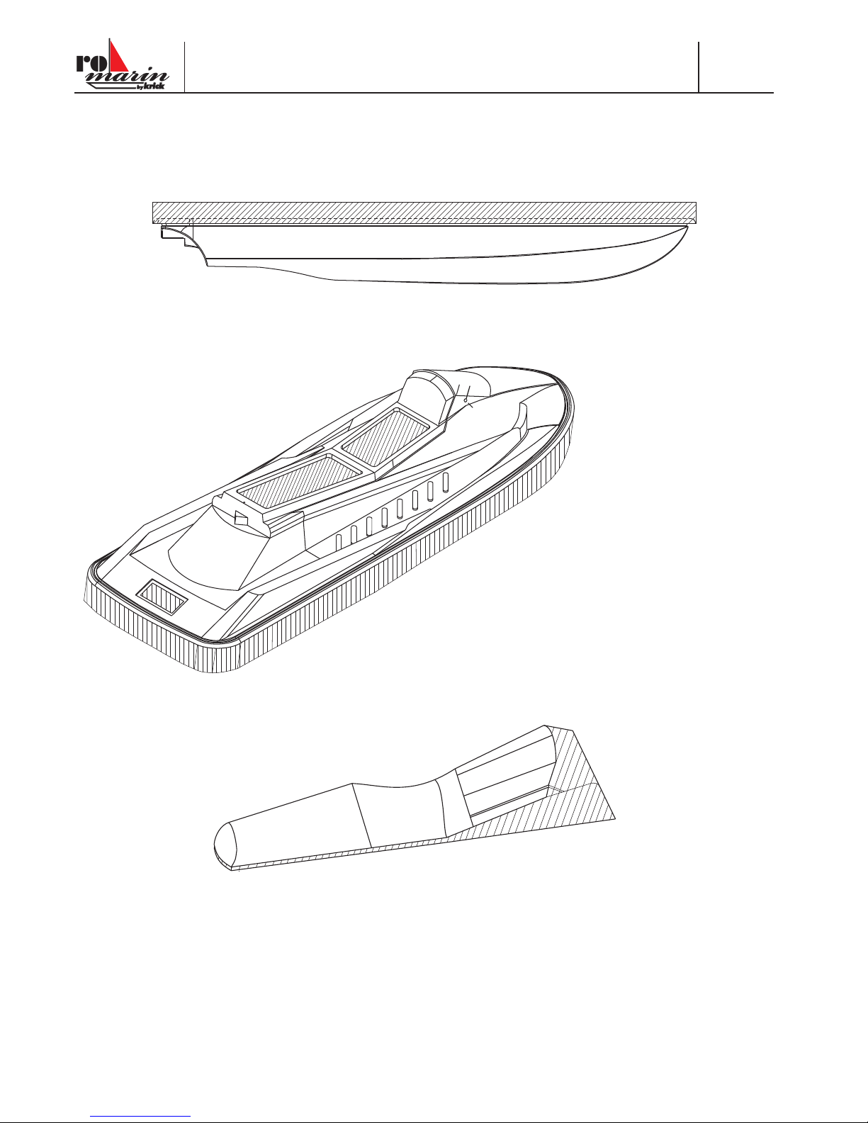
Baustufe 0 Vorbereitung der Teile
Schneiden Sie die schraffi ert markierten Ränder an den Vakuum-Tiefziehteilen ab. Nehmen Sie hierzu nächst die Rumpfunterschale und ritzen Sie mit einem Modellbaumesser in der äußersten Innenkante mehrmals an, bis Sie das überstehende Material
nach außen umknicken können. Nach mehrmaligem hin- und herbiegen knickt das Material an der gewünschten Kante ab.
Beim Rumpf-Oberteil gehen Sie in gleicher Weise vor, wie zuvor beim Rumpfunterteil. Hier müssen Sie allerdings etwas mehr
Vorsicht walten lassen, da die Kante zum Einritzen leicht in den Radius übergeht, der die Klebeverbindung mit der Unterschale
darstellt. In diese gewölbte Kante sollte möglichst nicht eingeritzt werden. Ritzen Sie wirklich nur entlang der äußersten Kante
und knicken Sie den Rand wie zuvor ab.
Weiterhin müssen die beiden
Öff nungen im Bereich des Sitzes
ausgeschnitten werden. Hier
ritzen Sie von oben in der unteren
Kante der Öff nung rundherum mehrmals ein, bis das Teil
von selbst herausfällt. Dieses
Restmaterial bitte noch nicht
wegwerfen. Es wird hiervon noch
ein Reststück für den hinteren
Lukendeckel 3.2 benötigt.
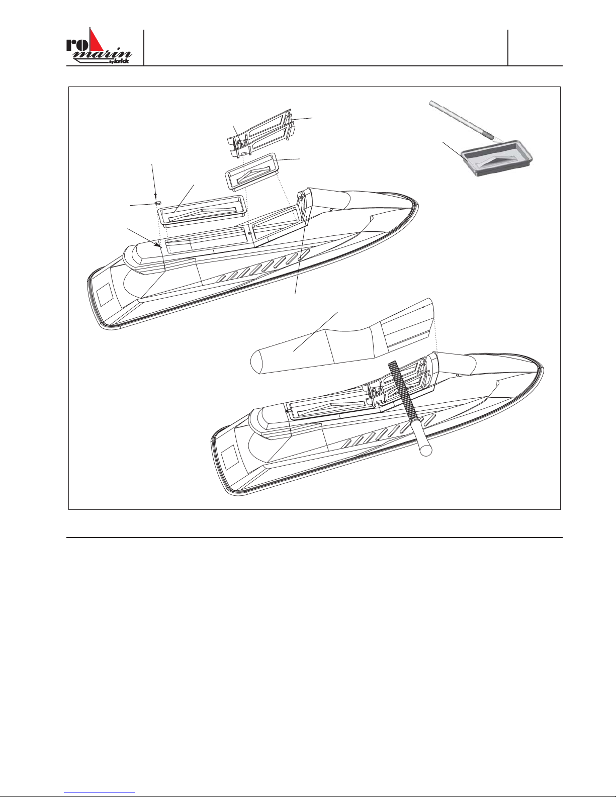
Ebenso die hintere Lukenöff nung
ausschneiden, jedoch hier ca. 3
mm Rand stehenlassen, damit der
fl ache Deckel 3.2 eine gute Auflage hat. Es empfi ehlt sich hierzu
auch, die Ecken der Schnittkante
mit 2 mm zu bohren und dann
zwischen den Bohrungen entlang
einem Lineal zu ritzen, bis das
Teil herausfällt.
Bohren Sie auch die Löcher für das 5 mm Röhrchen, in das die Rückspiegel eingesetzt werden.
Zum Schluss wird noch die Sitzbank entlang der Markierungslinien beschnitten. Hierzu verwenden Sie ein Modellbaumesser,
ritzen ca. 3 mm entfernt von der Markierungslinie mit mehreren Messerzügen an und knicken dann ebenso das Material um.
Der Rest wird dann mit Schleifpapier passend zum Rumpfoberteil abgeschliff en.
28 mm
Ø 5 mm

© Krick Modelltechnik, Germany, Stand 27.11.2017 5
Nr.
ro1266
Bau- und Bedienungsanleitung
Sea-Jet Evolution
Baustufe 0.1 Bohrungen und Abfl achungen
Bohren Sie in die Wellenhosen der Rumpfunterschale die beiden 6 mm Bohrungen für die Stevenrohre. Sie können diese mit
einem kleineren Bohrer vorbohren und dann mit einer Rundfeile genau passend auff eilen.
Bohren Sie jeweils in die Seite der Rumpfunterschale rechts und links je ein 4 mm Loch für den Kühlwasser-Austritt
jedes Motors.
Nun werden noch in die Rumpfunterseite die beiden 4 mm Bohrungen für den Kühlwasser-Eintritt rechts und links zwischen die
Wellenhosen gesetzt.
Die Ruderwelle 2.10a muss noch
mit ihren um 90° versetzten Abfl achungen versehen werden. Dies
ist mit einer Vierkant-Schlüsselfeile
sehr einfach erledigt. Die Abfl achungen dienen dazu, dass die
Madenschraube im Ruder und der
Ruderhebel im Stellring gut auf
der Ruderwelle festsitzen und sich
das Ruder nicht verstellen kann.
Die Breite der Abfl achung sollte
mindestens 3 mm betragen.
Das Ruderblatt 2.10 muss nur an der Oberkante geringfügig modifi ziert werden. Feilen Sie lediglich
die überstehende Nase etwas schräg nach unten ab, wie die Schraffi erung an nebenstehender
Zeichnung zeigt.
Die Ruderwelle 2.10a kann nun in das Ruder mit der unteren Abfl achung nach hinten eingesteckt
werden. Von hinten wird nun ein Innensechskant-Gewindestift M3 x 5 mm in das Ruderblatt geschraubt und auf der Abfl achung der Ruderwelle festgezogen.
Wenn Sie nun von hinten auf das Ruder schauen, sollte die obere Abfl achung rechts zu sehen
sein.
250 mm
33 mm
35 mm
20 mm
Ø4 mm
6 mm
6 mm
5 mm
7 mm
2.10a
abfeilen
2.10
6 © Krick Modelltechnik, Germany, Stand 27.11.2017
Bau- und Bedienungsanleitung
Sea-Jet Evolution
Nr.
ro1266
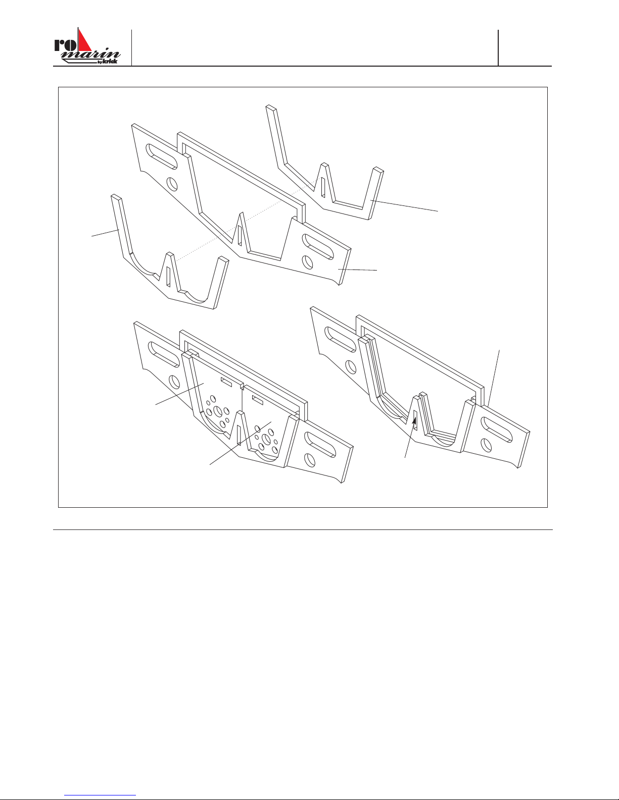
Baustufe 1
1.1
1.3
1.2
1.4
1.4
“S”
1.1 - 1.3
Stck. Bezeichnung, Maße in mm Material Stück
1.1 Motorspant, 3 La 1
1.2 Aufdopplung vorn, 3 La 1
1.3 Aufdopplung hinten, 3 La 1
1.4 Motorträger, 3 La 2
- Die Aufdopplungen 1.2 und 1.3 auf den Motorspant 1.1 kleben. Darauf achten, dass die Unterkanten bündig verlaufen. Zum
Zentrieren kann ein Rest der Laserplatte in den Schlitz “S” geschoben werden. Rest nicht mit verkleben.
- Die Klebestelle gut aushärten lassen.
- Die Motorträger 1.4 von oben in das Spantengerüst einschieben, nicht verkleben. Die Träger müssen herausnehmbar bleiben.
© Krick Modelltechnik, Germany, Stand 27.11.2017 7
Nr.
ro1266
Bau- und Bedienungsanleitung
Sea-Jet Evolution
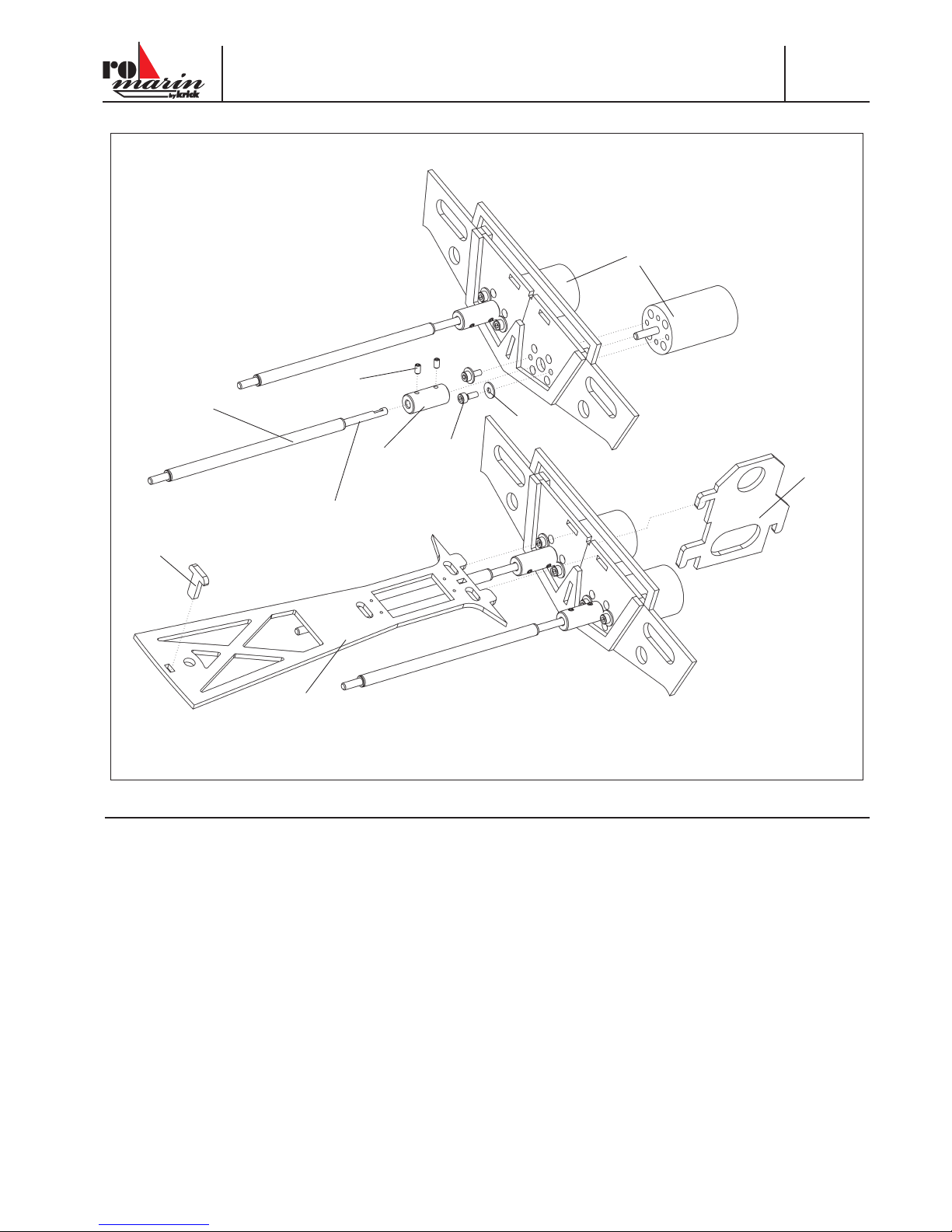
Baustufe 1
1.14
1.5
1.6
1.7
1.11
1.9
1.8
1.12
1.13
1.10
Stck. Bezeichnung, Maße in mm Material Stück
1.5 Motor 2 AS
1.5a Motorkühlschlange Alu 2 AS
1.6 Scheibe, Ø 3,2 Metall 4 AS
1.7 Innensechskantschraube, M 3 x 8 Metall 4 AS
1.8 Kupplung, Ø 11 x 25 Alu 2 AS
1.9 Innensechskant-Madenschraube, M 3 x 5 Metall 4 AS
1.10 Schiff swelle, Ø 4 x 168 2
1.11 Stevenrohr, Ø 6 x 120 2
1.12 Servobord, 3 La 1
1.13 Riegel, 3 La 1
1.14 Zentrierstück, 3 La 1
- Die Motoren 1.5 mit Wasserkühlschlange 1.5a versehen und mit Scheiben 1.6 und Schrauben 1.7 einbauen.
- Die Kupplungen 1.8 mit Innensechskantmadenschrauben 1.9 versehen und auf den Motorwellen festsetzen.
- Wellenanlage 1.10, 1.11 einkuppeln.
- Das Servobord 1.12 in die Motorträger schieben und mit dem eingeschobenen Riegel 1.13 sichern. Teile 1.12 und 1.13 nicht
verkleben.
- Das Zentrierstück 1.14 einschieben.
8 © Krick Modelltechnik, Germany, Stand 27.11.2017
Bau- und Bedienungsanleitung
Sea-Jet Evolution
Nr.
ro1266
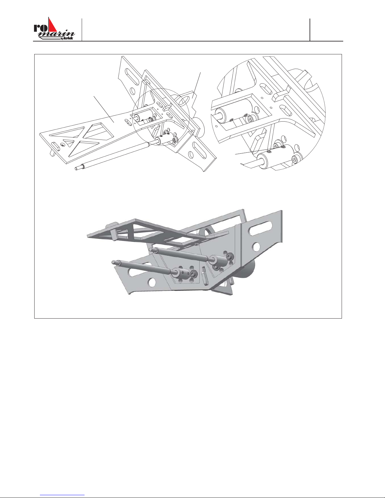
Baustufe 1
1.13
1.9
1.12
Hinweis zu den Motorträgern 1.4, Motoren 1.5
Um die Motoren bei Wartungsarbeiten aus dem fertigen Modell ausbauen zu können, bleiben die Motorträger 1.4 lösbar. Der Steg
über den Trägern wird nach Einbau der Antriebseinheit in den Rumpf entfernt.
Zum Ausbau den Riegel 1.13 zuerst nach oben dann nach vorn aus den Spanten ziehen und lösen.
Madenschrauben 1.9 lösen. Motoren auskuppeln. Motorträger 1.4 mit dem Servobord 1.12 nach oben ziehen und Motorträger
lösen.

© Krick Modelltechnik, Germany, Stand 27.11.2017 9
Nr.
ro1266
Bau- und Bedienungsanleitung
Sea-Jet Evolution
Baustufe 1, 2
1.15
1.17
1.18
1.16
1.19
1.13
1.15
2.3
2.4
2.4
2.2
2.1
2.5
2.5
1.18
Stck. Bezeichnung Maße in mm Material Stück
1.15 Akkurahmen 3 La 1
1.16 Spant vorn 3 La 1
1.17 Spant hinten 3 La 1
1.18 Akkuhalter 3 La 2
1.19 Zwischenwand 3 La 1
- Die Spanten 1.16 und 1.17 sowie die Akkuhalter 1.18 in den Akkurahmen 1.15 schieben und verkleben.
- Die Zwischenwand 1.19 wird nur in den Rahmen gesteckt. Dadurch können Akkus verschiedener Größen verwendet werden.
- Den Akkurahmen in den entsprechenden Zapfen des Riegels 1.13 stecken, nicht verkleben.
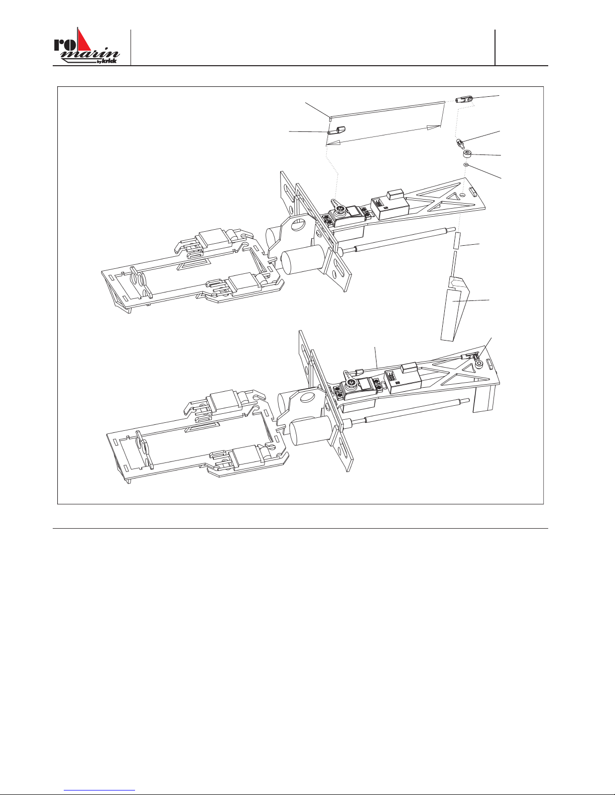
Baustufe 2
Stck. Bezeichnung Maße in mm Material Stück
2.1 Servo mit Befest. material 1, n.e.
2.2 Servohebel 1, bei 2.1
2.3 Empfänger 1, n.e.
2.4 Fahrtregler 1 oder 2, n.e.
2.5 Klettband Flausch + Haken je 3
Die hier verwendeten Teile können sich etwas unterscheiden, je nachdem, welche Antriebsversion verwendet wird. Bei dem
Standard-Antriebssatz mit Bürstenmotoren wird nur ein Fahrtregler für beide Motoren verwendet, der nicht wassergekühlt ist. Bei
der Brushlessversion wird pro Motor ein Fahrtregler benötigt, der auch wassergekühlt wird. Daher sind in der Abbildung auch zwei
Fahrtregler dargestellt.
- Servo 2.1 mit Befestigungsmaterial einsetzen. Löcher Ø 1,5 mm bohren, Servo verschrauben.
- Beschnittenen Servohebel 2.2 auf Ø 2 mm aufbohren und montieren.
- Den Empfänger 2.3 und die Regler 2.4 mit Klettbandstücken 2.5 befestigen.
10 © Krick Modelltechnik, Germany, Stand 27.11.2017
Bau- und Bedienungsanleitung
Sea-Jet Evolution
Nr.
ro1266
Baustufe 2
2.6
2.7
2.8
2.13
2.12
2.11
2.9
2.10
2.6
2.10 - 2.13
148 mm
Stck. Bezeichnung Maße in mm Material Stück
2.6 Rudergestänge Ø 2 Ms 1
2.7 Sicherungsclip Ku-Sp 1
2.8 Kugelpfanne Ku-Sp 1
2.9 Ruderkoker Ø 5 x 19 Ms 1
2.10 Keilruder mit montierter Welle Ku-Sp 1
2.11 O-Ring Gummi 1
2.12 Stellring Ø 4 x 5 Metall 1
2.13 Kugelbolzen 18 lang Ms 1
- Das Rudergestänge 2.6 nach Maßangabe abwinkeln, Sicherungsclip 2.7 aufdrücken.
- Den Kugelkopf 2.8 auf das Gestänge aufdrehen.
- Die Ruderanlage probeweise einbauen.
- Den Ruderkoker 2.9 in das Servobord 1.12 einstecken.
- Das Keilruder 2.10 von unten einsetzen, O-Ring 2.11 auf den Ruderschaft schieben.
- Stellring 2.12 aufschieben, Kugelbolzen 2.13 eindrehen und über der Abfl achung des Ruderschafts festziehen.
- Servo in Neutralstellung bringen und vorbereitetes Rudergestänge einhängen.
- Den Kugelbolzen 2.13 lösen und Ruder 2.10 mit Ruderkoker 2.9 ausbauen.
Anderes keilruder siehe ro1477
Die Darstellung zeigt den Einbau des Brushless-Antriebes mit zwei Fahrtreglern und ohne Wasserkühlung.
© Krick Modelltechnik, Germany, Stand 27.11.2017 11
Nr.
ro1266
Bau- und Bedienungsanleitung
Sea-Jet Evolution
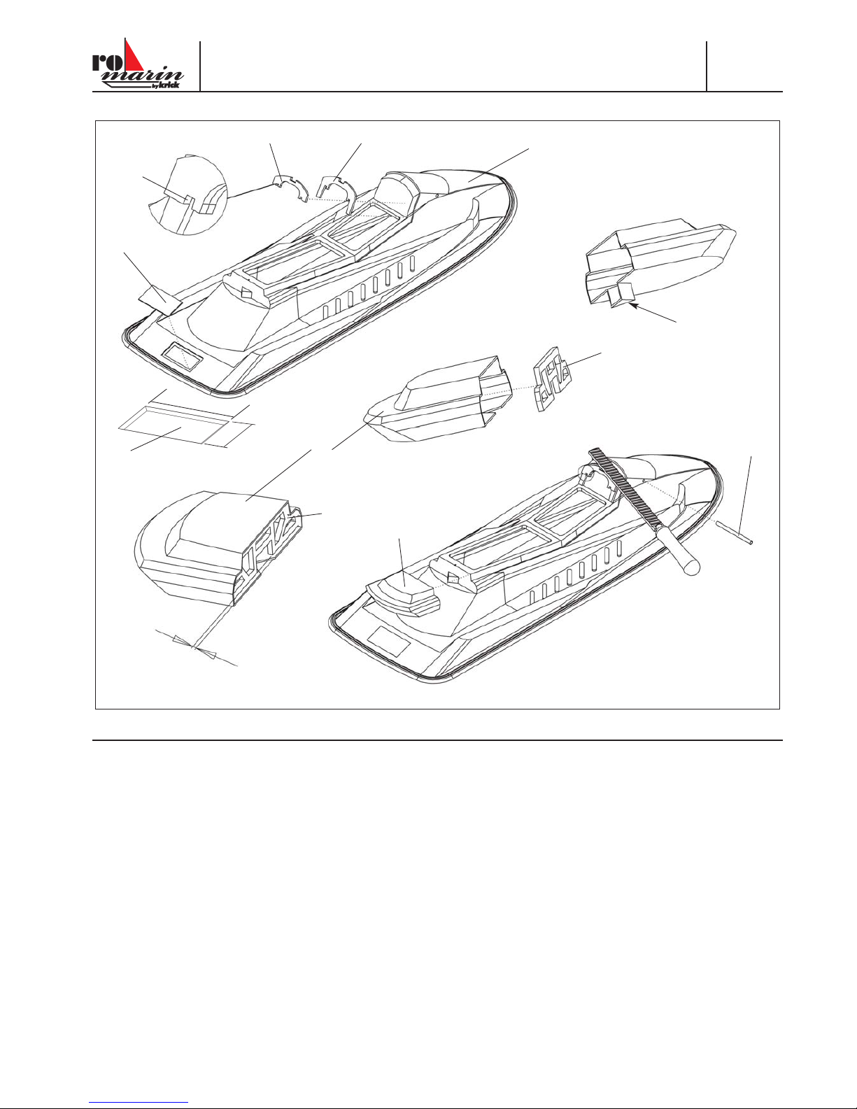
Baustufe 3
3.1
3.2
3.4
3.3
3.5
3.6
3.7
3.7
3.6
“a”
1,5 mm
3.2
“D”
“E”
59 mm
29 mm
Stck. Bezeichnung Maße in mm Material Stück
3.1 Deck 1,5 Tzt schwarz 1
3.2 Montagedeckel 1,5 ABS schwarz 1 Rest
3.3 Spant 3 La 1
3.4 Aufdopplung 3 La 1
3.5 Führungsrohr, Spiegel Ø 4,2 x Ø 5 x 69 Alu 1
3.6 Heckteil schwarz 1,5 Tzt 1
3.7 Spant 3 La 1
- Das schwarze Restmaterial auf ein Rechteck von 59 x 29 mm zurechtschneiden und für den Montagedeckel 3.2 in die Öff nung
des Decks 3.1 probeweise einsetzen. Deckel 3.2 durch Anschrägen der Ränder in die Öff nung einpassen, einsetzen und mit
einem Streifen Tesa sichern - Detail “D”. Der Deckel wird später mit Dekor fi xiert.
- Spant 3.3 und Aufdopplung 3.4 aufeinanderkleben. Dabei gemäß Detailansicht “E” darauf achten, dass die Ausschnitte “a”
deckungsgleich aufeinanderliegen.
- Spant 3.3 so auf das Deck kleben und befeilen, dass er mit der Wölbung bündig abschließt.
- Das Röhrchen 3.5 zur Aufnahme der Spiegel einkleben.
- Am Heckteil 3.6 die untere Anformung plan zum Boden abschneiden - Pfeil beachten.
- Den Spant 3.7 in das Heckteil kleben, dabei rundum einen Abstand von ca. 1,5 mm zum Rand einhalten.
- Das Heckteil an das Deck setzen und anpassen. Zum Verkleben des Heckteils den Silikonkleber verwenden.
12 © Krick Modelltechnik, Germany, Stand 27.11.2017
Bau- und Bedienungsanleitung
Sea-Jet Evolution
Nr.
ro1266
Baustufe 3
3.9
3.8
3.10
3.11
3.15
3.12
3.14
3.17
3.16
3.16
3.18
3.13
3.5
3.10
3.9
3.8
3.8a
Stck. Bezeichnung Maße in mm Material Stück
3.8 Sechskantmutter M6 Metall 1
3.8a Abdeckscheibe 3 La 1
3.9 Distanzscheibe Innensechskant 3 La 1
3.10 Gegenlager 3 La 1
3.11 Schraubenplatte 3 La 1
3.12 Spant mitte, 3 La 1
3.13 Längsholm, 3 La 2
3.14 Spant hinten, 3 La 1
3.15 Spant vorn, 3 La 1
3.16 Schraubenführung oben 3 La 2
3.17 Schraubenführung unten 3 La 1
3.18 Schraube M6 x 25 Nylon 1
- Die Abdeckscheibe 3.8a mit der Distanzscheibe 3.9 und diese mit dem Gegenlager 3.10 verkleben.
- Sechskantmutter 3.8 einlegen und fertiges Gegenlager von unten auf die hintere Fläche des Stegs kleben.
- Das Röhrchen 3.5 von unten mit Acrylit-Klebstoff vermuff en - Pfeil. Der Unterbau 3.11 - 3.17 wird zunächst nur zusammengesteckt.
- Die Schraubenplatte 3.11 zwischen die Längsholme 3.13 stecken.
- Die Spanten 3.12, 3.14 und 3.15 von unten einschieben.
- Die Schraubenführungen 3.16 von oben, 3.17 von unten einsetzen. Schraube 3.18 in die Platte schieben.
© Krick Modelltechnik, Germany, Stand 27.11.2017 13
Nr.
ro1266
Bau- und Bedienungsanleitung
Sea-Jet Evolution
Baustufe 4
4.1
4.2
3.11 - 3.17
4.3
4.4
4.5
1,5 mm
3.3 / 3.4
3.18
4.1, 4.2
Stck. Bezeichnung Maße in mm Material Stück
4.1 Deckel, schwarz 1,5 Tzt 1
4.2 Deckel, schwarz 1,5 Tzt 1
4.3 Vorreiber 3 La 1
4.4 Schraube Ø 2,2 x 9,5 1
4.5 Sitzbank, schwarz 1,5 Tzt 1
- Die Kanten der Decksöff nungen rundum mit Schleifpapier glätten.
- Den oberen Rand der Deckel 4.1 und 4.2 jeweils rundum beschneiden und abknicken. Rand beschleifen und Deckel einsetzen.
- Das Ø 1,5 mm Loch nach Markierung bohren. Den Vorreiber 4.3 mit der Schraube 4.4 drehbar montieren. Schraube 4.4 von
unten mit Acrylit-Klebstoff fi xieren.
- Den vorbereiteten Sitzbank-Unterbau 3.11 - 3.18 aufsetzen und dabei vorn in den Spant 3.3 / 3.4 einrasten lassen. Den Unterbau mit der Schraube 3.18 befestigen.
- Die Sitzbank 4.5 probeweise aufsetzen. Die Kanten des Unterbaus beschleifen bzw. befeilen, bis die Sitzbank rundum spaltfrei
auf dem Deck sitzt.
- Den Unterbau am Deck mit quergespannten Klebebandstreifen fi xieren.
- Die Schraube 3.18 entfernen.
- Die Sitzbank aufsetzen und ebenfalls mit Klebebandstreifen am Deck fi xieren.

14 © Krick Modelltechnik, Germany, Stand 27.11.2017
Bau- und Bedienungsanleitung
Sea-Jet Evolution
Nr.
ro1266
Baustufe 4
Ø6mm
Ø4mm
4.7
4.6
4.8
“H”
Stck. Bezeichnung Maße in mm Material Stück
4.6 Verstärkung 3 La 1
4.7 Lenker Ku-Sp 1
4.8 Schraube Ø 2,2 x 11 Stahl 2
- Von unten einen 4 mm Bohrer d urch die Mutter 3.8 schieben. Das Ø 4 mm Loch von unten durch die Sitzbank durchbohren.
- Das Loch von oben in der Sitybank auf Ø 8 mm aufreiben.
- Sitzbank abnehmen und das Loch im Deck auf 6 mm aufbohren.
- Die Schraube 3.18 wieder in den Unterbau drehen, die Klebebandstreifen entfernen.
- Die Längsholme 3.13 und die Spanten 3.14, 3.15 an den Oberkanten mit Acrylit-Klebstoff einstreichen, die Sitzbank aufsetzen
und ausrichten.
- Die Sitzbank mit Klebebandstreifen erneut fi xieren, Modell auf den Rücken drehen und Klebestelle gut aushärten lassen.
- Die Schraube 3.18 von oben durch die Ø 8 mm Bohrung lösen, Sitzbank abnehmen.
- Die Verstärkung 4.6 von unten in die Sitzbank kleben. Den angeformten Hilfssteg “H” nicht mit Klebstoff einstreichen. Der Steg
muss bündig mit der Vorderkante der Sitzbank abschließen.
- Die Löcher der Verstärkung mit Ø 2 mm durchbohren und den Lenker 4.7 mit den Schrauben 4.8 befestigen.
Ø 6 mm
Ø 8 mm

© Krick Modelltechnik, Germany, Stand 27.11.2017 15
Nr.
ro1266
Bau- und Bedienungsanleitung
Sea-Jet Evolution
Baustufe 4
4.9
4.9
3.18
“H”
Stck. Bezeichnung Maße in mm Material Stück
4.9 Spiegel Ku-Sp 2
- Die Längsholme und Spanten des Unterbaus mit Sekundenkleber untereinander verkleben.
- Teil 3.17 muss lösbar bleiben - nicht verkleben. Falls die Schraube 3.18 einmal ausgewechselt werden muss, Teil 3.17 nach
unten schieben und die Schraube 3.18 herausziehen.
- Den Hilfssteg “”H” der Verstärkung 4.6 wegschneiden - siehe Detailzeichnung.
- Die Spiegel 4.9 mit Acrylit-Klebstoff in das Röhrchen 3.5 kleben und ausrichten.

16 © Krick Modelltechnik, Germany, Stand 27.11.2017
Bau- und Bedienungsanleitung
Sea-Jet Evolution
Nr.
ro1266
Baustufe 5
2.9
1.12
1.1
1.13
12 mm
0.5 mm
5.1
Stck. Bezeichnung Maße in mm Material Stück
5.1 Rumpf Tz 1
5.1 a Kühlwassereinlassrohr Ø 4 x 25 Ms 2
5.1 b Kühlwasserauslassrohr Ø 4 x 25 Ms 2
5.1 c Verstärkungsring La 4
5.1 d Kühlwasserschlauch Ø 3,5 x 5,5 Silikon 1 AS
5.1 e Wasserkühlschlange Alu 2 AS
Einbau des Antriebs
Es wird mit Acrylit-Klebstoff geklebt.
- Die Kühlwassereinlässe 5.1 a nach Zeichnung schräg feilen und in die beiden Bohrungen im Wellentunnel einkleben. Die
Abschrägung des Röhrchens muss dabei mit der Öff nung nach vorne aus dem Rumpfboden herausragen, damit während der
Fahrt das Kühlwasser aufgenommen wird (siehe Schnittzeichnung). Der Verstärkungsring wird von innen mit eingeklebt.
- Ebenso die Kühlwasserauslässe von innen links und rechts in die vorgebohrten Löcher einkleben so dass ein kleiner Rand
außen übersteht. Die Verstärkungsringe werden von innen mit eingeklebt.
- Die Kühlwasserschlangen auf die Motoren stecken. Die Motoranschlusskabel sollten hier auch schon angelötet sein.
- Die vorbereitete Antriebseinheit in den Rumpf 5.1 einsetzen.
- Den Ruderkoker 2.9 so einschieben, dass er unten 0,5 mm übersteht, noch nicht verkleben.
- Den Motorspant 1.1 und die Hinterkante des Servobords 1.12 im Rumpf verkleben. Das Servobord biegt sich in eingebautem
Zustand geringfügig durch. Den Riegel 1.13 nicht verkleben.
- Die Stevenrohre von innen dicht verkleben. Den Überstand von 12 mm beachten.
5.1a
5.1 c
hinten vorne
5.1
5.1b
5.1 c
innen
außen

© Krick Modelltechnik, Germany, Stand 27.11.2017 17
Nr.
ro1266
Bau- und Bedienungsanleitung
Sea-Jet Evolution
Baustufe 5
1.15
1.19
5.4
5.4
1.13
5.3
5.2
2.10
Stck. Bezeichnung Maße in mm Material Stück
5.2 Kontermutter M4 2
5.3 Schiff sschraube, re. + li. je 1
5.4 Klettband 2 n.e.
- Die Kühlwasserschläuche für jede Motorseite zuschneiden und in folgender Reihenfolge anschließen:
Einlass –> Fahrtregler (wenn wassergekühlt) –> Motor –> Auslass
- Den Montagesteg des Motorspants 1.1 absägen.
- Die Kontermuttern 5.2 und die Schiff sschrauben 5.3 auf die Schiff swellen aufdrehen. Schiff sschrauben gegen die Muttern
kontern.
- Das Keilruder 2.10 in den Ruderkoker schieben, O-Ring 2.11 aufschieben, Ruder mit Stellring 2.12 sichern.
- Das Ruder ausrichten. Das Ruder muss von hinten und von der Seite gesehen senkrecht nach unten stehen. Falls erforderlich,
den Sitz des Ruderkokers im Servobord nacharbeiten. Erst bei korrekt stehendem Ruder den Ruderkoker im Rumpf und am
Servobord verkleben.
- Den Akkurahmen 1.15 einhängen. Die Spanten 1.16 - 1,18 im Rumpf verkleben. Rahmen nicht an der Verriegelung 1.13 verkleben.
- Die Zwischenwand 1.19 bleibt steckbar, ebenfalls nicht verkleben.
- Die Empfangsanlage wieder komplett einbauen. Rudergestänge montieren.
- An den Positionen 5.4 können Klettbänder oder Kabelbinder in die Akkuhalter 1.18 einfädelt werden, damit der Akku fi xiert ist.

18 © Krick Modelltechnik, Germany, Stand 27.11.2017
Bau- und Bedienungsanleitung
Sea-Jet Evolution
Nr.
ro1266
Baustufe 5
Zusammenkleben des Rumpfs
- Den Silikonkleber rundum nicht zu dick und gleichmäßig in der Nut des Decks auftragen.
- Den Rumpf einsetzen, übergequollenen Kleber abstreichen.
- Die Einheit in den Bootsständer setzen und mit mehreren Klammern zusammenspannen. Der Rumpf muss auf dem Bootsständer gleichmäßig aufl iegen. Rumpf und Deck dürfen nicht gegeneinander verspannt sein.
- Kleber gut aushärten lassen.
Elektrische Anschlüsse nach Schaltplan Seite 23
- Die einzelnen Komponenten der RC-Anlage und des Antriebs gemäß dem richtigen Schaltplan für Standard- oder Brushlessantrieb anschließen. Zum Verkabeln der Antriebe untereinander entsprechendes Kabel sowie Steckverbindungen vorsehen.
- Die Regler werden mit einem V-Kabel “V-K” am Empfänger angeschlossen. (nur bei der Brushless-Version)
- Bei Verwendung von zwei Reglern muss an einem Reglerkabel die rote Plus- Leitung aus dem Steckergehäuse gezogen und
isoliert werden.

© Krick Modelltechnik, Germany, Stand 27.11.2017 19
Nr.
ro1266
Bau- und Bedienungsanleitung
Sea-Jet Evolution
Baustufe 5
5.5
5.5
Stck. Bezeichnung Maße in mm Material Stück
5.5 Gummi-Profi lschnur 1
5.6 Fahrakku 1, n.e.
- Die Gummi-Profi lschnur 5.5 ist kürzer als der Umfang der Rumpfkante, da sie dehnbar ist und gedehnt über den Rand gezogen wird. An der Stoßstelle mit Sekundenkleber verkleben.
Achtung: Die Schnur darf nicht in sich verdreht sein. Klebestelle gut aushärten lassen.
- In die Nut der Gummischnur wenig Silikon einbringen und die Schnur mit der Klebestelle hinten beginnend um den Rand ziehen.
Funktionsprobe und Austrimmen
- Modell in den Bootsständer setzen. Knüppel und Trimmungen am Sender in Neutralstellung bringen. Der Gasknüppel muss
sich in der Stellung „Motor aus“ befi nden. Sender einschalten.
- Fahrakku 5.6 einlegen, am Reglerkabel anschließen und sichern.
- Das Ruder muss sich in Mittelstellung befi nden. Falls erforderlich, Rudergestänge nachjustieren.
- Rechts/Links-Funktion prüfen. Bei vertauschter Laufrichtung des Servos Servo-Reverse des Senders betätigen
- Motorlauf prüfen. Die Motoren müssen bei Vorwärtsfahrt gemäß Pfeilrichtung drehen. Falls erforderlich, die Laufrichtung des
falsch herum drehenden Motors durch Vertauschen zweier Kabel zwischen Motor und Regler ändern.
- Achtung bei Motor-Probeläufen: Motoren immer nur kurz und langsam laufen lassen.
- Verbindung Akku - Regler trennen, erst dann den Sender ausschalten.
- Vorsicht: Bei allen Arbeiten am Boot bei angeschlossenem Fahrakku immer darauf achten, dass die Schiff sschrauben frei drehen können. Nicht mit den Händen in den Drehkreis der Schiff sschrauben geraten - Verletzungsgefahr.
der Zeichnung den
Schnitt vorne entfernen

20 © Krick Modelltechnik, Germany, Stand 27.11.2017
Bau- und Bedienungsanleitung
Sea-Jet Evolution
Nr.
ro1266
Baustufe 6
3.2
6.3
6.3
6.1
6.1
6.2
6.2
6.2
5.6
5.4
Endarbeiten und Fahrerfi gur
- Fahrakku 5.6 einlegen und mit den Klettbändern 5.4 sichern.
- Die endgültige Sicherung des Deckels 3.2 erfolgt mit dem Schriftzug “Sea-Jet Evolution“ des Dekorbogens. So bleiben Ruder
und Rudergestänge für Wartungsarbeiten zugänglich.
Fahrerfi gur
Stck. Bezeichnung Maße in mm Material Stück
6.1 Körper 1
6.2 Bein re + li je 1
- Die fertigungsbedingten Angüsse an der Fahrerfi gur glattschleifen - Pfeile
- Die Beine an den Körper der Fahrerfi gur kleben, viereckige Anformungen beachten.

© Krick Modelltechnik, Germany, Stand 27.11.2017 21
Nr.
ro1266
Bau- und Bedienungsanleitung
Sea-Jet Evolution
Baustufe 6
6.3
Ø6mm
6.4
4.7
Stck. Bezeichnung Maße in mm Material Stück
6.3 Arme je 1
6.4 Klettband Flausch + Haken je 1
- Die Hände der Arme jeweils innen mit Ø 4 mm beginnend stufenweise auf 6 mm aufbohren bzw. auff eilen.
- Arme beidseitig an den Lenker 4.7 stecken. Vorbereitete Figur auf der Sitzbank positionieren und Arme ansetzen.
- Figur ausrichten und Arme verkleben.
- Die Sitzbank lösen, den Lenker 4.7 von unten
-abschrauben.
- Die Fahrerfi gur kann jetzt an den Übergängen zwischen Körper und Extremitäten gespachtelt, verschliff en und lackiert werden.
- Die Figur auf der Sitzbank mit Klettbandstreifen 6.4 fi xieren.
- Die restlichen Dekorbilder nach Kartonagen-Abbildung anbringen.
- Vor Aufnahme des Fahrbetriebs die Schiff swellen mit romarin Wellenfett versehen. Dazu an der Kupplung die hinteren Schrauben 1.9 lösen, Wellen nach hinten herausziehen.
- Fett in die Stevenrohre füllen und Wellen wieder einbauen.

22 © Krick Modelltechnik, Germany, Stand 27.11.2017
Bau- und Bedienungsanleitung
Sea-Jet Evolution
Nr.
ro1266
Die Jungfernfahrt
Nach Laden des Akkus ist das Modell bereit zur Jungfernfahrt.
Einen nicht zu windigen Tag und ein größeres Gewässer aussuchen.
Das Modell in den Bootsständer setzen.
Immer zuerst den Sender, dann die Empfangsanlage einschalten.
Cockpit und Deckel aufsetzen und rundum abkleben.
Nochmals eine Funktionsprobe durchführen.
Gewöhnen Sie sich zunächst bei mittlerer Fahrgeschwindigkeit an die Lenkreaktionen des Modells.
Zum Abbremsen Gas herausnehmen.
Muss der Geradeauslauf am Sender nachgetrimmt werden, nach Beendigung des Fahrbetriebs das Lenkgestänge entsprechend
verstellen. So steht wieder für beide Seiten der volle Trimmweg zur Verfügung.
Das Modell ist sehr schnell. Beim Fahren zum Ufer oder in der Nähe von Hindernissen, zum Beispiel Bojen, beachten, dass der
Motor immer rechtzeitig heruntergeregelt wird. Nicht in der Nähe von Schwimmern oder Booten fahren.
Wird das Modell langsamer, ist in Kürze der Akku leer. In diesem Fall sofort ans Ufer fahren.
Nach Beendigung des Fahrbetriebs Boot öff nen, die Verbindung des Akkus zum Regler trennen, erst dann Sender ausschalten.
Akku und Motoren bei geöff netem Boot auskühlen, Boot innen trocknen lassen (Kondenswasser).
Von Zeit zu Zeit die Fettfüllung der Stevenrohre erneuern.
Klaus Krick Modelltechnik
Technische Änderungen vorbehalten

© Krick Modelltechnik, Germany, Stand 27.11.2017 23
Nr.
ro1266
Bau- und Bedienungsanleitung
Sea-Jet Evolution
1.5
1.5
2.1
2.3
2.4
2.4
5.6
“V-K”
2.10
5.4
5.4
Akku
7,2 - 8,4 V
Akku
7,2 - 8,4 V
+
-
+
-
+
-
an/aus
on/o
Fahrtregler
ESC
BAT
CH1
CH2
1
2
Zum Ladegerät
To charger
Min. Empfänger
2-Kanal
min.
Receiver
2 ch.
CH3
CH4
CH5
Schaltplan für Standardantrieb (Bürstenmotoren und ein Fahrtregler)
Schaltplan für Brushlessantrieb (Bürstenlose Motoren mit zwei Fahrtreglern)

Irrtum und technische Änderungen vorbehalten. Copyright Klaus Krick Modelltechnik 2017.
Kopie und Nachdruck, auch auszugsweise, nur mit schriftlicher Genehmigung von Klaus Krick Modelltechnik
Klaus Krick Modelltechnik
Industriestr. 1
75438 Knittlingen
Germany
Telefon: +49 (0)7043 9351-0
www.krick-modell.de

© Krick Modelltechnik, Germany, Version 28.11.2017
Sea Jet Evolution
No. ro1266
Assembly and operating instructions
Notice de montage et de pilotage
The picture shows the model with brushless drive
La photo montre le modèle avec une propulsion brushless

2 © Krick Modelltechnik, Germany, Version from 28.11.2017
Assembly and operating instructions
Sea-Jet Evolution
No.
ro1266
Technical data:
Length --------------------------------------- approx. 685 mm
Width ----------------------------------------- approx. 240 mm
Height ---------------------------------------- approx. 370 mm
Displacement/weight --------------------- approx. 2100 g
For additional items necessary to complete the model, please
see separate accessory sheet.
For tools and other useful items, please see the Krick main
catalogue.
Assembly sequence and instructions
The section numbering represents general assembly sequence.
Please make yourself familiar with the instruction notes, parts
list and illustrations before and during each assembly stage.
At the beginning of the instruction a drawing illustrates the
laser cut plastic parts and at the end you can fi nd an electrical
schematic diagram.
Vacuum formed (vac form) parts
After trimming the edges of the vac form parts, smooth all
edges with sandpaper.
Holes are to be drilled at the marked locations on these parts
or regarding the measures shown on the drawings.
Laser-Cut Parts
Only remove the parts from the sheet that you will need for a
particular assembly stage.
Please identify the parts and number them accordingly. This
will ease assembly later on.
Please remove the bars of the parts with a sharp modeling
knife after removing them from the lasersheet.
Please try to put all parts together before gluing, they should all
fi t together easily, if not, please use a knife, triangular fi le and
sanding block to get a perfect fi t.
Adhesives and bonding
Before assembling, roughen all areas to be adhered with sandpaper.
Only use the adhesives recommended in these instructions.
Please read and take note of the instructions given by the
adhesive manufacturer.
To bond the deck to the hull, use a Silicone adhesive or silicone sealant. For this gluing process, please only use this glue,
so that the connection can be reopened later.
Please note: this adhesive needs 24 hours to fully cure.
Before bonding parts, make a dry run to check the fi t of all
parts to be bonded.
When using a Acrylic glue, don’t be tempted to make a large
glue fi llet, you will get a better joint if you evenly spread it out
thin and evenly before joining the parts.
All hull joints where water ingress is likely (rudder bearing,
Propshaft) should be sealed with a fi llet of Acrylic glue on the
inside where they exit the hull.
After bonding, clamp all parts in position with bulldog clamps or
clothes pegs.
Only use small quantities of instant glue (cyanoacrylate) applied on the end of a needle or length of wire.
To avoid contamination of glue joints during assembly, the
model will be dry assembled without grease fi rst. Greasing and
lubrication will be made before test running.
Insulate all the solder joints with a small length of heat shrink
tubing to prevent short circuits.
Left and Right orientation is seen in the direction of travel.
All dimensions, weights are in the metric system.
Radio control system
You will need a 2-channel radio system with one rudder servo
and one or two electronic speed controller (ESC) with Battery
Eliminator Circuit (BEC).
It is best to have the radio available before you start assembly,
so you can orient your radio installation to suit the model. If you
are using a diff erent radio to that recommended, please ensure
that you make the necessary adjustments to sizes and layout
during the assembly.
Please follow the radio manufacturers guidance for installation
of the receiver.
Set the rudder steering servo to its central neutral position
(transmitter stick and trim lever in the middle). You may need to
remove or change the servo arm or disc.
Before switching on the model, always ensure throttle stick is
in “motor off ” position. You can then connect the drive pack to
power up the model.
When switching off , always remove drive battery pack before
turning transmitter off .
Painting
The painting of pre fi nished hull and deck is not necessary.
Key to material abbreviations used in parts list/
instructions
n.i. = not included
Br = Brass
Pl = Plasticf
PM = Plastic moulding
Vac = vac formed part
LC = Laser-Cut part
D = diameter

© Krick Modelltechnik, Germany, Version from 28.11.2017 3
No.
ro1266
Assembly and operating instructions
Sea-Jet Evolution
Alu = aluminium
PS = Included in the power set and not in the model kit.
Boat Stand
The boat stand is included as a vac form part; you can stiff en
its structure by bonding a plate of 4 mm plywood (not included)
to the bottom of the stand.
Stage 0 Preliminary work on diff erent parts
Cut off the hatched marked ends on the vacuum formed parts. To do this, take the fuselage bottom shell and with the help of a
cutter knife, scratch several times in the outermost inner edge until you can fold the protruding material outwards. After bending
back and forth the material kinks at the desired edge.
For the upper part of the hull proceed in the same way as before for the lower part of the hull. Here, however, you have to exercise
a little more caution, as the edge for scoring easily merges into the radius, which represents the adhesive bond with the lower
shell. In this arched edge should not be scratched as possible. Just score along the outermost edge and bend the edge as before.
Furthermore, the two openings in the area of the seat must be cut out. Here you scratch several times from above in the lower
edge of the opening until the part falls out by itself. Please do not throw this leftovers away. It is still needed from this a remnant
piece for the rear hatch cover 3.2.
Also cut out the rear hatch opening, but leave here about 3 mm edge, so that the fl at lid 3.2 has a good edition. It is also advisable
to drill the corners of the cut edge with 2 mm and then to score between the holes along a ruler until the part falls out.
Also drill the holes for the 5mm tube into which the rearview mirrors are inserted.
Finally, the seat is trimmed along the marking lines. To do this, use a model knife, scrape about 3 mm away from the marking line
with several knife pulls, and then fold over the material as well.
The remainder is then sanded with sandpaper matching the fuselage shell.
Stage 0.1 Install holes and fl ats
Drill the two 6 mm holes for the stern tubes into the shells of the fuselage bottom shell. You can pre-drill them with a smaller drill
bit and then fi le them with a round fi le.
Drill a 4 mm hole on each side of the fuselage bottom shell for the cooling water outlet of each motor.
Now the two 4 mm holes for the cooling water inlet are placed in the fuselage underside, right and left between the wave pants.
The rudder shaft 2.10a still needs to be provided with its fl attened by 90° fl attening. This is done very easily with a square key
fi le. The fl ats serve to ensure that the grub screw in the rudder and the rudder lever in the adjusting ring are fi rmly seated on the
rudder shaft and the rudder can not be turned. The width of the fl attening should be at least 3 mm.
The rudder blade 2.10 only needs to be slightly modifi ed at the top edge. Just fi le the protruding nose slightly diagonally downwards, as shown by the hatching on the adjacent drawing.
The rudder shaft 2.10a can now be plugged into the rudder with the lower fl attening to the rear. From behind, a grub screw M3 x 5
mm is now screwed into the rudder blade and tightened on the fl attening of the rudder shaft.
If you now look at the rudder from behind, the upper fl attening should be on the right.

4 © Krick Modelltechnik, Germany, Version from 28.11.2017
Assembly and operating instructions
Sea-Jet Evolution
No.
ro1266
Stage 1
Part No. Descriptions size in mm material required number marks
1.1 Motorformer 3 LC 1
1.2 Doubler front 3 LC 1
1.3 Doubler rear 3 LC 1
1.4 Motor mount 3 LC 2
- Bond the doublers, 1.2 and 1.3 to the motor former, 1.1. Pay attention that the lower edges are all fl ush with each other. To help
alignment of the parts, use a piece of the waste pushed into the slot “S”, clamp in position and remove before the adhesive
cures.
- Allow the joint to harden thoroughly before proceeding
- Slide the motor mount, 1.4 into the former assembly, DO NOT GLUE in place, as this part must remain removable.
Stage 1
Part No. Descriptions size in mm material required number marks
1.5 Motor 2 PS
1.5a Water cooling Alu 2 PS
1.6 Washer Ø 3,2 Metall 4 PS
1.7 Allen screw M 3 x 8 Metall 4 PS
1.8 Coupling, Ø 11 x 25 Alu 2 PS
1.9 Hexagon grub screw M 3 x 5 Metall 4 PS
1.10 Propshaft Ø 4 x 168 2
1.11 Stuffi ng tube Ø 6 x 120 2
1.12 Servo tray 3 LC 1
1.13 Latch plate 3 LC 1
1.14 Center piece 3 LC 1
- Slide water cooling 1.15a onto motor 1.5 and mount with washer 1.6 and screws 1.7 on motor mount 1.4.
- Fit the couplings 1.8 with hexagon socket head screws 1.9 and fi x them on the motor shafts.
- Insert Propshafts 1.10 with stuffi ng tube 1.11 and tighten.
- The servo board 1.12 slide into the motor mount and secure it with the bolt inserted 1.13. Do not stick parts 1.12 and 1.13 together.
- Insert the centering piece 1.14.
Stage 1 Note on motor mounts 1.4, motors 1.5
In order that the motors may be removed from the model for routine maintenance, the motor mount is not bonded to the hull. The
lug over the top of the motor module is removed after complete installation in the hull.
To remove the module, slide the latch plate upwards and then forwards to release.
Loosen grub screws, 1.9, disconnect motors, Pull motor mount, 1.4 and servo tray 1.12 upwards to release from hull.
Stage 1, 2
Part No. Descriptions size in mm material required number marks
1.15 Battery tray 3 LC 1
1.16 Former front 3 LC 1
1.17 Former rear 3 LC 1
1.18 Battery retainer 3 LC 2
1.19 Stop plate 3 LC 1
- Fit and glue formers, 1.16 and 1.17, the battery retainer, 1.18 to battery tray, 1.15
- The stop plate, 1.19 is fi tted dry in the tray. Thereby allowing diff erent length/size battery packs to be used.
- Fit but do not glue this assembly to the latch plate, 1.13.
-

© Krick Modelltechnik, Germany, Version from 28.11.2017 5
No.
ro1266
Assembly and operating instructions
Sea-Jet Evolution
Stage 2
Part No. Descriptions size in mm material required number marks
2.1 Servo and fi xings 1 ni
2.2 Servo arm 1 by 2.1
2.3 Receiver (Rx) 1 ni.
2.4 ESC 1 or 2 ni.
2.5 Velcro tape Velcro + hook 3 each
The parts used here may diff er slightly, depending on which drive version is used. The standard brushed motor set uses only one
speed controller for both motors that is not water cooled. The brushless version requires one speed controller per motor, which are
also water-cooled. Therefore, the fi gure also shows two speed controllers.
- Fit grommets and brass ferrules to servo, mark hole positions, drill 1,5 mm holes and screw servo, 2.1 to tray.
- Drill D2 hole in servo arm, 2.2 for rudder linkage, fi t to servo.
- Fix Rx, 2.3 and ESC, 2.4 with double sided hook and loop tape to their positions on servo tray.
Stage 2
Part No. Descriptions size in mm material required number marks
2.6 Rudder linkage Ø 2 Br 1
2.7 Pushrod keeper PM 1
2.8 Ball link clevis PM 1
2.9 Ruder bearing/spacer Ø 5 x 19 Br 1
2.10 Tapered rudder with fi tted shaft PM 1
2.11 O-Ring Rubber 1
2.12 Collet Ø 4 x 5 Metal 1
2.13 Ball head bold 18 length Br 1
- Measure length of 148 mm required for rudder linkage wire, 2.6, bend 90 degree on plain end and fi t pushrod keeper, 2.7
- Screw ball-link clevis, 2.8 to threaded end of linkage.
- Test fi t rudder assembly.
- Fit rudder bearing, 2.9 to servo tray.
- Slide rudder, 2.10 into bearing from underneath and fi t O-ring, 2.11 to protruding shaft.
- Slide collet, 2.12 onto shaft and screw ball head bolt, 2.13 into collet to retain rudder shaft.
- Set servo to neutral and fi t linkage to servo and rudder
- Loosen, ball head bolt, 2.13 and remove rudder, 2.10 and spacer 2.9, set aside and keep safe until fi nal fi tment.
Stage 3
Part No. Descriptions size in mm material required number marks
3.1 Deck 1,5 Vac black 1
3.2 Cover 1,5 ABS black 1 rest
3.3 Former 3 LC 1
3.4 Doubler 3 LC 1
3.5 Guide tube, mirror Ø 4,2 x Ø 5 x 69 Alu 1
3.6 Seat rear black 1,5 Vac 1
3.7 Former 3 LC 1
- Cut from rest material a rectangular piece of 59 x 29 mm and trial fi t this black cover, 3.2 in rear deck, 3.1 opening. Secure in
position with strips of clear tape- see illustration “D”. This cover will later be hold and tightened by the decoration sheet.
- Bond doubler, 3.4 to former 3.3. Pay attention to illustration “E” and ensure that cutout “a” aligns with the cutout on former 3.3.
- Bond former 3.3 to the deck and fi le edge fl ush to shape when dry.
- Bond tube, 3.5 in its position to accept mirror.
- Trim triangular moulding fl ush to underside of seat rear, 3.6, see arrow.
- Bond former, 3.7 into seat rear, maintaining a 1.5 mm distance from edge of seat (see illustration).
- Assemble seat rear to deck, adjust if necessary and bond using silicone adhesive.

6 © Krick Modelltechnik, Germany, Version from 28.11.2017
Assembly and operating instructions
Sea-Jet Evolution
No.
ro1266
Stage 3
Part No. Descriptions size in mm material required number marks
3.8 Hex nut M6 Metal 1
3.8a cover plate 3 LC 1
3.9 Spacer hexagon socket 3 LC 1
3.10 Thrust bearing 3 LC 1
3.11 Screw plate 3 LC 1
3.12 Former middle 3 LC 1
3.13 Longitudinal former 3 LC 2
3.14 Former rear 3 LC 1
3.15 Former front 3 LC 1
3.16 Screw guide upper 3 LC 2
3.17 Screw guide lower 3 LC 1
3.18 Screw M6 x 25 Nylon 1
- Glue the cover 3.8a to spacer 3.9 and glue this to counter bearing 3.10.
- Insert hexagon nut 3.8 and glue the fi nished counter bearing from below onto the rear surface of the bar.
- Cover the tube 3.5 with acrylite adhesive from below - arrow. The substructure 3.11 - 3.17 is initially only put together without
glue.
- Insert the screw plate 3.11 between the longitudinal bars 3.13.
- Insert the formers 3.12, 3.14 and 3.15 from below.
- Insert the screw guides 3.16 from above, 3.17 from below. Push screw 3.18 into the plate.
Stage 4
Part No. Descriptions size in mm material required number marks
4.1 Cover, black 1,5 Vac 1
4.2 Cover, black 1,5 Vac 1
4.3 Cover retainer 3 LC 1
4.4 Self taping screw Ø 2,2 x 9,5 1
4.5 Seat, black 1,5 Vac 1
- Smooth all edges of deck openings with sand paper.
- Trim the edges of covers, 4.1 and 4.2 with modelling knife. Sand edges and test fi t in the openings in deck.
- Drill a D1, 5 mm hole at marked position. Attach cover retainer, 4.3 and tighten but allow the retainer to rotate. Fix screw from
underside of deck with some Acrylit-glue.
- Clip the seat support framework assembly, 3.11-3.18 into its position in formers, 3.3/3.4. Tighten retaining bolt, 3.18 to fi x in
place.
- Test fi t seat, 4.5. Smooth edges of framework with a fi le/ sandpaper to ensure a perfect fi t of seat to deck.
- Retain seat framework to deck with pieces of adhesive tape laid across the unit.
- Remove bolt, 3.18.
- Lay the seat on the deck and retain in place with self adhesive tape.
Stage 4
Part No. Descriptions size in mm material required number marks
4.6 Strengtheners 3 LC 1
4.7 Handlebars PM 1
4.8 Self tapping srew Ø 2,2 x 11 Stahl 2
- Push a D4 drill through the press nut and drill a hole from the underside through the seat unit.
- Carefully open up the hole to D6 using a step less drill, remove seat unit.
- Fit bolt, 3.18 again to support frame and remove tape strips.
- Apply Acrylit-Glue to the edges of the longitudinal, 3.13 and other formers 3.14, 3.15, carefully set seat unit on the support
frame and adjust for best fi t.
- Now fi x again the seat unit with clear tape. Turn the model over and allow adhesive to harden thoroughly.
- Remove bolt, 3.18 through the D8 hole and remove seat unit.

© Krick Modelltechnik, Germany, Version from 28.11.2017 7
No.
ro1266
Assembly and operating instructions
Sea-Jet Evolution
- Bond the strengtheners to the underside of the seat unit. Avoid adhesive coming into contact with lug “H”. This lug must sit fl u s h
with the front edge of the seat unit.
- Drill the two D2 holes in the strengthener and fi t the handlebars, 4.7 with the self-tapping screws, 4.8.
Stage 4
Part No. Descriptions size in mm material required number marks
4.9 Mirror PM 2
- Bond all the formers of the seat support framework together with cyanoacrylate glue.
- Screw guide lower 3.17 must remain free of glue. If you ever need to replace fi xing bolt, 3.18, slide out 3.17 and remove 3.18.
- The lug “H” can now be removed- see detail illustration.
- Bond and adjust mirrors, 4.9 in place.
Stage 5
Part No. Descriptions size in mm material required number marks
5.1 Hull Vac 1
5.1 a Cooling water inlet pipe Ø 4 x 25 Br 2
5.1 b Cooling water outlet pipe Ø 4 x 25 Br 2
5.1 c Reinforcement ring LC 4
5.1 d Cooling water tube Ø 3,5 x 5,5 Silikon 1 PS
5.1 e Cooling water pipe Alu 2 PS
Installation of Drive Unit
Acrylit-Glue will be used for all joints.
- File the cooling water inlets 5.1 a diagonally according to the drawing and glue them into the two holes in the shaft tunnel. The
bevel of the tube must protrude with the opening to the front of the fuselage bottom so that the cooling water is absorbed while
driving (see sectional drawing). The reinforcement ring is glued in from the inside.
- Glue the cooling water outlets from the inside left and right into the pre-drilled holes so that a small edge protrudes outside. The
reinforcing rings are glued in from the inside.
- Plug the cooling water circuits on the motors. The motor connection cables should already be soldered here.
- Set the rudder bearing, 2.9 in the hull such that it protrudes 0,5 mm from hull underside, do not bond.
- Bond the motor former 1.1 und the rear edge of the servo tray, 1.12 into the hull. The servo tray may bend slightly when installed
in position.
- Do not bond latch plate 1.13 in place.
- Bond and seal the stuffi ng tubes to the hull, ensure the tubes protrude 12 mm from rear of hull.
Stage 5
Part No. Descriptions size in mm material required number marks
5.2 Lock nut M4 2
5.3 Propeller left + right 1 each
5.4 Velcro bands 2 n.i.
- Cut the coolant hoses for each engine side and connect in the following order:
Inlet -> ESC (if water cooled) -> motor -> outlet
- Cut the assembly lug from the motor former, 1.1.
- Screw the propellers, 5.3 and the lock nuts, 5.2 to propeller shaft. Lock the propellers into place with the M4 lock nuts.
- Slide the rudder unit into the rudder bearing; refi t O-ring 2.11 and collet 2,12. Tighten and fi x in place.
- Align rudder. The rudder must be vertically aligned when viewed both from the rear and side. If necessary, you can adjust the
hole in the servo tray to adjust the guide until the fi t is correct. When all is correct, seal and bond the guide to the hull and servo
tray with Acrylit-Glue.
- Lay battery tray in position in the hull. Bond formers 1.16-1.18 to the hull but avoid getting glue into contact with the latch plate,
1.13.
- The plug-in stop plate, 1.19 remains loose and must not be fi xed in position.
- Finish off the installation of the radio system and install rudder linkage between servo and rudder.
- at position 5.4 hook and loop bands or cable ties can be fi tted to hold the battery down in the battery tray.

8 © Krick Modelltechnik, Germany, Version from 28.11.2017
Assembly and operating instructions
Sea-Jet Evolution
No.
ro1266
Stage 5
Bonding deck to hull
- With deck unit upside down, apply a thin and even bead of silicone adhesive to the recess in the deck unit.
- Carefully position hull onto deck and remove excess glue that may squeeze out of the joint.
- Now place the complete boat in its stand and clamp in place whilst the adhesive dries. Be careful to make sure that the hull sits
square in the stand and that no stress or force is applied to the deck whilst the adhesive cures.
- Leave overnight to cure completely.
Electrical connections according to wiring diagram (See picture instructions page 23)
- Connect the individual components of the RC system and the drive according to the correct circuit diagram for standard or
brushless drive. To connect the drives with each other provide appropriate cable and connectors.
- The ESCs are connected to the Rx with a Y-lead. (Only with the brushless-version)
- If two speed controllers are used, the red positive cable of one of the ESC control cables must be pulled out of the connector
housing and insulated separately.
Stage 5
Part No. Descriptions size in mm material required number marks
5.5 Rubber U section strip 1
5.6 Drive Battery 1 ni
- The rubber strip is shorter then the surrounding of the boat edge. This is correct, as the band has to be stretched around as
follows. Bond the ends of the rubber U section, 5.5 together with cyanoacrylate glue. TAKE CARE not to twist or distort the
section whilst gluing and leave to harden thoroughly.
- Apply a small amount of glue to the U section slot and starting with the joint at the transom end, stretch it over the joint edge of
hull and deck
Test runs and trimming
- Sit model in the stand. Set steering stick and trim to middle/ neutral. Throttle stick and trim fully closed in “motor off ” position.
Switch on Transmitter (Tx)
- Install drive pack, 5.6, connect to ESCs and fi x in position with hook and loop tape.
- The rudder must be in the neutral position, adjust length of rudder linkage to suit.
- Check right and left steering function corresponds with right and left control from Tx. If necessary, reverse servo direction in Tx.
- Check motor running. The propeller must rotate in the direction shown by the arrows in forward running. If they rotate in the
wrong direction, reverse polarity between ESC and motor.
- NOTE: only run the motors on test for short periods.
- Disconnect drive battery from ESC and then you can switch Tx off .
- WARNING: be very careful working on the model at any time the drive battery is connected; the motors can start unexpectedly
and cause injury. NEVER place any body parts near the props when the battery is connected!!
Stage 6
Finishing and driver fi gure
- Install battery, 5.6 and secure with hook and loop tape.
- The fi nal fi xing of the rear cover, 3.2 is made by the decal “Sea- Jet Evolution”. Adjustment and maintenance of the rudder system can be made via this hatch.
Figure assembly
Part No. Descriptions size in mm material required number marks
6.1 Body 1
6.2 Legs right + left 1 each
- Remove moulding marks from the feet and body- see arrows.
- Bond the legs to the body ensuring they are fi xed as in photo

© Krick Modelltechnik, Germany, Version from 28.11.2017 9
No.
ro1266
Assembly and operating instructions
Sea-Jet Evolution
Stage 6
Part No. Descriptions size in mm material required number marks
6.3 Arms 1 each
6.4 Velcro tape Velcro + hook 1 each
- Pilot drill the hands with a D4 drill and open up to D6 mm.
- Locate both arms on the handlebar, 4.7 ends. Place the fi gure on to the seat and check arms fi t in the correct position.
- When you are happy with the fi t, the arms can be bonded to the body.
- Loosen the seat unit and remove handlebars, 4.7 from below.
- The driver fi gure’s arm to body joints can now be fi lled and sanded; the whole fi gure is now ready for painting in your favourite
colours!
- The fi gure is attached to the seat with small pieces of hook and loop tape, 6.4.
- Attach the remaining decals according to the box top picture.
- Before using in the water, the prop tube must be fi lled with waterproof grease. To remove the shaft, loosen the rear grub screw,
1.9 on each coupling.
- Withdraw prop and Propshaft, fi ll the stuffi ng tube with romarin precision grease and reassemble.
Initial runs
After charging the batteries, the model is ready for initial running. Choose a calm day with smooth water for the fi rst runs.
Put the model in its stand.
Always switch Tx ON fi rst then connect the drive battery in the model.
Attach cockpit and cover and seal all round with tape to stop water ingress.
Familiarise yourself with the steering reaction of the model at moderate speeds.
To slow the model, close the throttle.
If you have to adjust the trim to achieve straight running, then adjust the neutral of the rudder mechanically by adjusting the linkage
to the new correct neutral. This enables full trim on the Tx to be used.
The model is very fast. Please take care when operating on riverbanks or near obstacles, e.g. buoys and make sure you throttle
back in time to avoid collisions.
NEVER use near swimmers, boats or other river users.
If the model starts to slow at full throttle, this indicates the battery is running down, so it is time to return to the bank and recharge
before continuing.
After running, open the cover and disconnect the drive battery, then you can turn the Tx off . Leave the motor and battery to cool
and check for condensation inside the hull.
Check stuffi ng tube has enough grease and repack from time-to time.
Have fun with your new Sea-Jet Evolution!
Klaus Krick Modelltechnik
Technical improvements subject to change

10 © Krick Modelltechnik, Germany, Version du 28.11.2017
Notice de montage et de pilotage
Sea-Jet Evolution
Réf. N°
ro1266
Caractéristiques techniques :
Longueur : env. 685mm
Largeur : env. 240mm
Hauteur : env. 370mm
Déplacement : env. 2100g
Accessoires non contenus, mais nécessaires comme la colle,
voir feuille annexe.
Outillage et accessoires, voir catalogue général Krick.
Conseils généraux concernant le déroulement
du montage et la notice
La numérotation des pièces correspond en règle générale à
leur ordre de montage.
Avant d’entreprendre la construction du modèle, lisez les
textes de la notice, la nomenclature et observez les vues pour
vous forger une vue d’ensemble des diff érentes étapes de
construction.
Vous trouverez aussi une vue d’ensemble des pièces laser et
un plan de câblage dans cette notice.
Isolez les soudures au niveau des connecteurs électriques
avec de la gaine thermo rétractable.
Les informations concernant la direction, par exemple droite ou
gauche, sont à considérer dans le sens de marche.
Toutes les cotes mentionnées dans le texte ou les vues sont
en millimètres.
Pièces thermoformées
Après la découpe des pièces thermoformées, poncez les
arêtes avec du papier abrasif.
Réalisez les perçages dans les pièces thermoformées selon
les marquages et les indications de cote dans les vues.
Pièces découpées au laser
Ne détachez que les pièces que vous utiliserez dans l’étape
correspondante.
Les plans d’identifi cation vous aideront à retrouver les pièces.
Marquez les pièces en conséquence.
Lors du prélèvement des pièces découpées au laser, coupez
les ponts et les arêtes avec un couteau à balsa aff uté ou avec
une petite lime triangulaire. Les pièces découpées au laser
doivent s’emboiter facilement, sans coincer.
Travaux de collage
Rendez les surfaces de collage rugueuses avec du papier
abrasif, avant d’appliquer la colle.
N’utilisez que les colles que nous préconisons. Respectez les
prescriptions d’utilisation du fournisseur de colle.
Pour coller la coque et le pont, nous vous conseillons d’utiliser
une colle silicone ou un mastic silicone. Pour ce collage,
n’utilisez que ce type de colle, pour pouvoir éventuellement
ouvrir cette liaison plus tard.
Attention : la colle silicone a besoin d’un temps de séchage de
24 heures environ.
Avant collage faites toujours un montage/ajustage « à sec ».
Lors de l’utilisation de colle Acrylit, ne faites pas de cordon
épais, mais appliquez en couche fi ne. Pour tous les collages
où l’eau pourrait pénétrer (puits de gouvernail, tube d’étambot,
etc.) appliquez une bonne couche de colle Acrylit.
Après application de la colle, maintenez les pièces en position
avec des pinces ou du ruban adhésif. Vous pouvez poser de
petites quantités de colle cyanoacrylate avec un aiguille ou un
fi l fi n.
Conseils pour la radiocommande
Il vous faudra un système de radiocommande avec au moins 2
canaux, un servo, ainsi que deux variateurs électroniques avec
fonction BEC pour une propulsion brushless, ou un régulateur
pour deux moteurs avec une propulsion à moteurs standard à
balais.
Avant le début du montage, faites-vous une idée des possibilités de montage de la radiocommande à utiliser.
Si vous utilisez une autre radiocommande que celle que nous
préconisons, vous pouvez vous orienter aux schémas de
montage. A vous de corriger les diff érences de cotes. Respectez les indications de la notice de la radiocommande pour
l’installation de l’antenne.
Avant le montage du servo, réglez-le en position neutre (manche et trim au neutre sur l’émetteur). Démontez éventuellement
la roue ou le guignol de commande.
Lors de la mise en marche positionnez toujours le manche en
position « moteur arrêté » avant de brancher l’émetteur. Ne
connectez l’accu qu’après la mise en marche.
Lors de l’arrêt, débranchez toujours l’accu du variateur, et ne
coupez l’émetteur qu’après.
Conseils pour la peinture
La mise en peinture du corps du bateau n’est pas nécessaire.
Remarques concernant la nomenclature
n.c.= non contenu
MS= laiton
Ku= plastique
Ku Sp= plastique, pièce injectée
Tzt= pièce thermoformée
La= pièce découpée laser
AS= contenu dans le kit de propulsion, pas dans le kit du
bateau
Berceau du bateau
Le berceau est livré comme pièce thermoformée terminée.
Pour le raidissement, vous pouvez y coller une planchette de
contreplaqué de 4mm (non livré).

© Krick Modelltechnik, Germany, Version du 27.11.2017 11
Réf. N°
ro1266
Notice de montage et de pilotage
Sea-Jet Evolution
Etape 0 Préparation des pièces
Coupez les bords marqués par hachures sur les pièces thermoformées. Prenez d’abord la coque inférieure et marquez plusieurs
fois les arêtes intérieures les plus à l’extérieur avec un couteau de modélisme, jusqu’à ce que vous puissiez plier le bord dépassant vers l’extérieur. Après plusieurs pliages, la matière cassera au bon endroit.
Pour la partie supérieure de la coque, procédez de la même manière que pour la partie inférieure. Ici il vous faudra travailler avec
un peu plus de précaution, car l’arête pour le marquage au couteau évolue en un rayon, qui représente le collage avec la coque
inférieure. Autant que possible, ne faites pas de marquage dans cette zone avec rayon. Ne marquez que le long de l’arête extérieure et pliez le bord comme précédemment.
Il vous faudra de plus faire les découpes dans la zone de la banquette. Marquez depuis le haut dans l’arête inférieure de
l’ouverture sur tout le pourtour, plusieurs fois jusqu’à ce que la pièce se détache. Conservez cette chute. Il en faudra une partie
pour le panneau arrière 3.2.
Découpez l’ouverture pour le panneau arrière de la même façon, en laissant ici un rebord de 3mm env. pour que le panneau 3.2
ait une bonne surface d’appui. Nous vous conseillons de percez les coins de la ligne de coupe à 2mm, puis de marquer entre les
perçages avec une règle, jusqu’á la découpe complète.
Percez également les trous pour le tube de 5mm, dans lesquels les rétroviseurs seront montés.
Pour terminer, coupez la banquette le long des marquages. Utilisez un couteau de modéliste pour ceci, marquez à environ 3mm
de la ligne de marquage avec plusieurs passages de couteau et pliez la matière. Le reste sera poncé et ajusté à la coque supérieure avec du papier abrasif.
Etape 01 Perçages et méplats
Percez les deux passages d’arbre dans la coque inférieure à 6mm pour les tubes d’étambot. Vous pouvez percer avec un diamètre plus petit, puis ajuster l’ouverture avec une lime ronde.
Percez un trou de 4mm dans les fl ancs droit et gauche de la coque inférieure pour la sortie d’eau de refroidissement de chaque
moteur.
Percez alors les deux trous de 4mm pour l’entrée d’eau de refroidissement à droite et à gauche entre les passages d’arbres.
Faites alors les méplats sur l’axe de gouvernail 2.10a, décalés de 90°. Vous pouvez les réaliser facilement avec une petite lime
carrée. Ces méplats serviront de face d’appui aux vis sans tête du gouvernail et du guignol, et éviteront un glissement. Faites un
méplat d’au moins 3mm.
Modifi ez légèrement le gouvernail 2.10 à son arête supérieure. Limez le nez dépassant en haut, légèrement en biais vers le bas,
comme montré sur le schéma ci-contre.
Montez alors l’axe de gouvernail 2.10a dans le gouvernail avec le méplat vers l’arrière. Par l’arrière, vissez une vis sans tête
M3x5mm dans le gouvernail et serrez sur le méplat de l’axe.
Lorsque vous regardez le gouvernail par l’arrière, le méplat supérieur doit être du côté droit.
Etape 1
Réf. Désignation Dim en mm Matière Nombre Remarque
1.1 Couple moteur 3 La 1
1.2 Doublure avant 3 La 1
1.3 Doublure arrière 3 La 1
1.4 Support moteur 3 La 2
- Collez les doublures 1.2 et 1.3 sur le couple moteur 1.1. Veillez à ce que les arêtes inférieures soient au même niveau. Pour le
centrage vous pouvez utiliser une chute de la planchette laser dans la fente « S ». Ne pas coller la chute.
- Bien laisser durcir le collage
- Enfi lez les supports moteur 1.4 par le haut sur l’assemblage de couples, ne pas coller. Les supports doivent rester démontables.

12 © Krick Modelltechnik, Germany, Version du 28.11.2017
Notice de montage et de pilotage
Sea-Jet Evolution
Réf. N°
ro1266
Etape 1
Réf. Désignation Dim en mm Matière Nombre Remarque
1.5 Moteur 2 AS
1.5a Serpentin de refroidissement alu 2 AS
1.6 Rondelle Ø 3,2 métal 4 AS
1.7 Vis sans tête 6-panx creux M3x8 métal 4 AS
1.8 Accouplement Ø11x25 alu 2 AS
1.9 Vis sans tête 6 pans creux M3x5 métal 4 AS
1.10 Arbre d’hélice Ø4x168 2
1.11 Tube d’étambot Ø6x120 2
1.12 Platine servo 3 La 1
1.13 Verrou 3 La 1
1.14 Pièce de centrage 3 La 1
- Equipez les moteurs 1.5 avec leur serpentin de refroidissement 1.5a et montez les avec les rondelles 1.6 et les vis 1.7
- Montez les vis sans tête 1.9 dans les accouplements 1.8 et vissez sur les axes moteur
- Accouplez l’arbre d’hélice 1.10, 1.11.
- Enfi lez la platine servo 1.12 dans les supports moteurs et bloquez avec le verrou 1.13. Ne collez pas les pièces 1.12 et 1.13.
- Enfi lez la pièce de centrage 1.14.
Etape 1
Remarques concernant les supports moteurs 1.4, moteurs 1.5
Pour pouvoir déposer les moteurs du modèle terminé en cas de maintenance, les supports moteurs 1.4 sont démontables. Le pont
au-dessus des supports sera retiré après montage de l’ensemble de propulsion dans la coque.
Pour la dépose, retirez et libérez le verrou 1.13 d’abord vers le haut, puis vers l’avant.
Desserrez les vis sans tête 1.9. Désaccouplez les moteurs. Tirez les supports moteurs 1.4 avec la platine servo 1.12 vers le haut
et démontez le support moteur.
Etape 1.2
Réf. Désignation Dim en mm Matière Nombre Remarque
1.15 Cadre pour accu 3 La 1
1.16 Couple avant 3 La 1
1.17 Couple arrière 3 La 1
1.18 Support accu 3 La 2
1.19 Paroi amovible 3 La 1
- Montez les couples 1.16 et 1.17 ainsi que le support accu 1.18 dans le cadre pour accu 1.15, puis collez-les.
- Montez alors la paroi amovible 1.19 dans le cadre. Vous pourrez ainsi utiliser des accus de dimensions diff érentes.
- Enfi lez le cadre pour accu dans le téton correspondant du verrou 1.13, ne pas coller.
Etape 2
Réf. Désignation Dim en mm Matière Nombre Remarque
2.1 Servo avec mat. de fi xation 1 n.c.
2.2 Palonnier de servo 1 avec 2.1
2.3 Récepteur 1 n.c.
2.4 Variateur de vitesse 1 ou 2 n.c.
2.5 Bande auto-agrippante
Feutre et crochets
3 de chaque
Selon la version de propulsion utilisée, les pièces utilisées ici peuvent varier. Avec une propulsion standard avec moteur à balais,
on utilisera un seul variateur – non refroidi par eau - pour les deux moteurs. Avec une propulsion brushless on utilisera un variateur – refroidi par eau - pour chaque moteur. Sur les vues, nous avons représenté deux variateurs.

© Krick Modelltechnik, Germany, Version du 27.11.2017 13
Réf. N°
ro1266
Notice de montage et de pilotage
Sea-Jet Evolution
- Montez le servo 2.1 avec ses accessoires de fi xation. Percez des trous de Ø1,5mm, vissez le servo.
- Coupez le palonnier de servo 2.2, repercez à Ø2mm et montez-le
- Fixez le récepteur 2.3 et les variateurs 2.4 avec les bandes auto-agrippante 2.5.
Etape 2
La vue représente un montage de propulsion brushless avec deux variateurs, sans refroidissement par eau.
Réf. Désignation Dim en mm Matière Nombre Remarque
2.6 Tringlerie de gouvernail Ø2 Ms 1
2.7 Clip de verrouillage Ku-Sp 1
2.8 Chape de rotule Ku-Sp 1
2.9 Puits de gouvernail Ø5x19 Ms 1
2.10 Gouvernail avec axe monté Ku-Sp 1
2.11 Joint torique Caoutchouc 1
2.12 Bague d’arrêt Ø4x5 métal 1
2.13 Rotule avec tige fi letée Lg 18 Ms 1
- Pliez la tringlerie de gouvernail 2.6 selon les indications cotées, montez le clip de verrouillage 2.7
- Vissez la chape de rotule 2.8 sur la tringlerie.
- Montez le système de gouvernail pour essai.
- Enfi lez le puits de gouvernail 2.9 dans la platine servo 1.12.
- Montez le gouvernail 2.10 par le bas, glissez le joint torique 2.11 sur l’axe.
- Montez la bague d’arrêt 2.12, vissez la rotule 2.13 et serrez-la sur le méplat de l’axe de gouvernail.
- Réglez le servo en position neutre et accrochez la tringlerie.
- Desserrez la rotule 2.13 et déposez le gouvernail 2.10 avec le puits de gouvernail 2.9.
Etape 3
Réf. Désignation Dim en mm Matière Nombre Remarque
3.1 Pont 1,5 Tzt noir 1
3.2 Panneau 1,5 ABS noir 1 chute
3.3 Couple 3 La 1
3.4 Doublure 3 La 1
3.5 Tube de guidage pour rétro. Ø4,2 x Ø5 x 69 alu 1
3.6 Arrière noir 1,5 Tzt 1
3.7 Couple 3 La 1
- Découpez un rectangle de 59 x 29mm dans une chute noire pour le panneau 3.2 et montez-le dans l’ouverture du pont pour
essai. Ajustez le panneau 3.2 dans l’ouverture en chanfreinant les bords, mettez-le en place et fi xez-le avec du ruban adhésif –
voir détail « D ». Le panneau sera fi xé par la suite avec la feuille de décor autocollante.
- Collez la doublure 3.4 sur le couple 3.3. Comme montré sur la vue de détail « E », veillez à la superposition exacte des découpes « a ».
- Collez le couple 3.3 sur le pont et limez-le pour qu’il soit jointif avec le cintrage de pont.
- Collez le tube 3.5 pour le support des rétroviseurs.
- Coupez la forme triangulaire à ras avec le fond sur la pièce arrière 3.6 – Voir la fl èche
- Collez le couple 3.7 dans la pièce arrière, en respectant un écart de env. 1,5mm du bord.
- Posez et ajustez la pièce arrière sur le pont. Pour le collage de la pièce arrière, utilisez de la colle silicone.

14 © Krick Modelltechnik, Germany, Version du 28.11.2017
Notice de montage et de pilotage
Sea-Jet Evolution
Réf. N°
ro1266
Etape 3
Réf. Désignation Dim en mm Matière Nombre Remarque
3.8 Ecrou 6-pans M6 métal 1
3.8a Rondelle 3 La 1
3.9 Entretoise 6-pans int. 3 La 1
3.10 Contre palier 3 La 1
3.11 Platine pour vis 3 La 1
3.12 Couple central 3 La 1
3.13 Longeron 3 La 2
3.14 Couple arrière 3 La 1
3.15 Couple avant 3 La 1
3.16 Guidage de vis haut 3 La 2
3.17 Guidage de vis bas 3 La 1
3.18 Vis M6x26 Nylon 1
- Collez la rondelle 3.8a avec l’entretoise 3.9 et celle-ci avec le contre palier 3.10.
- Montez l’écrou 6-pans 3.8 et collez le contre palier complet par le bas sur la surface arrière du pont.
- Bien coller le tube 3.5 par le bas avec de la colle Acrylit – fl èche. La construction intérieure 3.11-3.17 est tout d’abord uniquement assemblée.
- Montez la platine pour la vis 3.11 entre les longerons 3.13.
- Enfi lez les couples 3.12, 3.14 et 3.15 par le bas.
- Montez les guidages de vis 3.16 par le haut et 3.17 par le bas. Enfi lez la vis 3.18 dans la platine.
Etape 4
Réf. Désignation Dim en mm Matière Nombre Remarque
4.1 Couvercle, noir 1,5 Tzt 1
4.2 Couvercle, noir 1,5 Tzt 1
4.3 Verrou 3 La 1
4.4 Vis Ø2,2 x 9,5 1
4.5 Banquette, noir 1,5 Tzt 1
- Poncez les arêtes de l’ouverture du pont sur tout le pourtour avec du papier abrasif.
- Marquez le bord supérieur des couvercles 4.1 et 4.2 sur tout le tour et pliez. Poncez l’arête et montez les couvercles.
- Percez le trou Ø1,5mm selon le marquage. Montez le verrou 4.3 avec la vis 4.4 pour que le verrou puisse pivoter. Fixez la vis
4.4 par le bas avec de la colle Acrylit.
- Montez le support de banquette déjà préparé 3.11 – 3.18, en l’enfi lant à l’avant dans le couple 3.3/3.4. Fixez le support avec la
vis 3.18.
- Montez provisoirement la banquette 4.5 pour essai. Poncez ou limez les arêtes du support jusqu’à ce que la banquette repose
sur le pont sans jeu.
- Fixez le support de banquette sur le pont avec du ruban adhésif monté en travers.
- Retirez la vis 3.18.
- Montez la banquette et fi xez-la également avec du ruban adhésif sur le pont.
Etape 4
Réf. Désignation Dim en mm Matière Nombre Remarque
4.6 Renfort 3 La 1
4.7 Guidon Ku-Sp 1
4.8 Vis Ø2,2 x 11 acier 2
- Enfi lez un foret de 4mm dans l’écrou 3.8 par le bas. Percez le trou Ø4mm dans la banquette par le bas.
- Elargir le trou dans la banquette à Ø8mm par le haut.
- Retirez la banquette et repercez le trou dans le pont à 6mm.
- Revissez la vis 3.8 dans le support, retirez le ruban adhésif.
- Enduisez les longerons 3.13 et les couples 3.14, 3.15 avec de la colle Acrylit sur leur arête supérieure, montez la banquette et

© Krick Modelltechnik, Germany, Version du 27.11.2017 15
Réf. N°
ro1266
Notice de montage et de pilotage
Sea-Jet Evolution
ajustez sa position.
- Fixez à nouveau la banquette avec du ruban adhésif, mettre le modèle sur le dos et bien laisser durcir le collage.
- Desserrez la vis 3.18 par le haut au travers du trou Ø8mm, retirez la banquette.
- Collez le renfort 4.6 dans la banquette par le bas. Ne mettez pas de colle sur la nervure auxiliaire « H ». La nervure doit être
jointive avec l’arête avant de la banquette.
- Percez les trous du renfort à Ø2mm et fi xez le guidon 4.7 avec les vis 4.8.
Etape 4
Réf. Désignation Dim en mm Matière Nombre Remarque
4.9 Rétroviseur Ku-Sp 2
- Collez les longerons et les couples du support avec de la colle cyanoacrylate.
- La pièce 3.17 doit être démontable – ne pas la coller. Au cas où il faudrait échanger la vis 3.18, glissez la pièce 3.17 vers le
bas et retirez la vis 3.18.
- Coupez la nervure auxiliaire « H » du renfort 4.6 – voir détail sur le plan.
- Collez et ajustez les rétroviseurs 4.9 dans le tube 3.5 avec de la colle Acrylit.
Etape 5
Réf. Désignation Dim en mm Matière Nombre Remarque
5.1 Coque Tzt 1
5.1a Tube d’entée d’eau de refroidissement Ø4 x 25 Ms 2
5.1b Tube de sortie d’eau de refroid. Ø4 x 25 Ms 2
5.1c Rondelle de renfort La 4
5.1d Tuyau d’eau de refroidissement Ø3,5 x 5,5 Silicone 1 AS
5.1e Serpentin de refroidissement alu 2 AS
Montage de la propulsion
Utilisez de la colle Acrylit
- imez les tubes d’entrée d’eau 5.1a en biais selon la vue et collez-les dans les deux perçages entre les passages d’arbre.
L’ouverture de la partie en biais des tubes doit dépasser du fond de coque et être orientée vers l’avant, et permettra ainsi
d’écoper l’eau pendant la navigation (voir vue en coupe). Collez les rondelles de renfort par l’intérieur en même temps.
- Collez les tubes de sortie d’eau dans les trous déjà percés à droite et à gauche, en laissant un petit rebord à l’extérieur. Collez les rondelles de renfort par l’intérieur en même temps.
- Montez les serpentins de refroidissement sur les moteurs. Soudez les câbles de branchement au préalable.
- Montez l’ensemble de propulsion ainsi préparé dans la coque 5.1.
- Montez le puits de gouvernail 2.9 pour qu’il dépasse de 0,5mm environ de la coque – ne pas coller maintenant.
- Collez le couple moteur 1.1 et l’arête arrière de la platine servo 1.12 dans la coque. La platine servo sera légèrement cintrée
en position montée. Ne collez pas le verrou 1.13.
- Collez les tubes d’étambot de façon étanche par l’intérieur. Respectez un dépassement de 12mm.
-
Etape 5
Réf. Désignation Dim en mm Matière Nombre Remarque
5.2 Contre-écrou M4 2
5.3 Hélice, droite et gauche 1 de chaque
5.4 Bande auto-agrippante 2 n.c.
- Coupez les tuyaux d’eau de refroidissement pour chaque côté des moteurs et branchez dans l’ordre suivant :
Entrée -> Variateur (si refroidi par eau) -> Moteur -> Sortie
- Sciez le pont d’aide au montage du couple moteur 1.1.
- Vissez les contre-écrous et les hélices sur les arbres. Bloquez les hélices avec les contre-écrous.
- Enfi lez le gouvernail 2.10 dans le puits de gouvernail, montez le joint torique 2.11, et bloquez le gouvernail avec la bague
d’arrêt 2.12.
- Ajustez la position du gouvernail. Vu de l’arrière et de côté, le gouvernail doit être vertical vers le bas. Si nécessaire, retouchez l’assise du puits de gouvernail dans la platine servo. Lorsque tout est correct, collez le puits de gouvernail dans la

16 © Krick Modelltechnik, Germany, Version du 28.11.2017
Notice de montage et de pilotage
Sea-Jet Evolution
Réf. N°
ro1266
coque et sur la platine servo.
- Montez le cadre pour accus 1.15. Collez les couples 1.16-1.18 dans la coque. Ne collez pas le cadre au verrou 1.13.
- La paroi amovible 1.19 reste démontable, ne pas la coller.
- Remontez tout l’ensemble de réception. Montez la tringlerie de gouvernail.
- Vous pouvez monter des bandes auto-agrippante ou des serre-câbles dans les pièces 5.4 du support d’accu 1.18, pour fi xer
l’accu.
Etape 5
Assemblage de la coque par collage
- Posez un cordon régulier mais pas trop épais de colle silicone dans la rainure du pont, sur tout le pourtour.
- Montez la coque, enlevez la colle qui dépasse.
- Posez l’ensemble sur le berceau et serrez avec plusieurs pinces. La coque doit reposer de façon uniforme sur le berceau. Il ne
doit pas y avoir de contrainte entre la coque et le pont.
- Bien laisser durcir la colle.
Raccordements électriques selon le schéma page 23
- Branchez les diff érents composants de la radiocommande et de la propulsion selon le schéma de câblage correspondant pour la
propulsion à moteur standard ou brushless. Utilisez les câbles et connecteurs appropriés pour le câblage de la propulsion.
- Les variateurs sont branchés au récepteur avec un câble Y. (seulement dans le cas brushless)
- Lorsque l’on utilise deux variateurs, il faut retirer le fi l rouge du connecteur de l’un des variateurs et l’isoler.
Etape 5
Réf. Désignation Dim en mm Matière Nombre Remarque
5.5 Profi lé caoutchouc 1
5.6 Accu de propulsion 1 n.c.
- Le profi lé caoutchouc 5.5 est plus court que le pourtour de la coque, car il est extensible et sera monté tendu sur le bord de la
coque. Collez le joint avec de la colle cyanoacrylate. Attention : le profi lé ne doit pas être vrillé. Bien laisser sécher le collage.
- Posez un peu de silicone dans la rainure du profi lé caoutchouc et posez le profi lé en positionnant le collage à l’arrière pour
commencer, puis tirez le profi lé sur le bord de la coque.
Test fonctionnel et réglage
- Posez le modèle sur son berceau. Amenez les manches et trims de l’émetteur au neutre. Le manche de gaz doit se trouver en
position « moteur arrêté ». Mettre l’émetteur en marche.
- Montez l’accu de propulsion 5.6, branchez le câble du variateur et verrouillez.
- Le gouvernail doit se trouver en position neutre. Si nécessaire, ajuster la tringlerie.
- Vérifi ez la fonction droite/gauche. En cas d’inversion, modifi er le sens de débattement sur l’émetteur.
- Essai des moteurs. Les moteurs doivent tourner dans le sens des fl èches lors d’une navigation en marche avant. Si nécessaire,
corriger le sens de rotation du moteur tournant dans le mauvais sens en inversant les câbles entre le moteur et le variateur.
- Attention, lors des tests moteur : ne laissez tourner les moteurs que pour une durée brève et à vitesse lente.
- Débranchez l’accu du variateur, et seulement après coupez l’émetteur.
- Attention : lors de travaux sur le bateau avec l’accu de propulsion branché, faites très attention que les hélices peuvent tourner.
Ne mettez pas les mains à proximité des hélices – Risque de blessure
Etape 6
Travaux de fi nition et pilote
- Montez l’accu de propulsion 5.6 et fi xez-le avec la bande auto-agrippante 5.4.
- Le panneau 3.2 sera défi nitivement par l’autocollant « Sea-Jet Evolution ». Le gouvernail et sa tringlerie resteront ainsi accessibles pour des travaux de maintenance.
Pilote
Réf. Désignation Dim en mm Matière Nombre emarque
6.1 Corps 1
6.2 Jambes droite et gauche 1 de chaque

© Krick Modelltechnik, Germany, Version du 27.11.2017 17
Réf. N°
ro1266
Notice de montage et de pilotage
Sea-Jet Evolution
- Poncez les points d’injection dus à la fabrication du pilote – fl èches
- Collez les jambes au corps du pilote, respectez les reliefs carrés.
Etape 6
Réf. Désignation Dim en mm Matière Nombre Remarque
6.3 Bras 1 de chaque
6.4 Bande auto-agrippante Feutre et crochets 1 de chaque
- Percez ou limez les mains des bras en commençant avec Ø4mm et augmentez progressivement à 6mm.
- Montez les bras sur les deux côtés du guidon 4.7. Positionnez le corps sur la banquette et mettre les bras en place.
- Ajustez la position et collez les bras.
- Démontez la banquette, dévissez le guidon 4.7 par le bas.
- Mastiquez maintenant les collages entre le corps et les extrémités, poncez et mettez en peinture.
- Fixez le pilote sur la banquette avec des bandes auto-agrippante 6.4.
- Posez les autocollants restants, selon les photos de l’emballage
- Avant la navigation, lubrifi ez les arbres d’hélice avec la graisse d’arbre romarin. Pour cela, dévissez la vis arrière 1.9 de
l’accouplement et retirez l’arbre par l’arrière.
- Mettez la graisse dans les tubes d’étambot et remontez les arbres.
La première navigation
Après avoir chargé les accus, le modèle est prêt pour la première navigation.
Choisissez un jour avec peu de vent et une surface d’eau assez grande.
Posez le modèle sur son berceau.
Mettez toujours l’émetteur en marche en premier, puis la réception.
Montez le cockpit et le couvercle, et collez le pourtour au ruban adhésif.
Faites un nouveau test fonctionnel.
Habituez-vous d’abord aux réactions du modèle à vitesse moyenne.
Pour freiner, baissez les gaz.
Au cas où il faut corriger la ligne droite au trim, corrigez la tringlerie de gouvernail après la navigation. Vous disposerez ainsi de
toute la course du trim des deux côtés.
Le modèle est très rapide. Lorsque vous vous rapprochez du bord ou à proximité d’obstacles, comme par exemple une bouée,
veillez à réduire les gaz à temps. Ne naviguez pas à proximité de nageurs ou de bateaux.
Lorsque le modèle devient plus lent, l’accu sera bientôt déchargé. Dans ce cas, rejoignez le bord immédiatement.
A la fi n de la navigation, ouvrez le bateau, déconnectez l’accu du variateur, et seulement alors vous coupez l’émetteur.
Laissez refroidir l’accu et les moteurs avec le bateau ouvert, laissez sécher l’intérieur du bateau (condensation)
De temps à autre, renouvelez la graisse dans les tubes d’étambot.
Klaus Krick Modelltechnik
Toutes modifi cations techniques réservées.

Errors and omissions excepted. Modifi cations reserved.
Copyright Klaus Krick Modelltechnik 2017
Copying and re-printing, in whole or in part, only with prior
written approval of Klaus Krick Modelltechnik
Sous réserve de d’erreur et de modifi cation technique.
Copyright Klaus Krick Modelltechnik 2017
Copie et reproduction, même d’extraits, interdites sans autorisation écrite expresse de la Société Klaus Krick Modelltechnik
Alcune parti possono subire variazioni senza preavviso. Con
riserva di modifi che tecniche o eventuali errori.
Copyright Klaus Krick Modelltechnik 2017
La copia e la ristampa , anche parziali, sono consentite solamente sotto autorizzazione della Klaus Krick Modelltechnik
La información facilitada no responsabiliza al fabricante respecto a modifi caciones técnicas y/o errores.
Copyright Klaus Krick Modelltechnik 2017
Queda prohibida la reproducción total o parcial de este documento, excepto con autorización por escrito de Klaus Krick
Modelltechnik
Omyly a technické změny vyhraženy
Autorské právo Klaus Krick Modelltechnik 2017
Kopie a patisk i ve vytazích pouze s písemným povolením fi rmy
Klaus Krick Modelltechnik
Klaus Krick Modelltechnik
Industriestr. 1
75438 Knittlingen
Germany
Telefon: +49 (0)7043 9351-0
www.krick-modell.de
 Loading...