

Krick 20360, Policeboat WSP 47 Building Instructions
Stand Juli 2014 Seite 1 © Krick Modelltechnik Knittlingen
Building Instructions Policeboat WSP 47
Order-No. 20360
Congratulations for buying this model kit of the
police boat WSP 47. This model is mainly designed for the beginner, but is also a very interesting kit for more experienced modellers as
a basis for own ideas.
For building this model you should have following glues, fillers and paints:
- Superglue Krick ruck-zuck 20g thin (80491)
- Superglue Krick ruck-zuck 20g medium
(80495)
- 5min-Epoxy glue 100g (80479)
- wood glue UHU Holz waterresistant 75g
(48515)
- 2-component glue UHU-Plus acrylit 30g
(48315)
- Filler Micro-Fill white 295 ml (80480)
- Primer (Lord Nelson 80110)
- Clear Varnish for stairs, doors, (80112)
- paint spray blue (320053), light grey (Primer
and for deck), and white (320010)
- lacquer red, grey, silver and black for fittings
Following tools are recommended for building
WSP 47
- modelling knife (416002)
- hand drill (473841)
- sandpaper files (491016)
- sanding block (490080)
- sand paper of grane 180, 320, 400 and 600
(Set 490190)
- round file ca. Ø 6 mm
- drills Ø 1 mm, 1,5 mm, 2 mm, 3 mm, 4 mm,
6,5 mm
- wet sand paper 400 und 600 for filler, primer
and paints
- side cutter (455550)
When painting use masking tape to cove r the
areas not to be painted. Use a 3 mm wide
tape should be used for the water line.
For running and radio control you should have
following parts:
- 2 channel radio control including one Servo
- electronic speed control 20 A, forward/back
including BEC
- battery pack 7,2V NiCd, NiMH or lead battery
6V/1,1 Ah
- charger 220V AC or 12V DC
Stand Juli 2014 Seite 2 © Krick Modelltechnik Knittlingen
If you like to install the special features such as
- rotating radar
- Lighting
- And working fire monitor,
You will also need following items:
- Pump ( 65150)
- Mini lights
- Geared motor 1:300 (42203)
If you wish to install these items you will also
need a 4/6 radio control
Pictures in the following instruction should
help to make the building of the model as easy
as possible.
For identifying the laser cut parts in the
wooden sheets, there is a drawing at the end
of this instruction book. Before you start building you should identify all wooden parts and
mark the part nos. on the part with a soft pencil. During the building process you should
carefully cut out the required parts only. Cut at
the tabs with a sharp knife.
Starting this hobby is much easier, if you have
an experienced modeller to call on. Often the
best way is to join a local model boat club.
We wish you good fun and success with building this nice model.
I. BOAT STAND and HULL
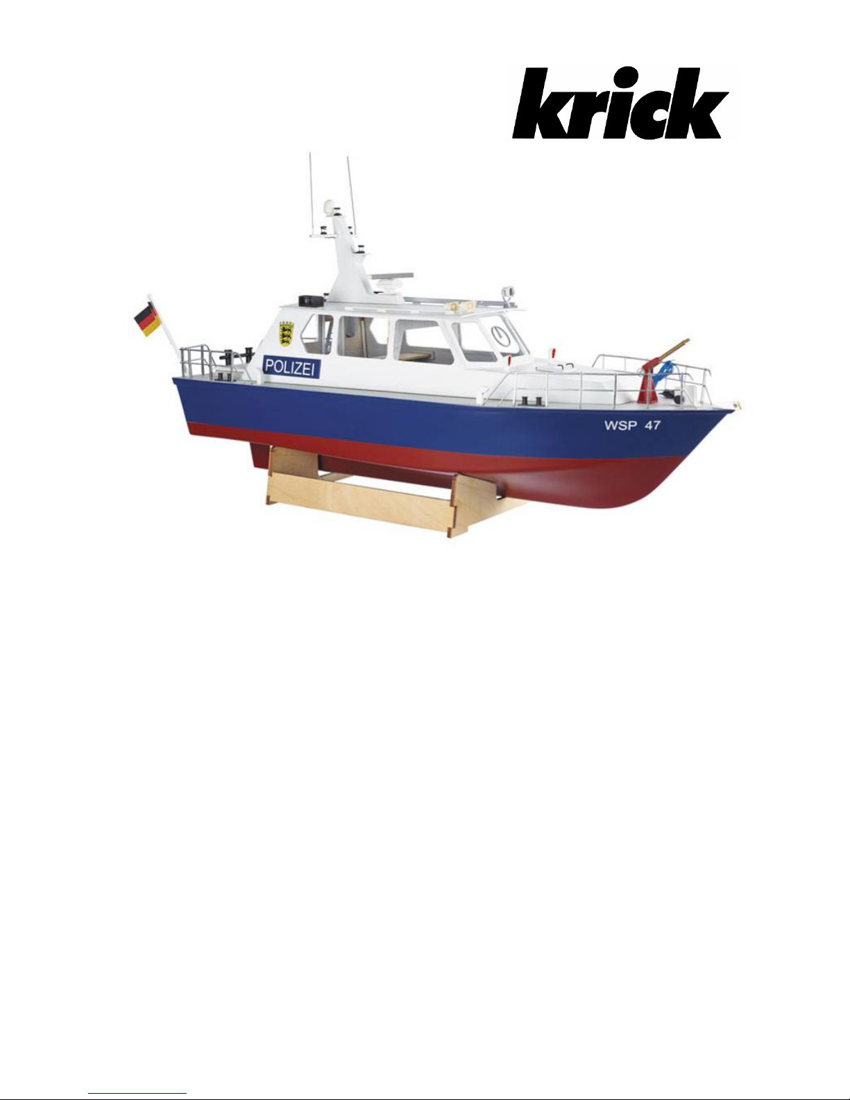
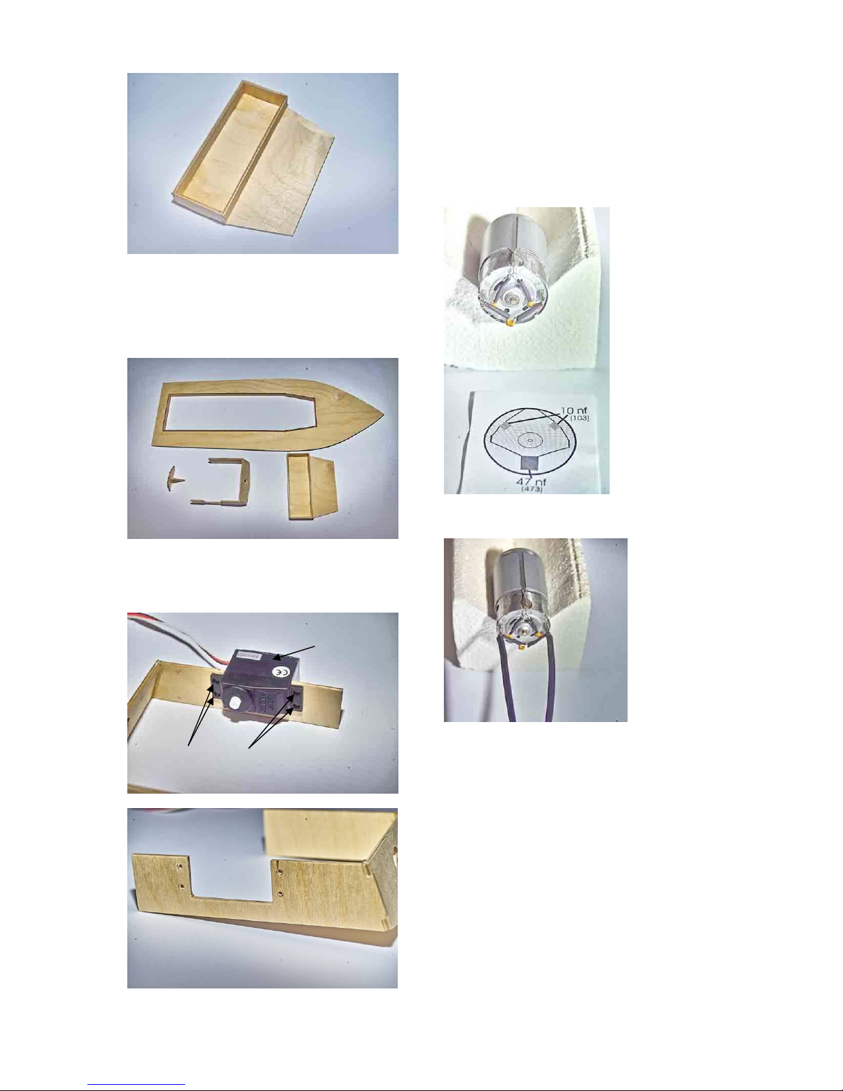
1. Boat stand
First build the boat stand with parts 2, 3 and 4.
After the glue is dry carefully sand and varnish
the stand several times. As you will later place
your wet model on the stand, it is important to
have this water resistant. To protect the model
you can use some pieces of foam tape on the
stand parts which will come in contact with the
hull.
2. Hull
Mark the positions of the rudder tube and of
the prop shaft on the hull (1). First measure the
centre line of the hull and mark. Then mark the
rudder tube position 35 mm from the stern of
the hull. Mark the position of the prop shaft 15
mm down from keel end.
Now drill the holes for prop shaft and rudder
tube.
First use a small drill of about 2 – 3 mm and
then enlarge to the correct size – rudder tube 4
mm and prop shaft tube 6 mm. You can do this
best with a round file to stop the hull from splitting.
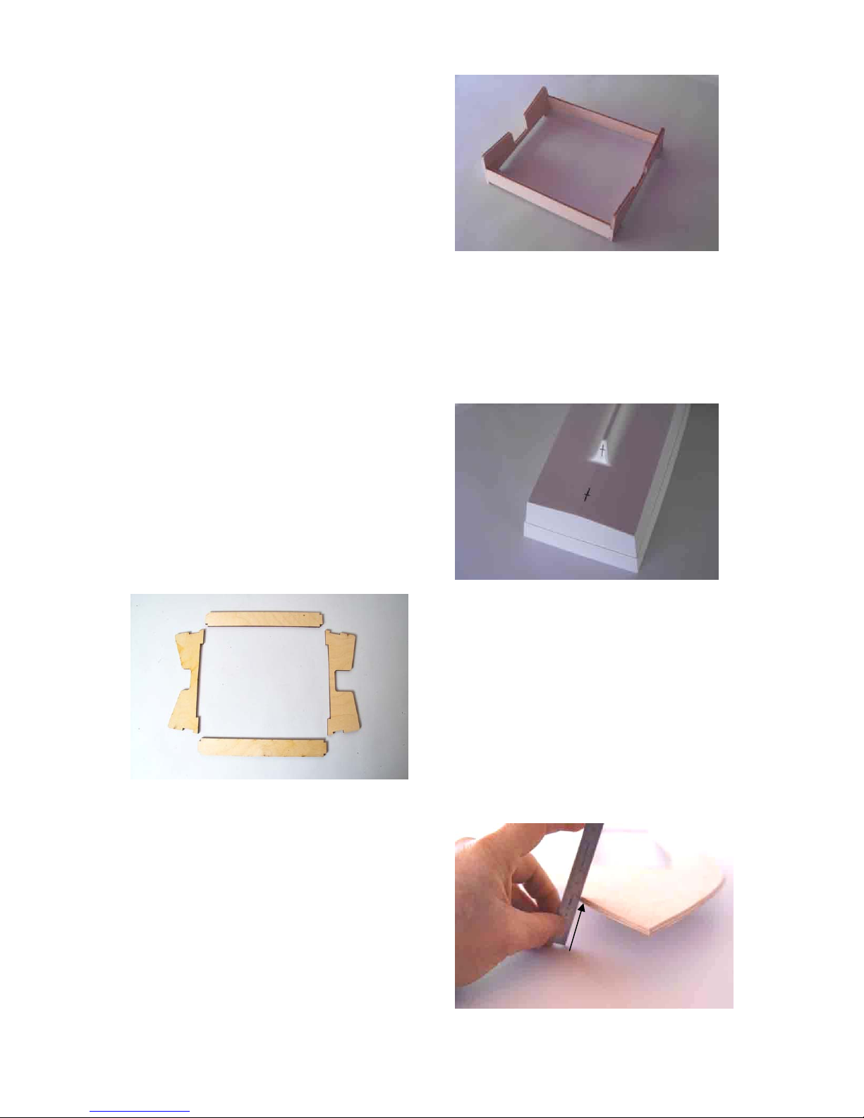
3. Deck
Now fit the deck to the inside of the hull (5). At
the area of the bow it is necessary to chamfer
the deck so it is a snug fit and sits in the hull
without any pressure being applied.
2
3
4
4
1
5
chamfer in the front
area
Stand Juli 2014 Seite 3 © Krick Modelltechnik Knittlingen
Now place the deck into the hull and mark a
line on the sides 2 to 3 mm over deck level.
Cut the hull down only until to this line with a
sharp knife or strong scissors.
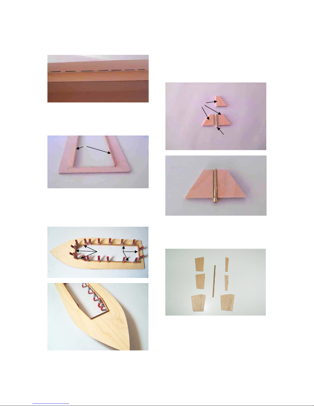
Now place strips (6 to 9) on the underside of
the deck around the inner cut out. Place a
weight on the deck until the glue is dry so the
deck cannot twist.
Now the coaming strips (10 to 13) have to be
glued vertical to the strips so that they are flush
on the underside and protruding on the upper
side. The superstructure will sit over this so
that no water can ingress the hull.
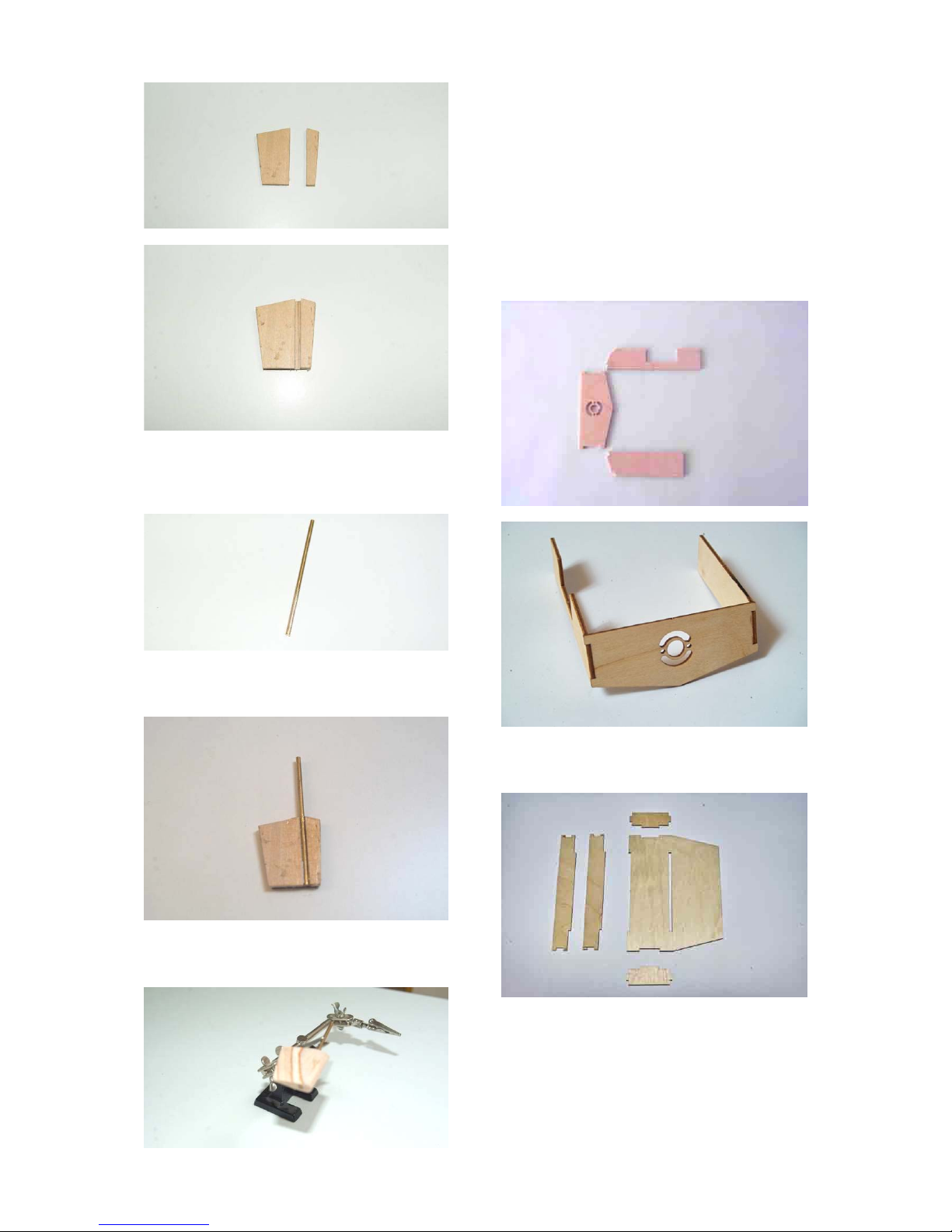
4. Rudder Tube
Glue the rudder tube (14 ) to the 2 supports
(15). Use medium or thick super glue or UHU
plus acrylit glue for this. Place the parts onto a
flat surface. Once dry place the assembly into
the hull along with the third support. Glue this
support to the rudder tube, but do not yet glue
into the hull.
5. Rudder
Make the rudder from parts 160 – 163. First
glue parts 162 and 161 to each other.
5
1
5
6
5
5
10 to 13
15
14
162 161
163
160
Stand Juli 2014 Seite 4 © Krick Modelltechnik Knittlingen
Then glue these inner parts onto one outer
side (160) that a gap remains for the rudder
shaft.
Roughen well the rudder shaft on the area,
which will be glued into the rudder.
Now glue in the rudder shaft with Uhu Acrylit
and the second outer plate (160) on top.
Now make a profile on the rudder, sharp at the
end and round at the front.
6. Motor Mount
Make the motor mount / Servo tray assembly
from parts 16-17 and 18 and glue. You will find
on the laser sheets two different motor mounts.
First compare with the motor, which motor
mount is the correct one for your motor.
For 400 motors there are parts on sheet 2.For
500/600 motors on sheet 3.
Now make the battery and receiver tray with
parts 19, 20 and 21.
16
17
18
19
20 20
21
21
Stand Juli 2014 Seite 5 © Krick Modelltechnik Knittlingen
All parts for the inside of the hull should be
ready now. Please varnish them 2 to 3 times
and sand between each application so that
they are water proofed. Also the deck should
be varnished on the underside.
Place the Servo temporarily into the tray and
drill the holes with 1.5 mm drill for the Servo
screws.
7. Preparation of the Motor
Solder on the motor the suppression capacitors 103 (10nf) to the connections and to the
motor housing as shown. Sand before soldering, to ensure a good connection for the solder.
Then solder the third capacitor 473 (47 nf)
between the two motor connections. Place
insulation tube on the ends before soldering.
Now solder motor wires to the connections.
After that you can assemble the motor to the
motor frame.
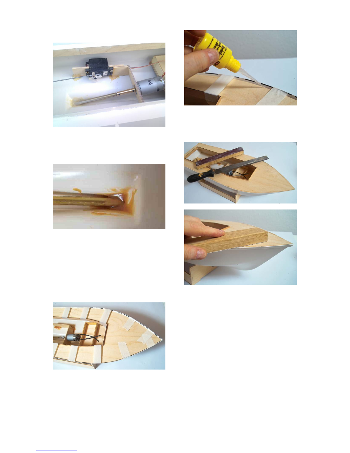
8. Fitting out the Hull
Push the prop shaft through the hole in the hull
and fit the motor on the motor mount. Now
attach the brass coupling between Motor and
prop shaft with grub screws M3. Please check
that there is a gap of about 1 mm between
motor housing and coupling.
Now align the motor together with motor
mount, prop shaft and tube inside the hull. The
whole setup should be placed in the centred of
the hull so that the tube of the prop shaft is
protruding 25 mm out of the hull.
Before proceeding double check that the assembly is placed in the centre of the hull.
Servo
Drill
Stand Juli 2014 Seite 6 © Krick Modelltechnik Knittlingen
Now fix the tube and the motor mount with
UHU Plus Acrylit inside the hull and fill the end
of the hull around the shaft with glue so that it
is water tight.
After the glue is set, you can also fix the rudder
shaft and the battery platform in the same way.
9. Gluing the Deck
Now all interior is placed correctly inside the
hull. So it is time to fix the deck permanently on
the hull. Fix the deck with adhesive tape to the
hull in a way, that the side walls of the hull are
pressed equally to the deck without getting
waves.
Fix the deck at several points with thin superglue. After that you can fix the deck complete
with medium superglue You can use an activator spray to shorten the drying process.
After the glue is dry you should sand the overlying border of the hull down to deck level. If
gaps appear, you can fill them with a wood
filler.
Stand Juli 2014 Seite 7 © Krick Modelltechnik Knittlingen
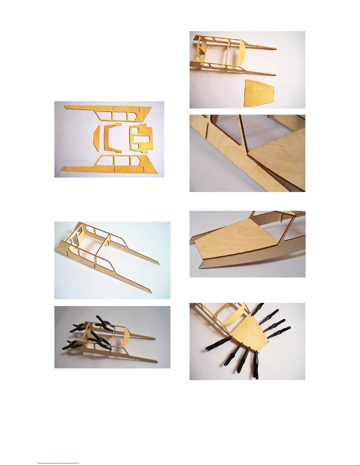
II SUPERSTRUCTURE
1. Cabin
For the first step of building the superstructure
you will need parts 32, 33, 34 und 40.
Now draw the outline of the windows to the
glazing material of PVC (100). Make them
slightly oversize to allow for gluing to the
frames.
Dry fit the parts first. If necessary sand the
slots or tenons for a perfect fit. Now first glue
the side walls to the frame and back wall.
When the gluing points are dry you can glue
the bar (40) in place.
2. Cabin Roof Front
Now place the front roof (35) with its cut out
corners between the two side walls and glue
only at the cut outs.
Fix the roof at its cut outs with superglue.
When the glue is dry, bend the side to the
curve of the roof and fix with superglue.
When the glue is dry, do the same on the other
side. After this apply glue from inside, and then
fix with clamps.
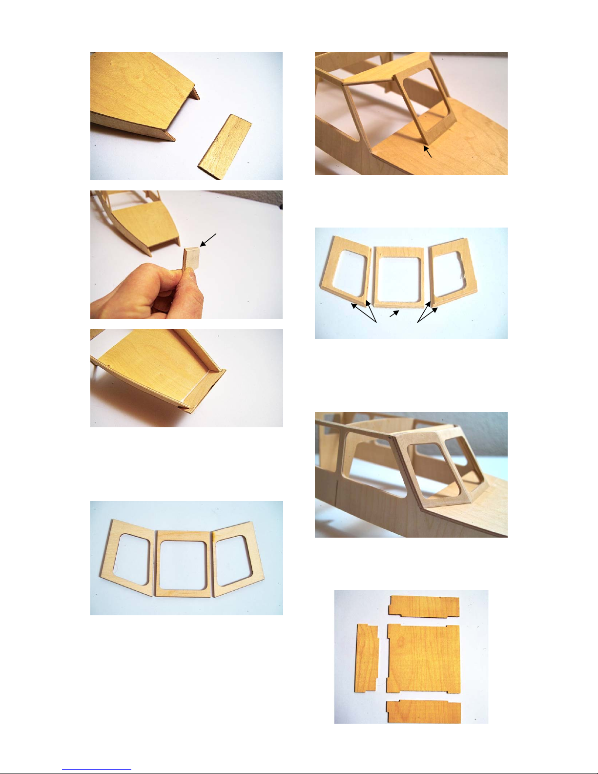
Now fit the front part (37) to the superstructure.
The upper edge needs to be sanded at an
angle to fit correctly.
32
34
33
32
40
35
Stand Juli 2014 Seite 8 © Krick Modelltechnik Knittlingen
Now sand the flush the overlaying ends.
3. Front Windows
In the next step the front windows 38 and 39
will be fitted..
First bevel the lower edge of the centre part
about 45 degrees.
The front windows at the side have to be bevelled at the lower edge and at the edge to the
centre window.
In the next step you have to sand the contour
of the main roof on top of the front windows in
the same way as the contours of the frame and
back wall. Then sand the side edges flush with
the side walls.
4. Cockpit
At this stage you will make the cockpit. For this
you will need parts 49, 50 and 51.
37
sand
to the required angle.
38 39 39
sand to the
required angle
angular
sand to the
required
angle
49
50
51
50
 Loading...