

Krick 20310 Instructions Manual

SUBMARINE Type VII b
Technical data of the original of the model:
Scale 1:1 1:60
Length 66.5 m 1120 mm
Width 6.2 m 125 mm
Height (keel to top edge of tower) 9.5 m 170 mm
Building Instructions
Congratulations on your purchase of this construction set. The submarine type VII was probably one of
the most built submarines in the world. In its time it set the standard and became very successful. We
hope that you will have a lot of fun building this model - either as a display version or a fully functional
diving model.
With this construction set you can either build a pure display model without any additional kit or a fully
functional diving model using the dive and drive set (Order no. 10311) which includes a flood tank and
pump. The diving rudders fore and aft were enlarged somewhat for the functional version in
comparison with the scale. Also, some covers on the hull of the diving model were designed to be
removable, which, on the standard version, do not, of course, have to be cut open. These instructions
apply to both models - any differences are clearly described.
You also need the following material to build the standard model:
- ABS special adhesive, order no. 80478
- Fast adhesive “Ruck-Zuck”, order no. 80492
- UHU “plus endfest” 300 adhesive, order no. 45640
- UHU “plus Acrylit”, order no. 48315
- UHU “allplast”, order no. 48410
- Spray lacquer, colours light grey and dark grey
- Small pots of paint (Humbrol or similar), black
- Lead ballast strips, 60 g, order no. 60107 (2 off)
We recommend the following tools for the construction:
- Sharp and strong model building knife, order no. 416002
- Replacement blades for the knife, order no. 420019
- Drill bits, sizes 1 mm, 1.5 mm, 2 mm, 3 mm, 4 mm, 5 mm and possibly 7 mm
- Metal ruler
- Sanding block and sanding paper, various grades
- Round and flat files
Page 1 © Klaus Krick Modelltechnik Knittlingen August 2002

The Material:
The plastic used in this model set is 95% pure, impact-resistant ABS plastic. This material has a very
long life and will not become porous quickly like some other plastics. We have been using this material
for over 20 years in our production and, with the outside of the model lacquered, had the best results
with it. The best adhesive for this material is the Krick ABS special adhesive (order no. 80478). This
adhesive dissolves the ABS very slightly and virtually welds the components together.
However, due to its many small details, the deck could not be manufactured from ABS. We have used
polystyrene plastics instead.
Important: When gluing, please note that polystyrene (i.e. the deck) cannot be glued using the
ABS adhesive. The adhesive will not solve this material. In order to connect ABS with polystyrene,
“UHU allplast” or an epoxy adhesive should be used. Please make absolutely sure that you use this.
Cutting out the ABS Components:
In order to find the correct cutting edge, please look very closely at the drawings in these instructions.
Black-and-white triangular arrows show exactly from which side any edge should be cut with the knife.
The remainder is always shown as hatched on the drawing. Carefully score the edge several times,
then carefully break off the components. If large residues remain around the component, first cut off
the steep walls of the residues before getting to the actual component. Take particular care on
corners. It is better to score several times until the material is almost cut through otherwise cracks
could develop into the components which are uncontrollable because plastic do es not have a structure
or directional fibres. Keep the remaining scrap bits, in particular the long straight strips of the hull
components. This is not waste material, some components are actually made from the strips of this
residue.
The Dive and Drive Kit (Order no. 20311):
This kit contains all the parts you need to build a functional diving model, except the radio remote
control, drive control and batteries. Some parts are also found in the basic kit which are put there
simply because it is easier to pack them there. You can quite easily tell which parts are in which kit by
the markings in the item list at the end of these instructions.
Besides the drive and dive kit, you also need the following items for the operation with remote control:
- Remote radio control, minimum 4 channels
- Drive control 12 V, 30 Amp, forward-reverse
- Drive control or forward-reverse switch to operate the pump
- Battery pack of 10 NiCd cells (recommended: min. 1300 mAh). Two battery packs of 2 times 5 cells,
or 4 and 6 cells have proven to be better for easier installation and removal.
Step 1
Cut out the hull halves (1 & 2) from the outside, as shown. First you cut off the large side walls of the
remaining material in order to obtain pieces that are easier to handle. Then score from the outside of
the hull in the edge of the hull component as per the drawing and carefully bend off the remaining
material.
Page 2 © Klaus Krick Modelltechnik Knittlingen August 2002

Using first fine and then coarse sanding paper, sand the flood apertures that are raised from the inside
and the details. Sand down to the wall. When building the display models, we also recommend
sanding the apertures, but unlike in the powered model where they are to remain open, they are then
closed again from the rear using a black lacquered component. This, in our view, makes the apertures
look tidier rather than just leaving them closed and only painting them over.
Using fine sandpaper that is glued to a larger level plate, sand the edges absolutely level so that the
two hull halves fit precisely when glued together. Use this technique on all cut-out components.
Bend some strips of 12 x 1.5 mm ABS so as to follow the contours of the hull radius. Cut these into 40
pieces of 25 mm length each (3). They will be glued to the interior of the lower hull half.
Tip! To bend the plastic strips, pull them over the edge of the table of your workbench until they roll
up. Repeat this until the correct radius is achieved.
Cut 9 strips of 50 x 10 mm (4). They are used to connect the upper side of the hull - 2 pieces in the
area of the bow before the removable section, 5 in the central removable part. Leave a gap of at least
37 mm in the area of the cut of the removable part (see drawing).
Page 3 © Klaus Krick Modelltechnik Knittlingen August 2002
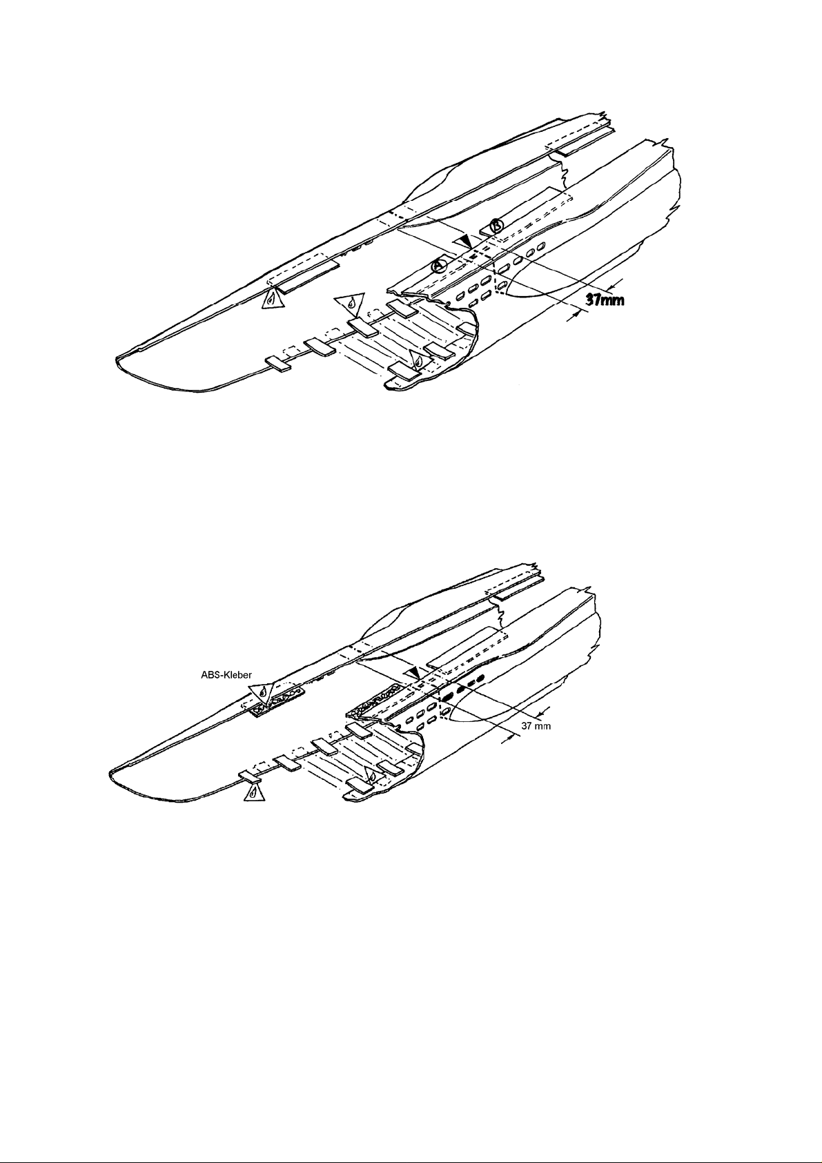
Start by gluing 20 bent strips (3) in the area of the floor onto each hull half at a distance of ca. 35 mm
between each component, so that they interlock with each other.
Glue two strips of 10 mm (4) into the area of the bow and then a further 5 in the central area as shown.
Make sure that there remains a gap of 37 mm on the cut line for the form pieces (7).
Put together the hull halves without glue to check that the connecting strips do not interfere with each
other. Once they fit well, put some ABS adhesive on all the connections and also along the hull edges
except for the central piece. Hold these pieces together with adhesive tape and let the adhesive dry
overnight.
Once dry, sand down the overlapping glue with wet sanding paper until the connecting edge i s
smooth. Any gaps can now be filled with plastic putty. You can also make your own putty in a small
jam jar with ABS adhesive and ABS chippings. However, it will take some time until the plastic has
dissolved in the glue enough so that it can be used.
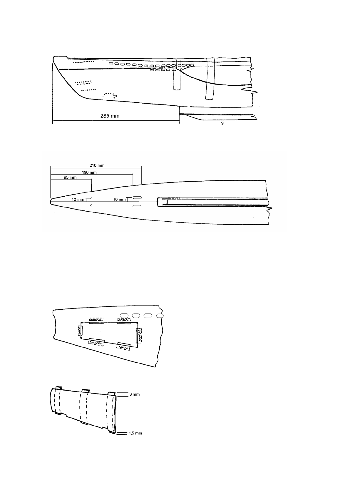
Draw the cutting line for the removable central part with a pencil following the drawing. Four flood
apertures at the bow and 6 apertures at the stern remain in the central part. Score and then cut out
only the left (backboard) side.
Cut out the internal filler pieces for the bow (5) and the stern (6) as shown. Using a suitable rod that is
fitted with some double-sided adhesive tape, the filler pieces, already glued, can then be inserted and
pressed in as per the drawing.
Page 4 © Klaus Krick Modelltechnik Knittlingen August 2002

Now put some ABS glue on the 5 linking pieces of the central part and re-insert the backboard central
part. Let the adhesive dry.
Once dry, score and cut the right (starboard) central part so that the whole section can be removed.
Fasten 4 small link pieces (small plates) made from scrap material, as per the drawing, to the central
part so that it sits flush and hooks up in the hull when closing the cover.
Now apply a bead of glue to all joints from the inside in order to stabilise the hull and central part.
Cut From
Outside
Cut From
Inside
Now cut out the 4 cover fastening braces. For this, first cut along the wavy lines from the inside and
then the cross lines from the outside. The parts are marked with dots from 1 to 4.
First fit the braces without glue into the hull. The part with one dot is aft backboard, with 2 dots is fore
backboard, 3 dots is aft starboard and 4 dots is fore starboard. Once the parts cleanly fit together, glue
them in ensuring that the glue does not touch the central part.
Page 5 © Klaus Krick Modelltechnik Knittlingen August 2002

Fixing with nuts and bolts: Set the central part back on the hull and hold it with adhesive tape. Drill 4
holes of 3 mm diameter through the central part into the braces. Remove the central part again.
Push screw (104) through the hole in the hull and tighten the cover-fastening nut (8) on the inside and
check that the face of the nut is touching the braces well. Then seal the nut using “UHU plus” without
getting any adhesive onto the thread. Whilst doing this, firmly hold the nut with the screw until the glue
has set. Let everything dry before removing the screw again.
Cut the keel out of the deep draw component from the inside. Make sure it fits well to the underside of
the hull. The pointed end is facing the bow. Do not glue the keel to the hull yet. Fill the keel with rolled
lead or lead balls (our order no. 60108) until it has a weight of 350 to 400 gramms. Rolled lead can be
glued in with some epoxy adhesive. Lead balls can be mixed with some epoxy adhesive and then
filled into the keel. Please note that epoxy adhesive becomes warm. Heat develops particularly when
the adhesive layer is too thick which could deform and destroy your keel. Be careful not to let any lead
be proud of the edge so that the keel can later be attached under the hull without problems. Finally,
there should be no air left in the keel as it could cause uplift.
Re-fasten the central part to the hull and place it upside down. Draw the dimensions shown on the hull
and glue the keel along the centre line to the hull. Let everything dry well. The edge of the facing area
Page 6 © Klaus Krick Modelltechnik Knittlingen August 2002
of the keel on the hull can then be sanded and filled to a chamfer.
.
Now measure and mark all other parts cut out from the build plan and the following drawings and mark
these dimensions on the hull.
Use a straight edge for attachment and place it vertically at the stern. For drilling the two holes for the
rudder tubes first use a 2mm drill bit, then open it up to 4mm. For the space for the stern tubes, we
also recommend starting off drilling the end point with a small drill bit and gradually opening it up to
7mm and filing it.
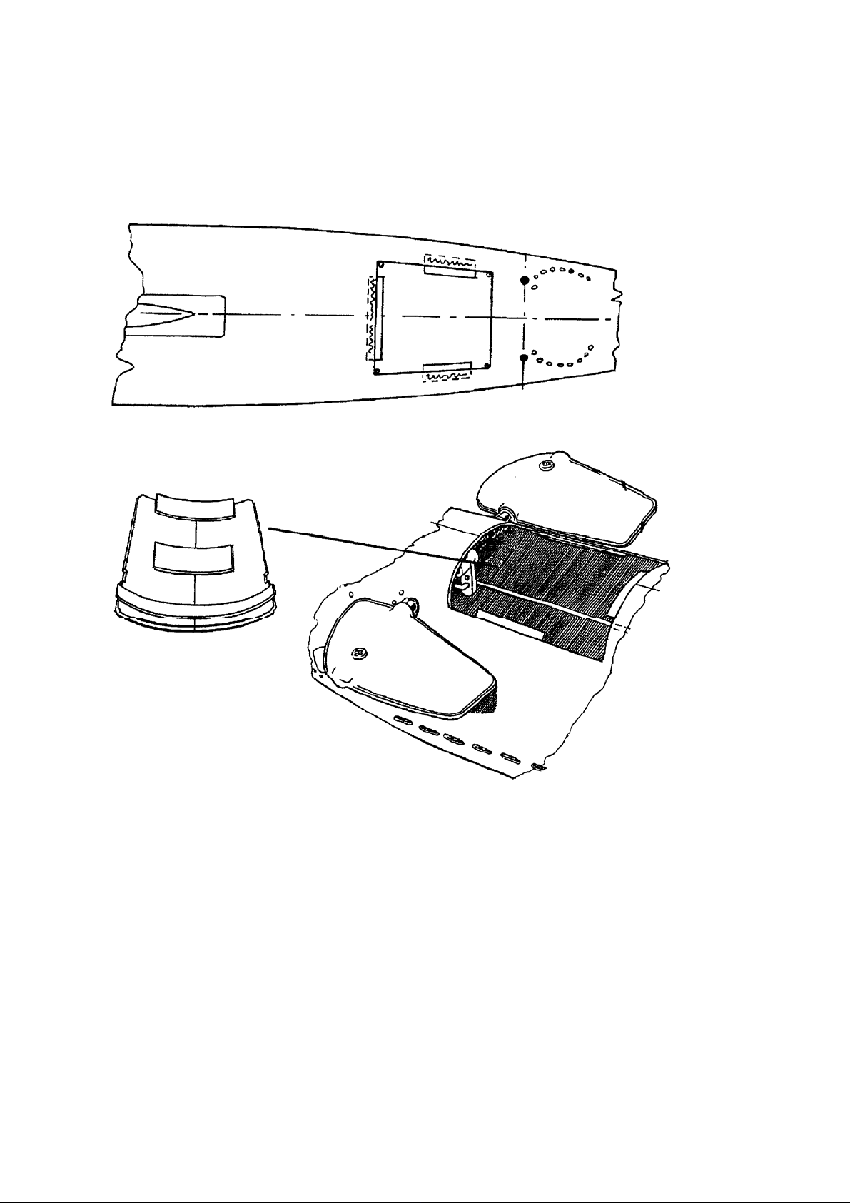
Now draw the lateral hatch for the rudder unit on the hull’s starboard side, as per the build plan. If you
are left-handed, it would be sensible to attach this hatch on the backboard side. Drill into the corners of
the hatch with a 1.5mm drill, link the bore holes with a ruler and score several times with a knife along
this line until the plastic is cut through. File the cut edges smooth and, using the scrap material, attach
6 small pieces around the edge on the inside of the hull so that the hatch cannot fall in.
Cut out 3 strips for the cover which you then glue vertically to the inside of the cover. The cover should
then be hooked in with its upper edge into the hull and slot into the lower edge by lifting it up and over.
Page 7 © Klaus Krick Modelltechnik Knittlingen August 2002
Now you can cut out the hatch for the front fins in the floor of the hull. The measurements for this
please take out of the building plan or make the size yourself that you can fit your hand in to make
adjustments. Cut it out along the fat line and lay it over the hull floor so that the two fat black dots lie
exactly on the large markings for the fin shaft. Then clearly mark with a drill the corner points of the
hatch and drill these through with a 1.5mm bit. Then link these corner holes, as with the stern hatch,
and cut them out the same way. As with the stern hatch, apply scrap pieces on the inside of the hull to
the edge of the hatch so that the hatch lid cannot fall in.
Then you apply scrap pieces to the lid, as per the drawings below, so that it can be hooked up and
clamped in like the stern hatch.
The fins and connections will be fitted later.
Assembly of Pressure Tank
Before the two half shells of the pressure tank are glued together, they need some preparatory work
which is a lot easier when done beforehand.
Preparation of Lower Shell (11)
First cut off the rough edge of the lower shell. Make sure you know which are the front and the rear of
this part. The end with the slightly rounded floor is the rear, the end with the wedge-shaped bulge is
the front. Now the holes for both stern tubes are marked and drilled out to 7mm diameter. For this, first
of all mark a vertical centre line on the outside of the rear wall. Then draw a line parallel to and 5 mm
from the upper adhesive edge and mark the centre points of your holes on this parallel line at a
distance of 18mm from the central vertical line. Start drilling with a 2mm bit and increase the hole
gradually whilst ensuring that the central point of the hole is maintained. [“Unterschale” =lower shell]
Page 8 © Klaus Krick Modelltechnik Knittlingen August 2002
 Loading...