


Fiber Moving Equipment
OWNERS MANUAL
MODEL #5200-P
50 YEARS OF QUALITY AND SERVICE
KRENDL MACHINE COMPANY • 1201 SPENCERVILLE AVE
DELPHOS, OHIO 45833 • TELEPHONE 419-692-3060 • FAX 419-695-9301
E - MAIL: krendl@krendlmachine.com • WEB SITE: www.krendlmachine.com

MODEL #5200-P
CONGRATULATIONS ON YOUR PURCHASE OF KRENDL EQUIPMENT
THIS IS YOUR
MODEL #5200-P OWNER'S MANUAL
FOR ASSURED SAFETY AND CONFIDENCE, PLEASE READ THIS
MANUAL CAREFULLY BEFORE INSTALLING AND OPERATING YOUR
MACHINE.
KRENDL E-MAIL ADDRESS IS: krendl@krendlmachine.com
KRENDL WEB SITE IS: www.krendlmachine.com

MODEL #5200-P
T able of Contents
INTRODUCTION . . . . . . . . . . . . . . . . . . . . . . . . . . . . . . . . 1
UNPACKING & INSPECTING EQUIPMENT . . . . . . . . . . . . 2
GENERAL SAFETY INFORMATION . . . . . . . . . . . . . . . . . 2-5
DECALS . . . . . . . . . . . . . . . . . . . . . . . . . . . . . . . . . . . . . 5-7
WARRANTY . . . . . . . . . . . . . . . . . . . . . . . . . . . . . . . . . . . . 8
RETURNED GOODS PROCEDURE . . . . . . . . . . . . . . . . . . 9
SPECIFICATIONS . . . . . . . . . . . . . . . . . . . . . . . . . . . . . . . . 9
BASIC COMPONENTS . . . . . . . . . . . . . . . . . . . . . . . . . . .
INSTALLATION . . . . . . . . . . . . . . . . . . . . . . . . . . . . . . . . 11-13
OPERATING INSTRUCTIONS . . . . . . . . . . . . . . . . . . . . 14-17
GENERAL MAINTENANCE . . . . . . . . . . . . . . . . . . . . . . 18-21
ELECTRICAL SYSTEM . . . . . . . . . . . . . . . . . . . . . . . . . . . 22
TROUBLESHOOTING . . . . . . . . . . . . . . . . . . . . . . . . . . 23-24
SPARE PARTS LIST . . . . . . . . . . . . . . . . . . . . . . . . . . . . . 24
PARTS LIST . . . . . . . . . . . . . . . . . . . . . . . . . . . . . . . . . 25-31
GLOSSARY . . . . . . . . . . . . . . . . . . . . . . . . . . . . . . . . . . . 32
. 10
SERVICE RECORD . . . . . . . . . . . . . . . . . . . . . . . . . . . . . 33

MODEL #5200-P
INTRODUCTION
Thank you for purchasing a KRENDL FIBER MOVING MACHINE. With over fifty years experience in manufacturing fiber moving equipment, we have designed and built your machine with the
highest quality parts and workmanship to provide years of reliable service.
This manual has been prepared to help you obtain the maximum efficiency and service from your
Krendl equipment. This machine is designed to blow cellulose, fiberglass and rockwool into attics. Our
primary objective is to build equipment which will provide complete satisfaction so that you may
confidently recommend Krendl to others.
We do not manufacture or sell fiber. Our interest lies only in the proper performance of the
equipment we manufacture. The fiber material manufacturer’s instructions prevail when it comes to
applying their product, since they guarantee the final results.
This manual contains important information regarding the safe assembly and operation of your
machine. We urge you to read it carefully and THOROUGHLY before putting your machine to work. If
your questions are not answered in this manual, please contact us. We want you to be able to operate
this equipment safely and confidently.
Upon receipt of this machine, check it carefully for any shipping damage. If there is damage or if
any of the parts are missing, notify the delivery trucking company immediately and file a claim for
damages, saving all packaging materials for inspection. Our warranty covers manufacturer’s defects
only. If Krendl Machine Company delivered or set up your machine and any parts are missing or
damaged, notify the authorized representative before they leave.
Krendl Machine Company Telephone: 419-692-3060
1201 Spencerville Avenue Fax: 419-695-9301
Delphos, Ohio 45833 U.S.A. E-Mail: krendl@krendlmachine.com
Web Site: www.krendlmachine.com
For your protection in the event of theft or loss, please fill in the information requested for your own
records. This information will be needed for in-warranty repairs. You may also want to attach a copy of
your invoice.
Machine Model No. __________________________________________________________________
Machine Serial No. __________________________________________________________________
Engine Manufacturer ________________________________________________________________
Engine Model No. , Serial No. _________________________________________________________
Blower Manufacturer ________________________________________________________________
Blower Model No., Serial No. __________________________________________________________
Blower Clutch Manufacturer __________________________________________________________
Blower Clutch Model No., Serial No. ____________________________________________________
Airlock Clutch Manufacturer ___________________________________________________________
Airlock Clutch Model No., Serial No. _____________________________________________________
Rev. Date: 12/14/10 Page 1

MODEL #5200-P
UNP ACKING AND INSPECTING EQUIPMENT
RECEIVING YOUR MODEL #5200-P KRENDL MACHINE:
Immediately check the condition of your Model #5200-P machine when it is received. It
should be received in the same condition that it was shipped to you. If there are any visible problems with your machine or any other items in the shipment, it is imperative that you place any
claim with the delivery carrier. Please save all packaging materials for inspection. The delivery
carrier should also contact our office before leaving the premises to notify us of a claim. The ownership
to your machine and all other items in the shipment were transferred to your name as soon as the
shipment left our premises, thus it is your responsibility to contact us with any claims. Contact the
truck line to arrange for an independent inspector to come out to inspect the damage and to prepare
the inspection report. It is imperative that this inspection is done prior to unpacking or using any of the
equipment. Please contact us for assistance or with any questions you may have regarding the claim
process.
UNPACKING:
Handle all cartons with care to avoid damage from dropping or bumping. Completely remove
machine from the packaging and from any shipping pallet or skid to which it might be attached. In
addition, completely remove all shipping materials from inside the machine. Check that all parts are
included as stated on the list below .
ACCESSORIES INCLUDED:
• 150’ REMOTE CONTROL CORD
• MULTIMETER
• SPANNER WRENCH FOR BELT TENSIONERS
• #50 CHAIN MASTER LINK
• SECTION OF CHAIN FOR CHANGING SHREDDER DIRECTION
• 5/16 ALLEN WRENCH FOR ADJUSTMENT OF CHAIN IDLERS
• OWNERS MANUAL
GENERAL SAFETY INFORMATION
Important: Read all instructions before operating this equipment. This equipment can be poten-
tially dangerous and must be used in strict accordance with instructions.
Disclaimer Notice: The manufacturer will not be legally responsible for any injury or damage
resulting from the improper use of this equipment or the failure to follow instructions.
Unpacking
Handle cartons with care to avoid damage from dropping or bumping. Completely remove the
machine from the packaging and from any shipping pallet or skid to which it may be attached. In
addition, completely remove all shipping materials from the inside of the machine.
Important: Please recheck inside the hopper for any loose items or damaged equipment.
Injury may occur when equipment is started with foreign material in the hopper .
Rev. Date: 12/14/10 Page 2

MODEL #5200-P
General Safety
1. Read this manual carefully and become familiar with your machine. It is important to know it’s
applications, limitations, and any hazards involved prior to operating the machine.
2. This machine was designed and manufactured for blowing cellulose, fiberglass and
rockwool. Do not attempt to modify the unit or use it for any application it was not designed
for. If you have any questions about your intended use or the machine’s suitability, ask your
dealer/distributor or consult the factory . The manufacturers could not possibly anticipate every
circumstance that might involve a hazard. For that reason, warnings in the manual and
warning tags or decals affixed to the unit, are not all-inclusive. If you intend to handle, operate, or
service the unit by a procedure or a method not specifically recommended by the manufacturer,
first make sure that such a procedure or method will not render this equipment unsafe or pose
a threat to you and others.
3. Do not disable any of the safety features on the equipment. These features are for your
protection and safety .
4. Read and obey all safety and operating instructions in the manual and on the machine.
5. Equipment is to be operated and/or maintenanced by TRAINED & QUALIFIED personnel ONL Y!!
6. BEFORE PERFORMING ANY MAINTENANCE ON THE MACHINE, YOU MUST FIRST:
#1 TURN THE DISCONNECT SWITCH TO THE “OFF” POSITION
#2 DISENGAGE PTO AND TURN THE TRUCK OFF
#3 TURN THE IGNITION TO THE “OFF” POSITION AND REMOVE KEY
7. Do not operate the machine without all guards and safety equipment installed in the proper
location and in working order. Always follow the proper shut down procedures outlined in Item 6
when guards are removed from the machine or when compartment or electrical control doors
need to be opened.
8. If a malfunction occurs while running the machine, turn it off immediately, follow the directions
under item 6 and correct the problem prior to restarting the machine.
9. Keep body and all clothing away from rotating equipment. Rotating shafts can be dangerous.
10. Always wear proper safety equipment when operating the machine. This includes steel toed
shoes, safety glasses and a respirator.
11. Under no circumstances should your hand, a stick or a broom be used to force material down
into the hopper. The machine is a self feeding design and requires no outside assistance.
12. Stand on the floor, not a platform while operating the machine. The operator may lose balance
and fall while loading bags of material.
All Model #5200 Machines are factory equipped with side, front, and main drive belt guards. The top
of the machine is not guarded since it poses no safety threat for normal insulation blowing operations
when mounted as shown in the installation guide. The machine is designed to be mounted in the van
body of the contractor’s truck and the rear of the machine against the wall of the van body.
Always turn the main power switch (located on the electrical box) to off and unplug the remote cord
from the receptacle for any type of machine maintenance or adjustments. An additional safety feature
is the ability to adjust the material slide gate from the outside of the machine. Rotate the adjustment
handle clockwise to open the slide to the desired setting, no entrance into the machine is required.
All safety features are incorporated into the machine to protect everyone from serious
injury. Operate your machine according to the outlined instructions in the manual with all
guards in place and securely latched. Operation with any guards removed can result in injury
to or loss of fingers, hands, arms, toes, feet, legs, hair, and even your eyes.
Rev. Date: 12/14/10 Page 3

MODEL #5200-P
Electrical Safety
• The National Electric Code (NEC) in the United States and many international electrical
codes require frame and external electrically conductive parts of this machine to be properly
connected to an approved earth ground. Local electrical codes may also require proper
grounding of machine. Consult with local electricians for grounding requirements in your area.
• Never handle any kind of electrical cord or device while standing in water, while barefoot or while
hands or feet are wet. Dangerous electrical shock will result.
• Use a ground fault circuit interrupter (GFCI) in any damp or highly conductive area. (metal decking
or steel work)
• Reference NFPA 79, 70E, or OSHA safe work practices when preforming energized work procedures.
Safety/Caution
• Be Safe - Keep away from moving parts.
• Be Safe - Make sure all guards and hopper extensions are in proper place before operating machine.
Guards and safety devices/switches should not be removed, modified or by-passed.
Hands should never pass between rotating parts.
• Be Safe - Make sure remote control hand pendant switch is in off position before connecting the
power supply to the machine.
• Be Safe - Make sure machine is properly grounded. Protect all electrical supply cords from sharp
objects, moisture, and other potentially hazardous materials. Keep power cords in good
repair. Electrical service must be performed by a qualified electrician.
• Be Safe - Disconnect power supply before inspecting or adjusting unit.
• Be Safe - Consult a qualified technician to answer questions before attempting to operate, or injury
may result.
• Be Safe - Emergency Kill Switch - In case of emergencies, always use red stop button located on
the front of Main Control Panel and on the side of the hopper. It will stop all feeding and
agitation.
• Be Safe - Do not remove motors or lift hopper when unit is connected to power supply.
• Be Safe - Do not operate machine alone.
• Be Safe - Do not leave machine unattended and energized.
• Be Safe - Turn machine off and disconnect electricity before clearing and feeding jam or attempting
to remove any object dropped in the hopper.
• Be Safe - Keep hands, loose clothing, jewelry and hair away from agitators, gears, chains and other
moving parts.
• Be Safe - Use proper lifting when moving fibers and loading machine.
• Be Safe - Keep work area clear of debris.
• Be Safe - Wear proper safety equipment, including protective gear, such as respirators, eye and ear
protection.
• Be Safe - Violation of the Owner's Manual or safety precautions may void warranty.
Rev. Date: 12/14/10 Page 4

MODEL #5200-P
Make Sure!
• Hopper is empty of foreign objects before starting.
• Adequate electrical power is supplied or damage to unit will result.
• Machine must be on before adding fiber.
• Blower filter is kept clean and in place when blower is on.
• Machine is turned off immediately if hose is plugged, or blower will overheat.
• Blower must be on, when agitators are running, or machine will bind.
• Agitator motor is not run with hopper empty for more than a few minutes, or damage to seals will result.
• Sprockets, chains, belts and pulleys are correctly aligned and tensioned.
• Pieces of bag are not left in the machine as this can bind and stall your machine.
• This machine should only be used with good quality fibers that are dry, undamaged and that meet a
certain industry specification or quality standards.
IF THERE ARE ANY QUESTIONS WITH YOUR KRENDL MACHINE, DO NOT HESITATE TO
CONTACT US AT: 1-800-459-2069
DECALS
General safety information intended to reduce the risk of serious
injury or death
Indicates that the electrical box on the machine is in compliance with UL codes.
Indicates which employee inspected equipment and on what date.
Indicates if blower is off, on, or on with agitator .
Electrical maintenance information and schedule provided here.
Rev. Date: 12/14/10 Page 5

MODEL #5200-P
Keeping the filter clean will result in longer
blower life and better performances.
Manufacturer information is provided here
along with machine model, and serial number.
Emergency stop button for machine.
Rotating parts can be dangerous! You can
snag clothes, skin, hair, hands, etc. This
can cause serious injury or death.
Opens and closes the material feed gate
which in turn controls the production.
Made in the U.S.A.
Read manual before operating machine for assured safety.
T ake caution when handling electrical cords
or electrical shock or death may result.
Machine should be used with these products.
Rev. Date: 12/14/10 Page 6
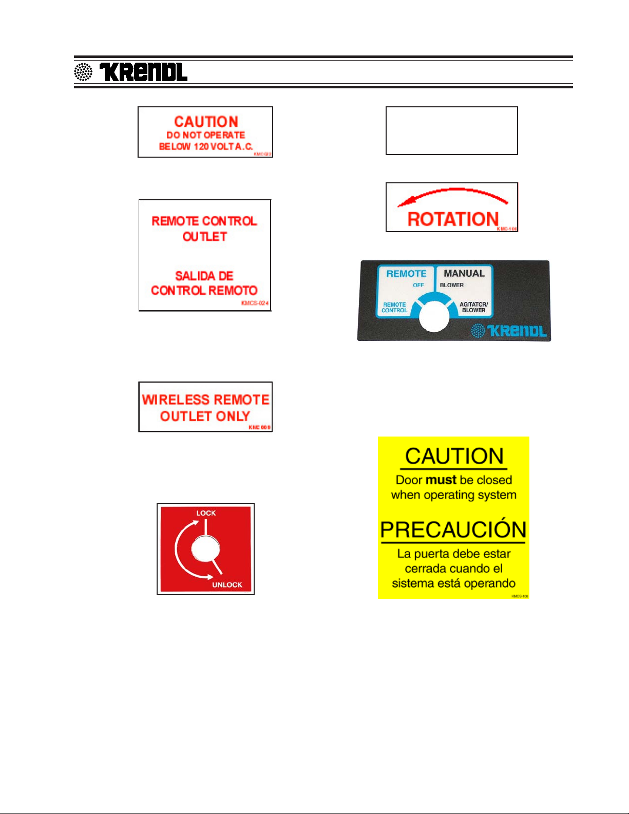
Identifies position of material feed gate.
MODEL #5200-P
KMC-01234
Operating machine at specified voltage will result
in longer machine life and better performance.
Indicates that this outlet is intended for only the
remote control outlet. Each time machine cycle
starts, an audible alarm warns the operator that
the machine is about to come on.
Indicates that this outlet is intended for only the
wireless remote. Each time machine cycle
starts, an audible alarm warns the operator that
the machine is about to come on.
Part number for identification and tracking.
Rotating parts will be moving in this direction.
Identifies if machine is in remote mode, manual
mode, or off position. In manual mode this switch
operates machine. In remote mode the hand
pendant operates machine. Each time machine
cycle starts, an audible alarm warns the operator that the machine is about to come on.
Indicates if the latches on the access door are
locked or unlocked
Rev. Date: 12/14/10 Page 7
Keeping the door closed will keep bystanders
safe from rotating parts.

MODEL #5200-P
WARRANTY :
Krendl Machine Company (Company) warrants to each original purchaser (Buyer) of its
equipment or accessories that such products will be free of manufacturing defects for a period
of 12 months from the date of shipment to the Buyer.
No warranty is made with respect to:
1. Components or accessories manufactured and warranted by others. Warranties for
purchased component parts as supplied from vendor such as engine, electric motor,
blower, gearbox, transmission, etc., if furnished by the manufacturer of the component,
are on file at the Company’s main office and copies will be furnished at request of Buyer.
Component(s), shipping costs prepaid, shall be sent to Company who in turn shall forward
to vendor for evaluation and warranty determination.
2. Any defect caused by repair, alteration and/or adjustment performed by Buyer or
customer/vendor of Buyer without the express written authorization of the Company.
3. The labor costs of replacing parts by parties other than the Company.
4. Any machine that has not been operated and/or maintained in accordance with normal
industry practice and the written recommendations of the Company. (e.g. machine operated with an improperly sized, worn or damaged hose, improper or inattention to preventative maintenance, etc.)
5. The product has been subjected to misuse, negligence or accident or results of any
application or use of the blowing equipment not in accordance with the Company recommendations.
This limited warranty does not cover the free replacement of component parts that become
inoperative due to wear and usage and need to be replaced on a regular basis, including but
not limited to: airlock seal(s), agitator(s), shredder(s), auger(s), fuse(s), switch(es), clutch(es),
hose(s), shaft seal(s), chain(s), belt(s), sprocket(s), pulley(s), bearing(s), cable(s), battery(ies),
filter(s), fan(s), etc.
The Company’s obligation under this warranty is limited to repairing or replacing (at Company
option) any part that is determined by the Company to be suffering from a manufacturing defect.
The Company (at Company option) will provide any required parts and labor to the Buyer. If the
equipment or parts must be returned to the Company for repair, all transportation costs shall
be the Buyer’s responsibility.
THIS LIMITED WARRANTY IS EXPRESSLY IN LIEU OF ANY OTHER GUARANTEES AND / OR
WARRANTIES, ORAL OR WRITTEN, EXPRESSED OR IMPLIED, INCLUDING WITHOUT LIMITATION, THE IMPLIED WARRANTY OF MERCHANTABILITY. NO WARRANTY, EXPRESS OR
IMPLIED, OTHER THAN THE AFORESAID WARRANTY IS MADE OR AUTHORIZED BY COMPANY. COMPANY SHALL NOT BE LIABLE FOR ANY DIRECT, INDIRECT, INCIDENTAL OR
CONSEQUENTIAL DAMAGES TO PROPERTY OR INJURY TO ANY PERSON OR COSTS
ASSOCIATED WITH LOSS OF PRODUCTION RESULTING IN LOSS OF REVENUE, PROFITS
OR LOSS OF EQUIPMENT THROUGH THE USE OF THIS EQUIPMENT.
Note: Special job circumstances incurring costs for specialized repair and next day delivery
of parts will not be reimbursed by the manufacturer unless authorized by factory.
Rev. Date: 12/14/10 Page 8

MODEL #5200-P
RETURNED GOODS PROCEDURE
IF MACHINE WAS NOT PURCHASED DIRECTLY FROM KRENDL MACHINE COMPANY, CONTACT YOUR SUPPLIER / DISTRIBUTOR.
When returning products to Krendl for repair, first obtain a return goods authorization (RGA), at
which time you will be given shipping instructions. The product must be shipped PREPAID:
Krendl Machine Company Telephone: 419-692-3060
1201 Spencerville Ave. Fax: 419-695-9301
Delphos, Ohio 45833 U.S.A. E-mail:krendl@krendlmachine.com
Web Site: www.krendlmachine.com
Once the unit is received, it will be inspected. In-warranty units will be repaired and returned
immediately. An estimate of repair charges will be provided for out-of-warranty units.
SPECIFICATIONS
MODELS: #5200-P
MACHINE: 14” Diameter x 18” Length airlock feeder
electromagnetic clutches on agitator and blower
in line helical gearbox (driving the machine)
HEIGHT: 83.00 inches
LOAD HEIGHT: 59.00 inches
WIDTH (DEPTH): 43.00 inches
LENGTH: 80.00 inches
WEIGHT: 2000 pounds
ELECTRICAL: 12VDC remote control system (6000 watt generator supplying
120VAC to convenience outlets & accessories)
BLOWER VOLUME: 250 CFM
BLOWER PRESSURE: 6.0 PSI maximum
HOSE OUTPUT: 4” diameter
MAXIMUM FEED RATES:
CELLULOSE: 5200 lbs./hr. FIBERGLASS: 2300 lbs./hr.
WARNING:Recommended hose size, type and length must be used to achieve maximum
results. Krendl cannot guarantee performance of the #5200-P machine if hoses are
undersized, worn, damaged, or hoses other than those we recommend are used.
BEFORE YOU RUN THIS MACHINE...PLEASE READ THE REST OF THIS MANUAL!!
Rev. Date: 12/14/10 Page 9

MODEL #5200-P
BASIC COMPONENTS
This is a view of the basic components of your Model #5200-P machine. It shows the location of
each item and gives the function of each. Use this as a guide throughout the manual.
(Illustration 1)
A ) Base Unit - Lower frame unit supporting blower
box, speed reducer, motor, airlock and hopper.
B) Airlock - Traps air and fiber while providing a
metered flow.
C) Shredder System - Increases production and
coverage on all fiber products while reducing
clumps that may exist in various fibers.
D) Slidegate - Meters the amount of fiber dropping
into the airlock by controlling size of airlock
opening.
E) Speed Reducer - Increases output power while
decreasing speed of agitator/airlock drive motor.
F) Agitator - Conditions fiber in the hopper.
G) Hopper - Upper unit of machine holding fiber.
(Illustration 2)
H) Main Control Panel - Connects with main
power, allowing operation of unit at machine or
Remote Cord.
I) Kill Switch - Safety device for immediate stop-
ping of machine.
J) Blower - Provides the air necessary to move
fiber from the airlock.
K) Hydraulic Motor - Provides driving power for
speed reducer, blower, generator, and agitator/
airlock system.
Illustration 1
L) Generator - Provides power to all auxiliary
electrical components.
M) Hopper Extension - Increases overall hopper
capacity.
Rev. Date: 12/14/10 Page 10
Illustration 2

MODEL #5200-P
INSTALLATION
MACHINE DRIVE AND TRUCK SPECIFICATIONS:
Your Model #5200-P Krendl Machine can be mounted in any truck and chassis configuration. We
recommend a minimum chassis rating of 26,000 GVWR. We also recommend a minimum 22 feet van
body . The body should have a full width rear door . The Krendl Model #5200-P Machine can be mounted
anywhere in the truck body . The factory recommended positions are shown in Illustration 3.
TOOLS NEEDED: CUSTOMER SUPPLIED ITEMS:
1/2” Heavy Duty Drill 1/2” Bolts, washers, locknuts for fastening machine
Drill Bits: 9/16” for bolts
Fork Lift (means to lift the machine)
Pry Bars
Basic Wrenches
5” hole saw & 2” hole saw
INSTALLATION INSTRUCTIONS:
1) Place the machine in either of the two locations so that the machine will not be in the way of the
truck’s doors and you are still able to open the hood of the machine.
2) Using illustration 3 as a reference, check under the truck body that the opening will not interfere
with any truck components underneath. If there is any interference with any of the truck parts,
then you will need to adjust the position of the machine to clear the obstruction. The holes for the
blower inlet and machine hold down do not have much room for adjustment. However , the holes
for the hydraulic lines do have room for slight adjustments.
Illustration 3
3) Remove the machine after the holes are located.
Rev. Date: 12/14/10 Page 11

4) Cut the following holes: (Using illustration 4 as reference ONLY)
a. Blower Inlet: 5”
b. Hydraulic Lines: 2”I
MODEL #5200-P
A
B
B
A
Illustration 4
5) Place the machine in the truck lining it up with the holes.
6) Locate and drill 9/16” holes for the four hold down holes located in the bottom of the base flange.
Again, check the underside of the truck body for any obstructions. Use 1/2” bolts and nuts to bolt
the base to the truck floor.
7) Run hydraulic lines to the machine.
8) Attach hydraulic lines to the hydraulic motor. Note: The shaft on the hydraulic motor should be
running counter clockwise. If the motor is running in the wrong direction, disconnect the hydraulic lines and reverse the hook-up.
Hydraulic Lines
Rev. Date: 12/14/10 Page 12

MODEL #5200-P
10) Coming off of the positive terminal on the truck battery, att ach a 15 amp inline circuit breaker.
15 Amp Circuit Breaker
11) Run power from the truck battery to the machines electrical box.
White wire from battery to
block three (3)
Red wire from battery to
power distribution block
12) Attach 4” hose to the filter box inlet so that the hose sticks through the 5” hole cut into the floor of
the truck.
If you need more information, please call your sales agent. Y our Krendl Model #5200-P Machine is
now ready for operation.
Y our Krendl Model #5200-P Machine was checked and thoroughly run before it was shipped but it
is always a good idea to check all belts and chains for proper tension and that all fluid levels are
checked and topped off where required.
Rev. Date: 12/14/10 Page 13

MODEL #5200-P
OPERATING INSTRUCTIONS
Starting Your Krendl Model 5200-P Machine:
1) After installing your Model #5200-P according to the installation instructions, it is now time to start
your machine. Again, check all fluid levels, belt tension, and that all guards are inst alled properly.
2) Attach the blowing hose to the machine and run the hose into the building.
3) Run the remote control cord into the building.
4) Make sure the Control Switch on the remote control cord is in the OFF position. Now, you may plug
in the remote control cord.
5) With truck engine running engage PTO. Make sure PTO is running at proper speed. (With Main
Disconnect ON generator voltmeter should read 120 volts.)
6) Y our machine is now ready for operation.
Note: Agitator motor and blower should only be operated with steady or constant flow of electricity
between 110-120 volts.
Note: When using extension cords, wire gauge size should not be less than input cord on unit and
not exceed 50' in length. (See Voltage Drop Chart Below.)
Ex : A two-wire 20-ampere circuit using 12 AWG with a one-way distance of 25 feet will drop 1.98 volts;
120 volts - 1.98 volts = 118.02 volts as the load voltage.
Rev. Date: 12/14/10 Page 14

MODEL #5200-P
Electrical Operation:
NOTE: PRESS KILL SWITCH TO IMMEDIATELY STOP MACHINE AT ANY TIME!
1. Make sure Kill Switch is out by twisting clockwise/right. (See illustration 5)
2. Turn red Main Disconnect Switch to ON position. (See illustration 5)
3. Set 4-Position Selector Switch to OFF. (See illustration 5)
4. Press green start Button. Machine will not run unless start button is pressed after Kill Switch
is out and red Main Disconnect Switch is on. (See illustration 5)
5. Select operating mode on 4-Position Selector Switch from one of the following options:
Remote: Remote control hand pendant will control machine.
Off: Machine will not run. (overrides remote hand pendant)
Blower: Only the blower will run continuously. (manual control at machine)
Agitator-Feed/Blower: Both the blower and the agitator-feed will run continuously. (manual
control at machine)
Main Control Panel (lid closed)
Illustration 5
Main Control Panel (back)
Illustration 6
Rev. Date: 12/14/10 Page 15

MODEL #5200-P
6. When operating in Remote mode, the 4-Position Selector Switch must be set to Remote
position. (See illustration 5 on page 15.)
7. Remote control hand pendant positions will be selected from the following:
BLOWER-FEED - operates both blower and agitator-feed simultaneously
OFF - (middle position) all functions stop
BLOWER - operates the blower only
8. Use the Auxiliary Outlet on the Main Control Panel for supplying continuous power (while red Main
Disconnect Switch is ON) to accessories.
Stopping Y our Machine:
1) Switch the Remote Switch to “AIR ONLY” and wait until the hose is clear of all material.
2) Turn the Control Switch on the remote control cord to the OFF position.
3) Turn the Main Disconnect Switch to the OFF position.
4) Disengage the PTO.
SAFETY NOTE:
DO NOT FILL THE HOPPER TO CAPACITY AT THE END OF THE DAY. THE MATERIAL
WILL COMPRESS AND CAN CAUSE MACHINE LOCKUP DURING THE NEXT ST ART -UP.
Mechanical Settings:
The controls of your machine contain the blower and slidegate controls to adjust your machine for
each application and type of fiber. (See illustration 7 on page 17.) Blower control (air) and slidegate
(material feed) are adjusted according to:
TYPE OF MATERIAL: Cellulose and fiberglass have different textures and densities that
respond to machine settings.
HOSE: Corrugations or roughness of interior surface, diameter, length and
elevation of hose will also require varying adjustments.
WEATHER CONDITIONS: Temperature and humidity may require day to day adjustment of
machine settings.
Blower Control and Slidegate General Settings:
Blower control can increase or decrease the amount of air in the system, affecting the velocity
(speed) and spread rate (coverage) of fiber. (See illustration 7 on page 17.) The blower control valve
is used for controlling air pressure and amount of air flow.
Opening or closing slidegate (material feed) controls the amount of fiber dropping into the airlock
which changes the production rate (lbs. per hour). (See illustration 7 on page 17.) For calibration
purposes the scale located on the machine indicates how many inches the airlock slidegate is opened.
Rev. Date: 12/14/10 Page 16

MODEL #5200-P
The blower and slidegate controls working together
affect the distance fiber can be blown through a hose without
plugging. These controls also affect the accurate blowing of
fibers for spraying applications.
These settings control the following:
• Density of fiber blown in application.
• Velocity of material impact when spraying.
• Dust on open blow.
• Material spread rate or coverage.
• Production rate (lbs. per hour blown).
General Blower Control and Slidegate Settings for Open Blow:
With the slidegate closed and blower control valve on low (valve open), turn agitator-feed and
blower on. Fill hopper with insulation and adjust blower valve and slidegate. Move controls
proportional to each other. (i.e. If blower valve is half open, slidegate should be half open.) As hose
length is increased, air pressure/volume is increased by closing off the blower valve while closing the
slidegate proportionally. This will increase the distance fiber can be blown through the hose, while
decreasing the blowing production rate (lbs. per hour blown). (See illustration 7)
Illustration 7
Shredder Assembly:
This unit is supplied with a shredder assembly; airlock/agitator speeds are preset at the factory. No
further sprocket setting speeds are needed, as this system will accommodate most fibers and
applications. However, the shredder and agitator direction can be adjusted as described below.
Shredder & Agitator Adjustment:
Illustration 8 Illustration 9
Unidirectional Rotation (See illustration 8) is preferred as an all-around setting for a combination of
materials and applications. This setting provides the greatest coverage and best control for internal
wetting (stabilized) and open blow applications.
Center-Down Rotation (See illustration 9) force feeds the fiber into the airlock at a faster rate. This
direction provides the greatest production for cellulose fibers in an open attic blow application
although coverage may decrease.
Rev. Date: 12/14/10 Page 17

MODEL #5200-P
GENERAL MAINTENANCE
Your Krendl Model #5200-P Machine is designed to be used with minimal maintenance for all its
components. The following is only a guide; experience is the best guide for the right maintenance
schedule for you.
DESCRIPTION
CHECK GUARDS X
CHECK DRIVE ALIGNMENT & TENSION X
VISUALL Y INSPECT COUPLING
ELEMENTS FOR FATIGUE CRACKS X
(OVER 1/2”) (located behind hydraulic motor)
CLEAN BLOWER AIR FIL TER X
CHECK BLOWER OIL LEVEL X
(needs to be changed after first 100 hours of operation and thereafter every 1000 hours)
GREASE BLOWER BEARINGS X
LUBRICA TE DRIVE CHAINS WITH A DRY
LUBRICANT X
GREASE SHREDDER, AIRLOCK,
AGIT A TOR, & JACK SHAFT BEARINGS X
CHANGE BLOWER OIL X
(needs to be changed after first 100 hours of operation and thereafter every 1000 hours)
EACH SHIFT
40
HOURS
200
HOURS
1000
HOURS
NOTE: When further maintenance is needed, please refer back to other manufacturer’s
manuals for additional assistance!
SAFETY NOTE
WHEN MAINTENANCE IS TO BE PERFORMED ON THE MACHINE ALWAYS:
1) STOP THE ENGINE COMPLETEL Y .
2) TURN THE IGNITION TO THE “OFF” POSITION AND REMOVE THE KEY .
Rev. Date: 12/14/10 Page 18

Shredder 4
(2 per side)
MODEL #5200-P
RECOMMENDED LUBRICATION
ALL BEARINGS: GREASE: MOBILITH AW-2 (NLGI grade #2)
DRIVE CHAIN: DRY LUBRICANT (EG: DRY GRAPHITE)
BLOWER: OIL: PNEULUBE (Refer to blower manual)
GREASE: MOBILITH AW-2 (NLGI grade #2)
AIRLOCK REDUCER: OIL: KLUBERSYNTH UH1 6-460
Bearing Grease Zerks
Agitator 6
(3 per side)
Blower 2
Airlock 2
(1 per side)
Jack Shaft 2
PTO Shaft 2
Rev. Date: 12/14/10 Page 19

MODEL #5200-P
Airlock: (Seal Replacement)
The purpose of the airlock seal is to trap air and fiber until it rotates 180O to the 6:00 o'clock position.
At this point, fiber is pushed by air from the blower, out of the chamber. Worn or damaged seals allow
air and fiber to escape back into hopper, thus reducing production and coverage. When it is necessary
to replace seals, follow these directions:
Remove chain and air hoses from both input and output of airlock. Using a 9/16” socket, remove
hold down bolts from airlock. Lower the front of the airlock down by loosening the jamb nuts and
turning the liftbolts counter clockwise. Slide the airlock out of the machine. (See illustration 10) Airlock
rotor plates that are damaged (bent) will need replaced. (Refer to Rotor Plate Replacement below.)
Take out rubber seal by removing seven plate fastening bolts and nuts and top plate. The base plate
will remain attached to airlock shaft. To install a new seal, reverse procedure. Seal should be inserted
tight against the back base plate, pressing the lower tabs of the seal down under the adjacent seal with
a flat blade screwdriver. Make sure all bolt holes are aligned while each side of seal is equally pressed
against the end plates, before tightening bolts. Seal should be bent forwards for counter clockwise
rotation. (See illustration 12)
Airlock
Chain
Lift Bolt &
Jamb Nut
Hold Down Bolts
Illustration 10 Illustration 11
Air Hose & clamps
Base Plate Replacement:
1.Remove damaged baseplate assembly from shaft using
ratchet drive wrench with extension and 9/16" socket.
2.Check seal for wear and damage. (Installing seal and top
plate on the bench is quick and easy). Remove bolts
from plate assembly and replace with new seal. Make
sure seal and top plate are assembled on correct side of
base plate before assembling in airlock. Seal should
press backward towards top plate when
rectly into airlock chamber. (Illustration 12)
3. Install the rotor plate assembly into the airlock. The
airlock runs counter clockwise viewing it from the
sprocket drive shaft. (Illustration 12) Align the base plate
with holes on airlock shaft using a tapered punch. Cau-
tion: Do not mount rotor plate backwards. If installed
Rev. Date: 12/14/10 Page 20
installed cor-
Illustration 12
(Note: Entire rotor plate assembly
may be removed and replaced. This
procedure maybe easier than
replacing just the seals.)

MODEL #5200-P
improperly, damage to seals will result and put undue stress on agitator motor. This causes
overheating and poor production. Seal should be bent backward to allow for a clockwise rotation
of rotor.
5. As rotor plate is installed, press bottom tab of seal under adjacent seal with flat blade screwdriver. (See illustration 12 on page 20)
Chain: (Adjustment) (#50 Nickel Plated)
A smooth operating chain drive should have a slight sag on the idler side of the chain. New chains
should be installed under slight tension as they will elongate a small amount due to seating of pins and
bushings during the first few days of operation. Chain should be kept in good condition by proper
lubrication (use dry film lubricant Dow 321) and occasional cleaning. Soaking chain in container of 10
weight oil will provide for internal lubrication of pins and bushings. However, excess oil must be
drained and wiped away as excessive lubrication will cause fiber accumulation on chain. Worn out
chain should be replaced. When chain is replaced, worn sprockets should also be replaced,
preventing further damage to new chain.
Sprockets:
Check Sprockets For Wear. Misalignment and/or loose sprockets and improper chain tension
causes the premature wear of chain and sprockets. All sprockets, except speed reducer and idler
sprockets, have been secured with a medium grade Loctite (general purpose thread locker), to prevent
gradual movement. The set screws and key are also inserted with a medium grade Loctite. If sprocket
is difficult to remove, it may be heated with a propane torch to loosen.
Caution: Do not overheat sprocket or damage to bearing will result. A pulley or bearing puller
can then be used to remove the sprocket and key. Replace new sprocket on shaft with key and
medium grade Loctite applied to shaft. Align sprocket with corresponding sprocket, using a
straightedge placed along face of teeth and tighten set screws.
Bearings:
Agitator Bearings in hopper are double-sealed, self aligning ball bearings. They have grease fittings
and should be periodically lubricated. At least every 3 months. If bearings produce noise or heat (too-
hot-to-touch), the bearings should be replaced.
Agitator Bearing Replacement:
Spray area with rust penetrant (WD-40). Remove sprocket (See SPROCKET section above).
Remove the four bolts from bearing flange. Loosen set screws on bearing hub at each end of agitator
shaft. Since all set screws are installed with a medium grade Loctite, a propane torch may be used to
assist in removing them. Do not overheat unit, causing shaft to expand. Using a rubber mallet, drive
agitator shaft an inch in one direction, creating a space between hopper and bearing unit. A bearing
puller can then be used to remove the bearing. Eliminate any metal burrs from shaft with file and install
new bearings with felt seals. Use a medium grade Loctite on set screws before securing bearing to
shaft. (Check shaft diameter before ordering bearings)
Rev. Date: 12/14/10 Page 21

ELECTRICAL SYSTEM
MODEL #5200-P
Illustration 13
MODEL #5200-P
12 V.D.C. with 120V Generator
ELECTRICAL DIAGRAM:
Periodically, disconnect machine from power source and check all electrical connections and components for broken or
loose wires, loose screws or fasteners. Machine Vibration can cause fasteners to loosen.
Rev. Date: 12/14/10 Page 22

MODEL #5200-P
TROUBLESHOOTING
W ARRANTY
This unit is backed by a warranty for manufacturer’s defects. If your machine needs service during
the warranty time period, call your supplier immediately . DO NOT attempt to service the machine, as
this voids the warranty!
IMPORT ANT
At any signs of trouble with your machine, stop immediately, disconnect power and call your supplier. Refer to the GENERAL MAINTENANCE section of this manual for further details. Always disconnect the electrical power before making any inspections or repairs.
TROUBLESHOOTING
PROBLEM CORRECTIVE ACTION
1.) PTO will not engage A. See truck manufacturer’s PTO accessory manual.
2.) Engine starts or PTO engages but there A. Check for loose or damaged wires, ground shorts.
are no other machine functions - no which may be caused from machine vibration.
electrical power to the front panel B. Turn of f all power to machine before opening the
panel box.
3.) Engine starts or PTO engages - but the A. Check to see if the blower clutch is operating
blower will not operate B. Check clutch electrical connections.
C. Check belts, adjust or replace as required.
D. Check battery, clutch will not cycle or will slip if
battery is not fully charged.
E. Check that blower can be turned by hand. If not,
blower may be tied up.
F . Weak/Worn clutch- replace or rebuild as required.
4.) Insufficient air - clutch is operating A. Check that the blower control valve isn’t fully open.
Close or adjust the handle control as needed.
Blower Control
Air Filter
Illustration 14
You should be able to get over 4 p.s.i. of air on
gauge. See illustration 14.
B. Check that the blower relief valve is not stuck open.
See illustration 15 on page 24.
C. Check if blower air filter and intake hose is clogged.
See illustration 14.
D. Check airstream and bypass air hose connec-
tions, clamps, etc.
E. Check that the one way air check valve isn’t stuck
closed. See illustration 15 on page 24.
Rev. Date: 12/14/10 Page 23

MODEL #5200-P
F . Check belts, adjust /replace as required and check
for missing keys under drive pulleys.
G. Fiber hose plugged. Make sure the air bypass
valve is completely closed, then switch machine
to blower only to blow out the hose. If problems
still occur, try hitting the hose where it is plugged
to release the material.
Check Valve
Illustration 15
5.) No material flow - clutch is operating A. Check material level in main hopper.
Relief Valve
H. If the airlock seals and/or airlock components are
worn or damaged, replace all the parts as needed.
B. If the material slide gate is closed or adjusted in
too far for material feed rate, open the slidegate.
C. Check the belts coming from the main drive shaft
pulley to the reducer shaft drive pulley and blower
shaft drive pulley. Adjust or replace belts as
required. Check for missing keys under the drive
pulleys.
D. Check chains, adjust or replace as required.
Check for missing keys under drive sprockets.
E. Fiber hose plugged. Make sure the air bypass
valve is completely closed, then switch machine
to blower only to blow out the hose. If problems
still occur, try hitting the hose where it is plugged
to release the material.
SPARE PARTS LIST
The following is a recommended spare parts list. To keep your machine up and running, these are
the parts we suggest you keep on hand for your Model #5200 Krendl Machine.
PAR T DESCRIPTION QUANTITY
NUMBER REQUIRED
250503-8 AGIT A TOR BEARINGS 6
8036-2 SHREDDER BEARINGS 4
8065-2 AIRLOCK BEARINGS 2
1032 JACK SHAFT BEARINGS 2
5200-72 V-BELT PTO SHAFT TO GENERATOR 1
5200-38 V-BELT PTO SHAFT TO JACKSHAFT 1
5200-37 V-BELT JACKSHAFT TO BLOWER 1
5200-9M AIRLOCK SEALS 6
150526 #50 MASTER LINK 4
Rev. Date: 12/14/10 Page 24

PARTS LIST
#5200 Exploded Parts View
MODEL #5200-P
Unidirectional Center - Down
Rev. Date: 12/14/10 Page 25

#5200 Exploded Parts View
MODEL #5200-P
Rev. Date: 12/14/10 Page 26

#5200 Exploded Parts View
MODEL #5200-P
Rev. Date: 12/14/10 Page 27

MODEL #5200-P
#5200 Exploded Parts List
Item#
1
2
2-1
3
4
5
6
7
8
9
10
11
12
13
13
14
15
16
17
18
19
19-1
19-2
19-3
20
21
22
23
24
25
26
27
28
29
30
31
32
33
34
35
36
37
38
39
39-1
39-2
39-3
40
41
Rev. Date: 12/14/10 Page 28
Part#
5200-1
4000-15
4000-29
5200-47
250503-7
250503-8
5200-42
250504
250505-1
40052
150513
FSB120
561
109806
109809
109801
5200-1 12
2502028
5200-5
5200-6
5200-9-ASSY
5200-7
5200-9M-2PLYF
5200-8
8065-3
8065-2
5200-43
5200-54
339A
RM-OTH095-MI
5200-10
5200-1 1-A
5200-1 1-B
517-7
8036-2
8037
448
5200-3
5200-98
5200-102
5200-87
5200-86
5200-89
5200-99
16-2 SJ
434
5200-1 14
250325
5200-1 11
Description
Base, (Upper&Lower Portion)
Agitator, Hopper , 16 Tine
Agitator, Middle & Shredder, 17 Tine (2)
Guard, Chain
Seal, Felt, 1 1/4”
Bearing, Flange, 4-Bolt, 1 1/4” (6)
Sprocket, #50 40T x 1 1/4”HT (2)
Sprocket, #50 20T x 1 1/4” (3)
Sprocket, #50 25T x 1 1/4” (2)
Nut, 1” x 1” x 1/2” (Plated)
Sprocket #50, Idler, 15HT x 5 (5)
5/8” X 3/4” Shoulder Bolt (5)
1/4” x 1/4” x 1” Key (3)
Chain, #50 x 47 1/4”Long (Center Down)
Chain, #50 x 55” Long (Unidirectional)
Chain, #50 x 38 1/2” Long
Chain, #50 x 80” Long
Chain, #50 x 41” Long
Chamber, Airlock, 5200
Shaft, Airlock, 5200
Seal Assy, 5200, 18” (2 PLY/FAB) (6)
Plate, T op, Airlock (6)
Seal, Airlock (6)
Plate, Bottom, Airlock (6)
Felt Seal, 1 1/2” (2)
Bearing, 4-Bolt, 1 1/2” (2)
Sprocket, #50 20T x 1 1/2”
3/8” Square Stock, 1 1/2” Long
Clamp, Hose, 3” (12)
Hose, Radiator, 3” x 23”
Shredder Box
Shredder Agt., Short (18 Tine)
Shredder Agt., Long (20 Tine)
Seal, Felt Airlock 1” Bore (4)
Bearing, 2-Bolt, 1” (4)
Sprocket, #50, 1 1T x 1” (2)
Key , 3/16” x 3/16” x 7/8”
Mount, Reducer, 5200
Reducer, 5200
Bushing, JA 3/4”
Hub, F/E4 Element (2)
Element, Coupling, E4
Bushing, JA 1”
Clutch, Shaft Mount, 5 Groove
Wire, 16-2 SJ00W, 18” long
Plug, NEMA# L6-15P
Spring, 9/16 x 6 x .072 (2)
Key , 1/4” x 1/4” x 2” Long (5)
Jack Shaft, Reducer

#5200 Exploded Parts List
MODEL #5200-P
Item#
42
43
44
45
46
47
48
49
50
51
52
53
54
55
56
57
58
59
60
61
62
63
64
65
66
67
68
69
70
71
72
73
74
75
76
77
77-1
77-2
78
79
80
81
82
83
84
85
86
87
88
89
Part#
1032
5200-51
5200-38
5200-20
2100-8
5200-28
5200-30
5200-72
5200-57-A-R1
5200-56
5200-59
5200-64
8051
81-1063
5200-63
FN014
5200-81
5200-106
RM-OTH103-MI
H440
5200-105
5200-22
5200-97
5200-96
5200-108
5200-25
5200-104
5200-109
150314
5200-31
5200-95
5200-94
5200-1 10
4200-4
250300-1
5200-101
16-2 SJ
1538
5200-37
8306SB-1
5200-76
5200-61
4200-12
RM-OTH095-MI
5200-62
250539
5200-66
5200-65
IWS-32
IWS-25A
Description
Bearing, 1” P .B. (2)
Shim, Bearing (2)
Belt, 3/3VX425
Generator, 6000 watt
Mount, Motor
Pulley, 3GR3V3.65 SH
Bushing, SH 1 1/8”
V-Belt, 3/3VX475
Panel Box Assy
Filter Box
Guage, Pressure, 0-10 PSI
Elbow, 2”, 90 Street
Ball Valve, 2”
Filter, F/250300-2-R1 (Blue)
Cover, Filter
5/16-18 Locknut-Crimped
Adapter, 2” Barb
Muffler Clamp (2)
Pipe, Exhaust Flex (70”)
Hose, 3” Master Flex (44”)
Idler Bracket (2)
T ensioner , H.D., Rotary (2)
Idler, 3GR3V3.35
Idler, 2GR3V3.35
Motor, Hydraulic Pump
Pulley , 8GR3V4.75
Bushing, SK 1 1/2” (2)
Mount, Hydraulic Pump Motor
Bearing, P.B. 1 1/2” (2)
Bushing, SK 1”
Hub, F/E-20 Element (2)
Element, Coupling,E-20
Shaft, Drive, PTO
Blower Mount
Blower, Rotary , 10HP, #4007
Clutch, Shaft Mount, 2 Groove
Wire, 16-2 SJ00W, 13” long
Plug, NEMA# L5-15P
Belt, 2/3VX450
Nipple, 3”x4” (Painted)
Elbow, 3” 90 Black Pipe (Painted)
Pressure Relief T ube
Pressure Reflief Valve
3” Heater Hose, 19” long
Adapter, 2” Long, Male
Check Valve, 3”
Elbow, Pressure Guage
Elbow, Inlet
Male Connector (2)
Water Line, 1/4” x 6’ w/swivel
Rev. Date: 12/14/10 Page 29

#5200 Exploded Parts List
MODEL #5200-P
Item#
89-1
89-2
90
91
92
93
94
95
96
97
98
99
100
101
102
103
104
105
106
107
108
109
110
111
112
113
114
115
116
117
118
119
120
121
Part#
IWS-H-1/4
IWS-29
5200-45
5200-46
5200-60
FSB078
FN015
5200-58
5200-74
5200-67
5200-69
5200-68
5200-2
109078-1E
102020
109078-1D
109078-1-1
109078-1-2
5200-49
5200-48
5200-50
340
RM-OTH108-MI
5200-12-B
541
FSB080
8065-6
8076
508-1
508-2
543-M-18
4000-47
543-M-75
190
Description
1/4” Hose
Swivel, SAE 37
Slidegate, 5200
Crankrod w/ Handle Bracket
Handle
Pin, Cotter, 1/8” x 1”
N 3/8-16 Lock Nut-Crimped
Support, Crankrod
Cover, Slidegate Cable 18 1/4”
Cable, Slidegate, Indicator, 33”
Mount, Indicator Cable
Cover, Slidegate Indicator
Hopper Extension, 5200
Finger Bracket RH
Latch Finger (2)
Finger Bracket, LH
Clevis Pin (3)
Roll Pin (3)
Guard, Side (Back Side)
Guard, Side (Crankrod Side)
Tube, Output
4” Hose Clamp (4)
4 1/4” Radiator Hose, 5” long
Hood, PTO
Hinge Pin (2)
Roll Pins (2)
Compression Latch (3)
Enclosure
Contact Block
Killswitch
Connector, Conduit, 1/2” S traight
Spacer Block
Conduit, 1/2” Flexible, 5ft long
Link, Chain, 1/2 #50 NP (Not Shown)
Rev. Date: 12/14/10 Page 30

MODEL #5200-P
12 V.D.C Electrical Exploded Parts View
12 V.D.C.
Item # Part # Description
50-1 5200-57-1 Box, Electrical
50-2 1563 Plate, Backing, 9” x 11 1/8”
50-3 1542-A Receptacle, NEMA# L5-15R
50-4 KMC-021 Decal, Blower Motor (not shown)
50-5 1542-B Receptacle, NEMA# L6-15R
50-6 KMC-015 Decal, Agitator (not shown)
50-7 543-M-2 Receptacle, RC Plug #509-1050 (remote)
50-8 KMCS-024 Decal, (SP) Remote Control
50-9 132-B Receptacle, NEMA# 6-15R (2)
50-10 KMCS-131 Decal,(SP) 12 Volt D.C. Outlet
50-11 1531-B Voltmeter, 0-300V
50-12 KMC-022 Decal, Do Not Operate Below 120V
50-13 151080-49 Clamp, f/1 3/8” Din Rail (4)
50-14 ELU07-C Dinrail, 1 3/8”, 8 1/2” Long
50-15 151080-61 Terminal Block, Small (3)
50-16 543-M-33-D* Operator Handle Assembly
50-17 543-M-33-D Switch, Disconnect 40A #XA324BY
50-18 543-M-22 Switch, 4-position Selector
50-19 543-M-15 Contact Block, for Selector Switch(white) #KA-1 (not shown)
50-20 543-M-16 Contact Block for Selector Switch(red) #KA-3 (3) (not shown)
50-21 KMC-068 Decal, (Remote/Manual - 4-Position)
50-22 543-M-59 Switch, Pushbutton ON
50-23 543-M-60 Start Legend Plate
50-24 260302-4 Cover Plate, Weatherproof
50-25 251080-5 GFCI Outlet
50-26 433-E Manual Reset, 15 AMP
50-27 543-M-38 Alarm for Pre-Alarm System, 24V
50-28 508-2 Switch, Kill
50-29 8075-1 Contactor, Kill Switch (not shown)
50-30 KMCS-012 Decal, (SP) Kill Switch (not shown)
50-31 4000-32-3 Socket, (4)
50-32 4000-32-7 Timer, On Delay
50-33 4000-32-8 Clip, Timer Relay
50-34 4000-32-2 Relay, 12VDC Cube (3)
50-35 4000-32-4 Relay Clips (3)
50-36 543-M-18 Connector, Conduit,1/2" Straight (2)
50-37 121 Cord Clamp, 3/4"
50-38 KMCS-132 Decal,(SP) 12 Volt D.C. ON/OFF Outlet
50-39 1534 Terminal Board
Rev. Date: 12/14/10 Page 31

MODEL #5200-P
GLOSSARY
BRIDGING A tendency for fiber to cling in the hopper forming an air pocket above the
airlock. This hinders the normal feeding process of the machine.
CFM (Cubic feet per minute). A measurement of volume or quantity of air
flowing at a certain rate, or air moving capability, of a blower. It is the
volume of air moved per minute. Higher volume provides increased
coverage and velocity of fiber as it leaves the hose.
CHECK V AL VE A valve that allows air to flow in one direction only. When mounted on
the outlet of the blower, it protects the blower from fiber contamination through the air hose when using one blower. When the blower stop s,
the valve closes.
COMMERCIAL The application of fiber with adhesive to a surface which will remain
SPRAY-ON exposed. The application must therefore be impacted in a smooth,
uniform manner.
COVERAGE Refers to the amount of fiber coverage, usually measured in square
feet, according to the R-value desired. This information is given on the
fiber package.
NEW CONSTRUCTION The spray application of fiber with water or adhesive into an exposed
WALL CA VITY SPRA Y wall cavity to later be covered with drywall sheathing, etc.
PSI Pounds of pressure per square inch of force exerted on a surface
by air or liquid. High-pressure blowers push the fiber through the hose.
Higher pressure provides less hose plugging and increased compaction
in side wall.
PRODUCTION RATE Pounds of fiber blown per hour.
RPM (Revolutions per minute). Speed at which the shaft of a rotating device
(i.e. blower fan, agitator) is moving.
R-V ALUE Resistance value. A precise measurement of the insulation’ s resistance
to heat transfer. The higher the resistance value, the slower the heat will
transfer through the insulating material.
RETRO-SIDEWALL This refers to the installation of fiber into an unexposed wall cavity . Fiber
is usually installed through holes drilled into the exterior siding.
SETTLED DENSITY The point at which the fiber will not continue to settle further. Any
insulation blown will have a certain amount of progressive settling that
occurs over a period of time. Following the fiber manufacturer’s
recommendations for bag rate coverage will provide useful information
to accommodate for settling.
SETTLING Compression or compaction of insulation fibers caused by the weight of
the material, vibration of structure, temperature, and humidity cycles.
Rev. Date: 12/14/10 Page 32

MODEL #5200-P
SERVICE RECORD
DATE MAINTENANCE PERFORMED COMPONENTS REQUIRED
Rev. Date: 12/14/10 Page 33
 Loading...