

Page 1
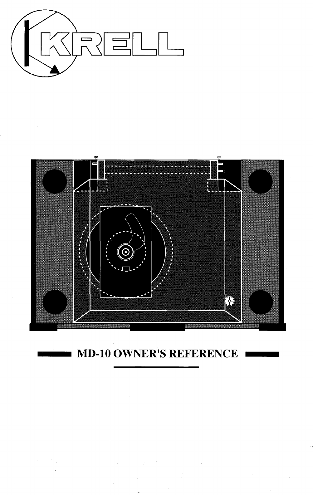
MD-10 OWNER’S REFERENCE
Page 2
A. INTRODUCTION
TCrOngratulations on your purchase of the MD-10 CD
anscription turntable and welcome to the KRELL
family oF audio components. You ha.vejoined a select
group of listeners who enjoy only tlae tlnest in music
reproduction.
We are dedicated to the~ development of technologically
advanced components tor the reproduction o.f digat~ly
recorded music and continuing the Krell tradition ot
uncompromised performance through leading-edge technology.
This Owner’s Reference is divided into several sections,
each designed to perform a different function. Basic
installation, operation and a Question and Answer section
are included, where answers to common questions are
provided. Should you have any questions or suggestigns,
i~lease feel free to contact your authorized dealer or tlae
KRELL staff for assistance.
In the unlikely, event that your.MD-1.0 should require
service you will be pleased~ to l~n~ ow tlaat it is backed by a
c.omprehensive Customer batistaction policy and one of
tlae most advanced service facilities in the industry, bor
detailed information on the terms and conditions of ser-
vice please consult your warra..nty registration card or
your authorized KRELL Distributor.
2
Page 3
B. TABLE OF CONTENTS
3
UNPACKING AND ASSEMBLY
4
DUST COVER INSTALLATION
6
BASIC INSTALLATION AND CONNECTIONS
9
OPERATION OF THE CD TRANSPORT
11
12
15
16
18
19
REMOTE CONTROL
TRACK AND FTS PROGRAMMING
MAINTENANCE
QUESTIONS AND ANSWERS
SPECIFICATIONS
WARRANTY AND SERVICE INFORMATION
C. UNPACKING AND ASSEMBLY
1. Open the box and remove the top layer of protective
foam. The following items will now be visible:
1 Dust Cover encased in a protective sleeve
1 CD Stabilizer
1 AC power cord
1 MD-10 RC Remote Control
1 Packet containing the Owner’s Reference and warranty
card
NOTE: If any of these items are not included, please
contact your authorized dealer immediately for assistance.
2. Remove the layer of foam containing these items and
set it aside for later use. Carefully remove the MD-10
from its box and remove the protective plastic wrap.
NOTE: Save all packing mate.rials. If you must ship your
MD-10 in the future, repack the unit in its original pa,ckaging to prevent transit damage. If the unit is re.turned to
KRELL for service, please send the cover and tlae remote
control unit.
CAUTION: Do not remove the acrylic dust cover from its
protective sleeve at this time! This cover is extremely
~lelicate and ca.n be permanently scarred if mishandled.
Please follow tlae instructions provided in this Reference
for safe installation.
3
Page 4
D. DUST COVER INSTALLATION
1. Looking at the front of the MD-10, locate the two
black hinge block assemblies on the rear left and right
corners. (Refer to location diagram)
2. Locate the hinge pin on the back of each hinge block
assembly and pull them out gently until they are fully
extended.
t3
Open the flap only on the protective sleeve and locate
h.
e three cover pins.
4. Place the cover over the unit and insert the cover into
the hinge block assemblies with the cover in the ~
u~ri~ht ~osition. Make sure all three pins are in there
proper receptacles. Refer to location diagram on page 5.
5. Lock the cover into the hinge blocks .by pushing the
pins into them until they are fully seated.
6. Gently pull the cover forward and let it go, allowing
the cover to slowly descend.
CAUTION: Do not push the dust cover down. Its damping system allows a slow descent, and can be damagedif
force is applied.
7. Remove the protective sleeve.
4
Page 5
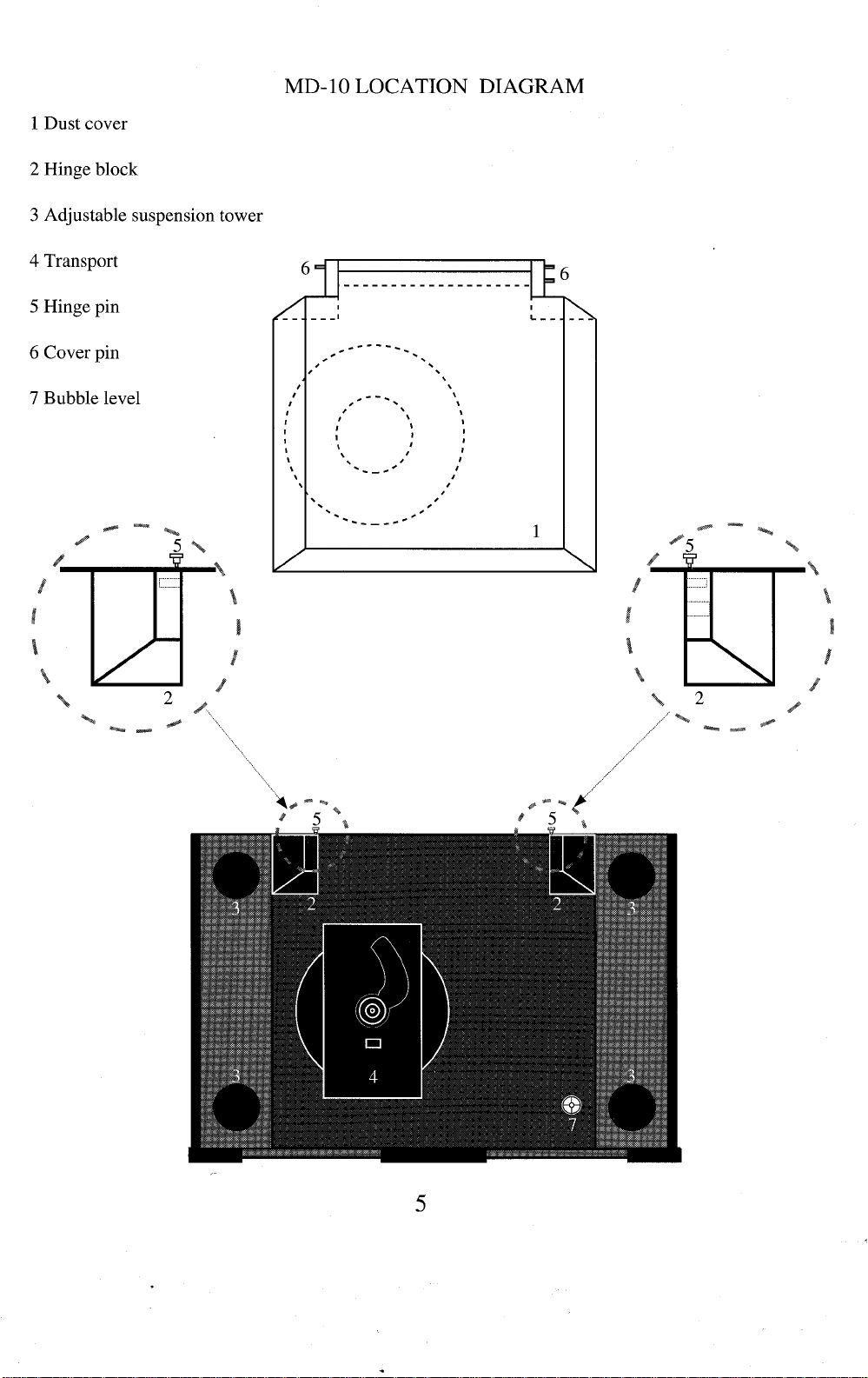
1 Dust cover
2 Hinge block
3 Adjustable suspension tower
4 Transport
5 Hinge pin
6 Cover pin
7 Bubble level
MD-10 LOCATION DIAGRAM
5
Page 6
E. BASIC INSTALLATION AND
CONNECTIONS
1. Place the unit on a clean, level surface away from
excessive heat, moist.ure or light. Ideally, the MD-10
should be placed on tlae top of an audio component cat)i-
net or other "open air" rigid platform.
2. The MD-10 may. be. placed in a cabinet. It will require.
17.0 inches of vertical clearance between the bottom anti
top shelves for proper operation of the cover.
3. If. space is limited, the MD-10 can be operated without
its clust cover. Six inches vertical clearance is adequate to
allow convenient access to the disc transport area.
4. The location of the unit should be within 2 meters of
the digital signal proeess0r~ If longer distanc.e is re_quired,
we recommend using an AT&T fi.~re optic clata linl~ o.r an
AES/EBU balanced ~lata.link, as tlaey are more suitecl to
long distance runs. --~
5. Once you have found a location for the unit, adjust the
transport’s a_djustable suspension towers to make the
MD--10s surffice level. A bubble level is conveniently
mounted in the black acrylic, tOl~ plate, allowing for easy
level adjus.t.ment, Adjust eacla ot the four suspension
towers until the bublSle in the level is centered. Counter
clockwise rotation raises the towers and clockwise rotation lowers the towers.
NOTE: The adjusta.ble suspension towers are only for
fine a.djustment anti can not compensate for gross surface
irregularities.
6. Connect the AC power cord to the back of the unit.
Once the power cord is secured, plug the cord into an AC
outlet.
7. Press the POWER button on the front panel. The display will illuminate and the transport will now be active.
NOTE: While the MD-10 has superb regulation and does
not require a dedicated AC circuit, we strongly advise
against any. connections through extension cords or multiple AC a~laptors. High quality 15 amp grounded AC
strips are acceptable.
6
Page 7

8. Connect the Digital Output from the MD-10 to a Krell
Digital Processor or other compatible digital-to-analog
audio processor.
The MD-10 is compatible with industry standard Fibre
~O_[?tic, Coaxial RCA, AT&T wide bandwidth Fibre Optic
~1 type and AES/EBU XLR output connectors.
NOTE: Care should be taken in selecting the type of
cable used to lin.k the MD,10 to your processor. We
recommend botla the AT&T Fibre Optic due to its superior bandwidth and signal isolation properties, and ttie
AES/EBU format due to its higher voltage transmission
and noise rejection due to balanced format.
CAUTION: The MD-10 is a CD Transport only. It is not
designed to connect directly to any preamp or analog
signal processor.
The MD-10 is equipped with a sp.ecial terminatiop system called TimeSync. TimeSync is a system that locks.
the clock between the MD-10 and specific Krell digitalto-analog processors. This connection is labeled
SPECIAL on the back of the MD-10. The termination is
via an AT&T fibre optic cable only and is used in con-
junction with any of-the other digital links like the AT&T
or AES/EBU.
NOTE: The TimeSync system can ~ be utilized with
certain Krell digitaI-to-analog converters and will not
work with any other make or model. Please consult your
dealer or the Krell staff for specific information.
NOTE: The TimeSync output can not be used as an addi-
tional digital output.
TIMESYNC CONNECTION
The TimeSync system is terminated via an AT&T ST
fibre optic cable.
1. Connect the AT&T fibre optic cable to the termination
labeled SPECIAL on the MD-10. Make sure the small
key at the top of the fibre optic cable is upright and fits
smoothly into the AT&T receptacle, twist the collar
clockwise to lock the cable in place.
2. Connect the free end of the fibre optic cable to the
termination labeled TimeSync/Ext clock on the back of
your Krell digital-to-analog converter.
7
Page 8

3. Connect your digital interlink between the transport ,
and digital-to-analog converter, if not already connectecl.
4. Select a digital source and press the TimeSync button
on the front of your digital-to- analo~ converter. The
corresponding led will-illuminate indicating the
TimeS-ync is locked. Should the TimeSync-LED flash,
tlais means the TimeSync clock has not locked and. requires, resetting. Select any other digital input.on tlae
digital-to-analog converter and then reselect the input,
you. wisla to use. The TimeSync LED will now be steacly
and the clock will be locked.
Page 9

F. OPERATION OF THE CD
TRANSPORT
1. Turn the CD transport ON by pressing the Power
b.utton., The display will illuminate. Select a disc an.d
place it on the spindl~e, label side up. Put the disc st.alfi-
fizer on the center ot the CD so it fits securely on tide
drive spindle.
CAUTIONS: Never operate the CD transport without the
disc stabilizer. This can result in damage to the transport
or your valuable compact discs.
b. Never place the disc stabilizer where the cover may
accidentally close on it and damage the cover.
c. Do not use any disc stabilizing tool besides the Krell
CD Stabilizer. Th.is device has been specially machin.ed
to precisely matcla the CD transport. Failure to heed tlais
warning may cause damage to the laser transport.
2. The functions of the front panel buttons that control
the transport are described below.
POWER
STOP
PLAY
PAUSE
TRACK I<
TRACK >1
INDEX I<
INDEX >1
SEARCH I<
SEARCH >l
FTS
PROGRAM
Turns unit ON or OFF
Stops the disc from playing
Starts the disc playing at. track 1;
will also restart play of tlae
current track
Tem.porarily stops play of current
track
Reverse track select
Forward track select
Reverse index select
Forward index select
Fast reverse search
Fast forward search
Programs FTS memory; will also play
FTS- encoded discs
Stores selected tracks in memory
REPEAT
Starts play from the beginning once
disc has finished
9
Page 10

3. Select a track on the CD to play with the remote control or via the front panel and press the Play button. The
music will now began.
10
Page 11

G. REMOTE CONTROL
1. The operating functions of the Remote Control are
describei] below:
POWER
STOP
PLAY
PAUSE
TRACK I<
TRACK >1
INDEX I<
INDEX >l
SEARCH I<
SEARCH >l
FTS
PROGRAM
Turns unit ON or OFF
Stops the disc from playing
Starts the disc playing at. track 1;
will also restart pray of the
current track
Tem.porarily stops play of current
track
Reverse track select
Forward track select
Reverse index select
Forward index select
Fast reverse search
Fast forward search
Programs FTS memory; will also play
FTSencoded discs
Stores selected tracks in memory
RPT
2. The MD-10 remote control has a 10 .d_i.git keypad. The
keypad allows for direct access to specific tracks. Pu,nch
in tlae [rack number you want and press Play, tlae track
you selected w_ill begin playing. The direct access keypad
IS convenient tor track and FTS programming.
Starts play from the beginning once
disc has finished
11
Page 12

H. TRACK PROGRAMMING
The remote control or the front panel of the MD-10 can
be used to program specific tracks on a disc to be played
in the order you choose. The MD-10 can store up to 20
selections per program.
1. Select the track number which will start the sequence
into the keypad, then push the PROGRAM or PROGR
button. A ’~" will appear next to the track number.
2. Enter the rest of the track selections in. your program in
the same manner remembering, to push the program
button after each track selected.
3. Once you have finished your program.m, ing: push the
PROGRAM or PROGR button again ending the program
sequence. The machine will then review the tracl~s you
have selected.
4. Press the PLAY button and the program will begin.
While the.progr.am is running you can Pause, Search. and
select tracks within the prog_ram. You can start a track
playing from the beginning by pressing the Play button.
P.ress STOP only to ~tefeat, or erase, ttie program function.
5. Press. the .REPE.AT button and the machine will play
your selected tracks over again in the same order tlaey
were programmed.
6. To cancel your program push the STOP button.
FTS MEMORY
FTS, or Favorite Track Selection, is a feature that enables
you to store desired tracks on a CD, in a sp~ecific order,
into the memory of the MD- 10. Once you have pro.-
grammed a disc with FTS, the machine will give that
specific CD a reference number. The machine remembers
.tfiis information and will play the tracks you have selected for that CD with a simple command. The machine
can also play the entire disc should you choose.
12
Page 13

FTS PROGRAMMING
To program tracks in the FTS memory:
NOTE: Before you begin,place disc to be progra.mmed
on the unit and press PLAY. Once the unit reacls the table
of contents and displays the disc’s playing_ time,press
STOE You can now begin programming the FTS
memory.
1. Program the selections in the standard form described
above.
. After you have progra.mmed the tracks, press the FTS
~
utton on the front panel or on the remote control. The
FTS indicator in the display will flash.
b3. While the indicator is flashing, press the PROGR .AM
utton. The machine will then display a number on the
screen briefly. This is the FTS designation number. When
this number appears the FTS programming is complete.
N.O.TE: You may want to label.the disc you programmed
with the FTS designation number so it can easiIy be
erased or changed-in the future.
4. You can now start playing your FTS programmed disc.
TO PLAY AN FTS DISC
1. Press the FTS button on the remote or front panel
before you press PLAY.
2. The FTS indicator on the display will flash.
3. While it is flashing, press the PLAY button and the
.MD-10 wi.ll play_ only the tracks in FTS memo.ry. If you
clo not wish to play.only the FTS selected tracks o~n. a
disc, press Play with out pressing the FTS button first.
The entire disc will now play.
13
Page 14

TO ERASE FTS PROGRAM MEMORY
NOTE: FTS memory can only be erased via the front
panel controls. The remote control cannot erase FTS
memory.
NOTE: The disc does not have to be on the MD-10 to
rase FTS memory. Erasure can be completed with no
~
isc on the drive spindle.
. Press the FTS button on the front panel. Hold the .
~
u.tton in while pressingthe forward or backward track
select. You will notice t-he machine is scrolling through
F.TS designation.numbers. Once you have found the FTS
.designatio.n numt)er you want to erase, press the STOP
button and the program will be erased.
14
Page 15

I. MAINTENANCE
.B.e.cause of its superb build quality the MD-10 requires
little maintenance. Should tlie unit become excesslvly
dirty, clean the lens assembly with a camera lens brush
made of a soft material like camel hair. The acrylic top
p!ate and dust cover should be cleaned with the poli~stiing
.kit provided. Read the directions on the containers tor
best polishing results.
REMOTE CONTROL BATTERY INSTALLATION
AND REMOVAL
The batteries in the remote control should be changed
when the tran.sport is no longer un.derstaqding .or cor-
rectly responding to the commanOs sent trom tlae unit.
R~e .move the four socketcap screws from the back portion
ot tlae remote control. Remove the back plate to expose
the battery storage compartment. Refer to the polarity
drawing.w, hile inserting the batteries. Replace the back
plate and insert the four socketcap screws.
FUSE INSTALLATION AND REMOVAL
If the MD-10 does not seem to power-up, unplug the unit
from the AC wall socket and check the fuse.
1. Locate the fuse holder on the back of the unit labled
FUSE. Turn the fuse holder counter clockwise and gently
pull the fuse free from the chassis.
2. Check to make sure the foil in the center of the fuse is
still connected. If you are still unsure, measure the fuse
with an ohm meter to determine if it is intact. The MD-10
uses a 1 amp fast-blow fuse at l15v and a .5 amp fastblow fuse at 220v. Should the fuse need replacing, use
only the fuse specified.
3. Place the fuse into .the receptacle and push and tu.m
gently clockwise until the fuse holder is .~ully seated.
Plug the unit into the AC wall socket and press the Power
button.
CAUTION: Should the MD-10 n.ot powe~r-up and
con.tinously blow fuses, unplug the unit tro.m, the AC wall
outlet and contact your Kre-ll dealer or distributor.
15
Page 16

J. OUESTIONS AND ANSWERS
Q. My Digital to Analog ~processor will accommodate
either fibre optic or coaxial digital inputs. Which output
should I use on the MD-10?
A. While a high quality coaxial willperform quite well,
we re.commend glass fibre optic cabre due to its ab.ility to
completely isolate the grounding planes between the.
transport and processor, and its resistance to RF interterence. If an AT&T or AES/EBU input is available, we
recommend one of these interfaces be utilized.
IQ. When listening to certain discs I hear skipping noises.
s there something wrong with the MD-10?
A. Due to the accuracy of the laser reading system in the
MD-10, discs must be kept reasonably clean. If the disc
is mistracking, it could be because of excessive dirt or
fingerprints. Clean the disc and retry. If the disc still
s~ps, try several others. If it is only the first disc that is
skipping, the disc may. need to be replaced. If the unit
mistracks on several discs, contact your Krell dealer or
distributor.
Q. ! can not seem to get the FTS programming feature to
program my discs, is there something wrong?
A. Make sure the disc you wish to program is indexed, or
read, by the machine before you start your program.
Refer to the FTS programming instructions in this refere.nce..Make sure when you are playing FTS encoded
cliscs tlaat the FTS button is pr.essei:l and the display reads
FTS. If the sequence is altered the MD-10 can not correctly correlate the FTS information.
tQ. Do you recommend I leave the MD-10 ON at all
lmes?
A. Yes, These circuits are most accurate and stable when
left to idle when not in use. In fact, discrete parts age
.faster when cycled ON and OFE The MD-10 will sound
better and last longer if left ON.
NOTE: You should disconnect the AC cord from the wall
outlet before any electrical storms or if you plan to be
away from your home for prolonged periods of time.
Q. Will the MD-10 play if the dust cover is fully raised?
A. Certainly. The unit will function perfectly even with
the dust cover removed.
16
Page 17

t~. Due to the exposed nature of the laser assembly is
ere a possibility of damage through laser radiation?
A. No. There is. an optical sensor under the CD when it is
positione~l on tlae transport hub. This allows the MD-10
to p.rohibit the laser from turning on wlaen it is not cov-
erecl with a CD.
a~I own many CDs that have CD Rings on them. Am I
le to use these discs with the MD-I(~?
DA. Yes, The MD-10 will accept discs with :’CD Rin.gs".
ue to their very low mass, they will not clamage t~ae
MD-10’s transport. While we can neither affirm nor deny
the benefits dei~ved from the use of CD Rings, we do not
fee! that any type of disc equilibrium device is require.d
witla the MD-10 when properly used with our CD Stabi-
lizer.
CAUTION: We strongly advise against the use of any
type.of additional disc stabilizer. These items add too
mucla mass to the laser servo system and may burn out
the drive.
.Q. Do you recommend the use of Cones or other damp-
ing feet with the MD-10?
A. Due to the extraordinary rigidit.y of our machining and
internal damping, we do not f6el tlaat the MD-10 requires
addit~ional m.ass co.upling or isolation. If you wish to use
an atter-marl~et isolation device, you may do so without
fear of dam. agingthe MD-10. Any device which affixes
permanently to the chassis.or requires a breach of the
external chassis will void tlae warranty.
NOTE: Before any type of. after market device is to be
utilized in conjunction witla the MD-10, please consult
your dealer or the Krell staff for assistance.
tQ. Can I use more than one digital output at the same
lme?
A. Yes, The MD-10 can drive up to four different digital
to analog converters.
Q. Will the MD-10 play CD singles?
A. Yes, the MD-10 will play CD singles.
17
Page 18

K. SPECIFICATIONS
TRANSPORT
Modified Philips CDM-4 PRO with Hall effect motor,
swing-arm design
LASER
Single Beam with glass lens
OUTPUT
Digital only in industry standard SP_DIF format.
1 FIBRE OPTIC via standard intertace
1 COAXIAL via RCA connector
1 AT&T via ST connector
1 AES/EBU via XLR connector
1 SPECIAL Optional TimeSync via ST
connector
REMOTE CONTROL
Wireless infrared
DIMENSIONS
19.0" wide,
12.5" deep
6.0" high, cover closed
15.0" hfgh with cover open
WEIGHT
20 pounds unit only
34 pounds in box
18
Page 19

L. WARRANTY AND SERVICE
INFORMATION
There are no user-serviceable parts inside the MD-10.
The MD-10 has a limited warranty of three years parts
and labor on transport-related parts; five years parts an.d
labor on electronic parts, lleturn freight is included in the
warranty. The warranty period b.egins on thee date of
p_u_rchase and is activated with the return ot the enclosed
warran.ty Card and a copy of the Sales receipt. Please
return the warranty card-immediately after successful
installation and operation are completed.
The warranty for Krell products is valid ~ in t.he count~ry to which they were originally shipped and at the
ta.ctory. If you think there are problems with your unit
please contact your dealer, distributor or the factory
immediately.
he operating voltage of this unit is deterro, ined by the
~a
cto_ry_ and c.a.n only be changed by_ an authorized
KRELL distrit)uter or the KRELL factory. Any unautho[~zed volta.ge co.nversio~n will void the warranty. Should
e operating voltage ot your MD- 10 require changing,
contact KRELL Industries.
Plea_s.e do not returl? any unit to KRELL for repair with-
out first calling to discuss the problem and to obtain a
Return Authorization number.-Freight to the factory or
distributor is your responsibility. Return freight to you
will be paid by the factory or distributor. Any unautho-
r.ized disassembly,.updates or modifications performed to
the unit will voidthe warranty.
19
Page 20

0
0
I
0
I
0
’ DIGITAL INC.
\
KRELL DIGITAL INC.
35 HIGGINS DRIVE MILFORD CT 06460
SALES 203-874-3139 FAX 203-878-8373
COPYRIGHT 1992 KRELL DIGITAL INC.
(MD109209)
 Loading...