

Page 1
The Leader in
Engineering
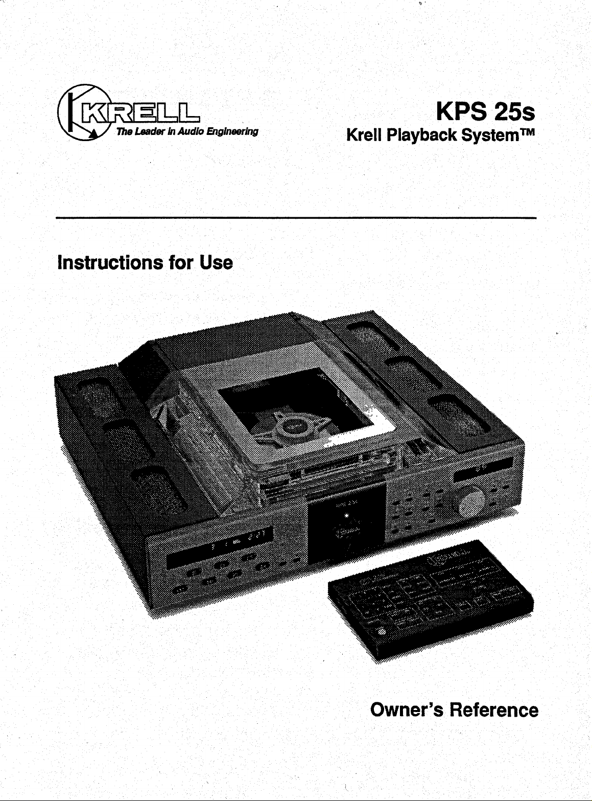
Instructions for Use
KPS 25s
TM
Krell Playback System
Owner’s Reference
Page 2
KPS 25s
TM
Krell Playback System
CONTENTS
Page
INTRODUCTION 3
UNPACKING 3
Krell®lndustries, Inc.
45 Connair Road
Orange, CT 06477-3650
TEL 203-799-9954
FAX 203-799-9796
E-MAIL krell@krellonline.com
www.krellonline.com
USA
PLACEMENT
AC Power Guidelines 4
INSTALLING THE ACRYLIC COVER 4
CONNECTING THE KPS 25s
TO YOUR SYSTEM
Additional Connections 11
REMOTE CONTROL OPERATION 11
How to Write a Program 12
Battery Installation and Removal
MENU FUNCTIONS 15
WARRANTY 17
RETURN AUTHORIZATION
PROCEDURE 18
SPECIFICATIONS 20
14
4
8
INSTALLING THE ACRYLIC COVER
ONTO THE KPS 25s BACK PANEL 5-7
THE KPS 25s BACK PANEL 8
THE KPS 25s FRONT PANEL
THE KPS 25s TABLETOP REMOTE
CONTROLLER 10
THE KPS 25s HANDHELD REMOTE
CONTROLLER 11
© 1998 by KRELL® Industries, Inc. All rights reserved
9
P/N 1960101900100
Page 3
CE Marking Unpacking
This product complies with the EMC direc- 1. Open the shipping box and remove the
tire (89/336/EEC) and the low-voltage top layer of foam. You will see these items:
directive (73/23/EEC).
Introduction
Thank you for your purchase of the Krell
KPS 25s Krell Playback System
KPS 25s is an integrated design incorporat-
ing a compact disc player, a preamplifier,
and a digital-to-analog converter in one
chassis.
To obtain the best performance from your
KPS 25s, pay careful attention to its placement, installation, and operation. A thorough understanding of these details will
help insure satisfactory operation and long
life for the KPS 25s and related system
components,
THERE ARE NO USER-SERVICEABLE
PARTS INSIDE ANY KRELL® PRODUCT. tance.
Please contact your authorized dealer,
distributor, or Krell
questions not addressed in this reference manual.
®,
if you have any
TM.
The
NOTE: If any of these items are not includ-
ed in the box, please contact your authorized Kre//edea/er or distributor for assis-
2. Carefully remove the unit and acces-
NOTE: Save all packing materials, ff you
ship your KPS 25s in the future, repack the
unit in its original packaging to prevent tran-
sit damage.
KPS 25s chassis
Acrylic Cover in velvet pouch
KPS 25s Handheld Remote
Controller
KPS 25s Tabletop Remote
Controller
package of ~ batteries
Disc Clamp
AC power cord
12 Vo=t remote cable
T-10 Torx wrench
cleaning kit for the Acrylic Cover
packet containing an introductory
letter from Dan D’Agostino,
C.E.O., the Owner’s Reference,
and the Warranty Registration Card
sories from the box. Remove the protective plastic wrap from the unit.
KRELL® KPS 25s English Page 3 of 20
Page 4
Placement
WARNINGS
The Krell Playback System
located where it could be exposed to drip-
ping or splashing fluids.
Before you install the KPS 25s into your
system, review the following guidelines to
choose the location for the KPS 25s. This
will facilitate a clean, trouble-free installation.
The KPS 25s does not require a special rack
or cabinet for installation. Forthe dimensions
of the KPS 25s see Specifications on page
20.
1. Place the KPS 25s on a firm level surface, away from excessive heat, humi-
dity or moisture.
2. The KPS 25s incorporates an advanced suspension system and does not
require additional mass coupling or isolation. You may experiment with feet
or cones as long as they are not perma-
nently affixed to the chassis. Any unau-
thorized modifications to the electronics
or chassis will void the warranty.
IMPORTANT: Please do not attach
enhancement accessories such as rings,
mats, or dampers to individual CDs. These
TM
must not be
accessories may cause problems with the
transport mechanism, resulting in erratic
playback and/or poor sound.
AC Power Guidelines
WARNING
Do not remove or bypass the ground pin on
the end of the AC cord. This may cause RFI
(radio frequency interference) to be induced
into your playback system.
The KPS 25s has superb regulation and
does not require a dedicated AC circuit.
Avoid connections through extension cords
or multiple AC adapters. High quality 15 amp
grounded AC stdps are acceptable. High
quality AC line conditioners or filters can be
used if they are grounded and meet or
exceed the unit’s power supply rating of 100
VA.
Installing the Acrylic
Cover
Install the Acrylic Cover onto the top of the
KPS 25s, before connecting the KPS 25s to
your system. Follow the easy steps outlined
on pages 5, 6, and 7.
Page 4 of 20 English
KRELL® KPS 25s
Page 5
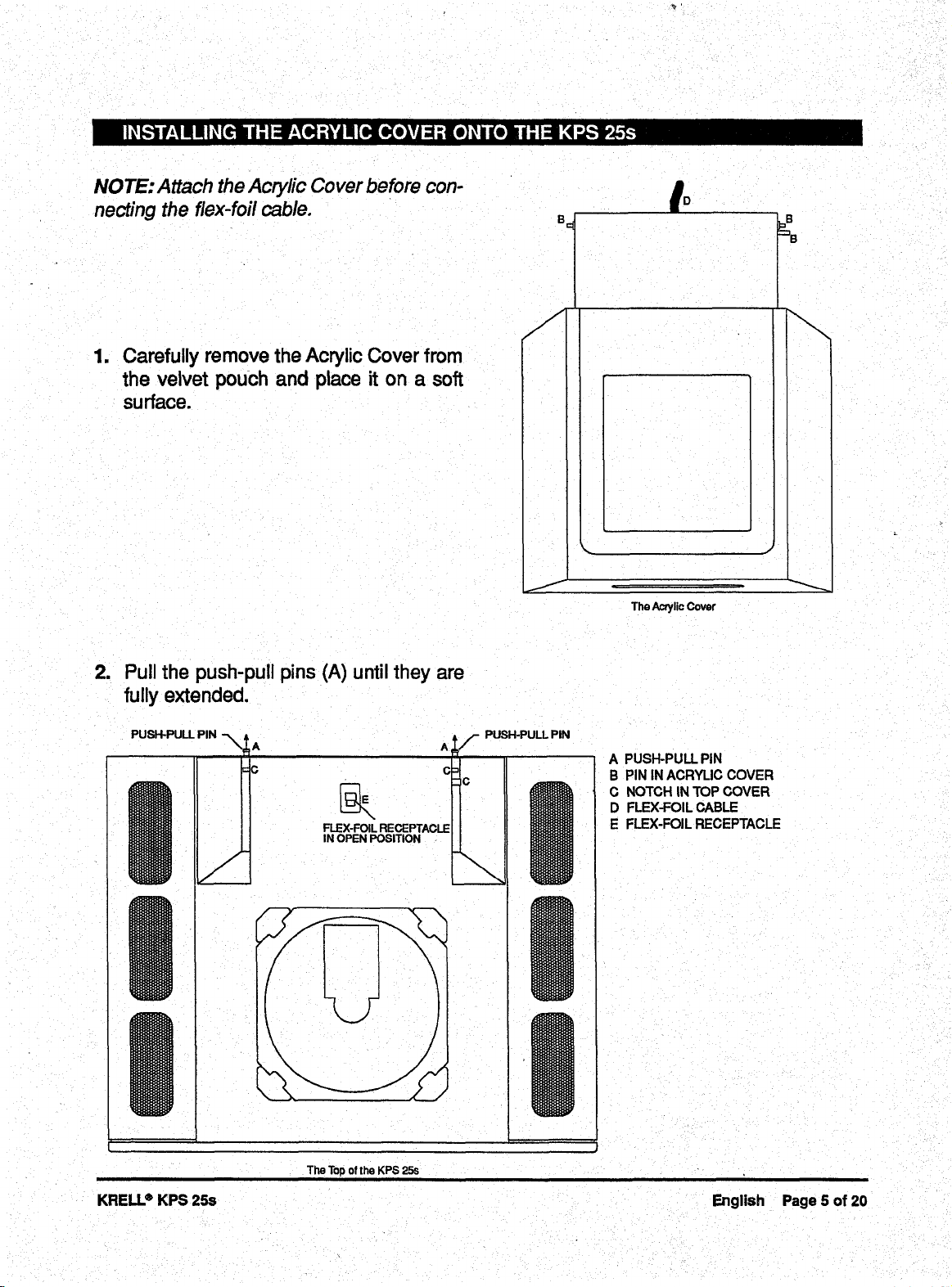
NOTE: Attach the Acrylic Cover before connecting the flex-foil cable.
Carefully remove the Acrylic Cover from
the velvet pouch and place it on a soft
surface.
The Ac~lic Cover
2. Pull the push-pull pins (A) until they are
fully extended.
PUSH-PULL PIN -~ A A
FLEX-FOIL RECEPTACLE
IN OPEN POSITION
PUSH-PULL PIN
A PUSH-PULL PiN
B PIN IN ACRYLIC COVER
C NOTCH IN TOP COVER
D FLEX-FOIL CABLE
E FLEX-FOIL RECEPTACLE
KRELL® KPS 25s
The "lop of the KPS 25s
English Page 5 of 20
Page 6
INSTALLING THE ACRYLIC COVER ONTO THE KPS 25s, continued
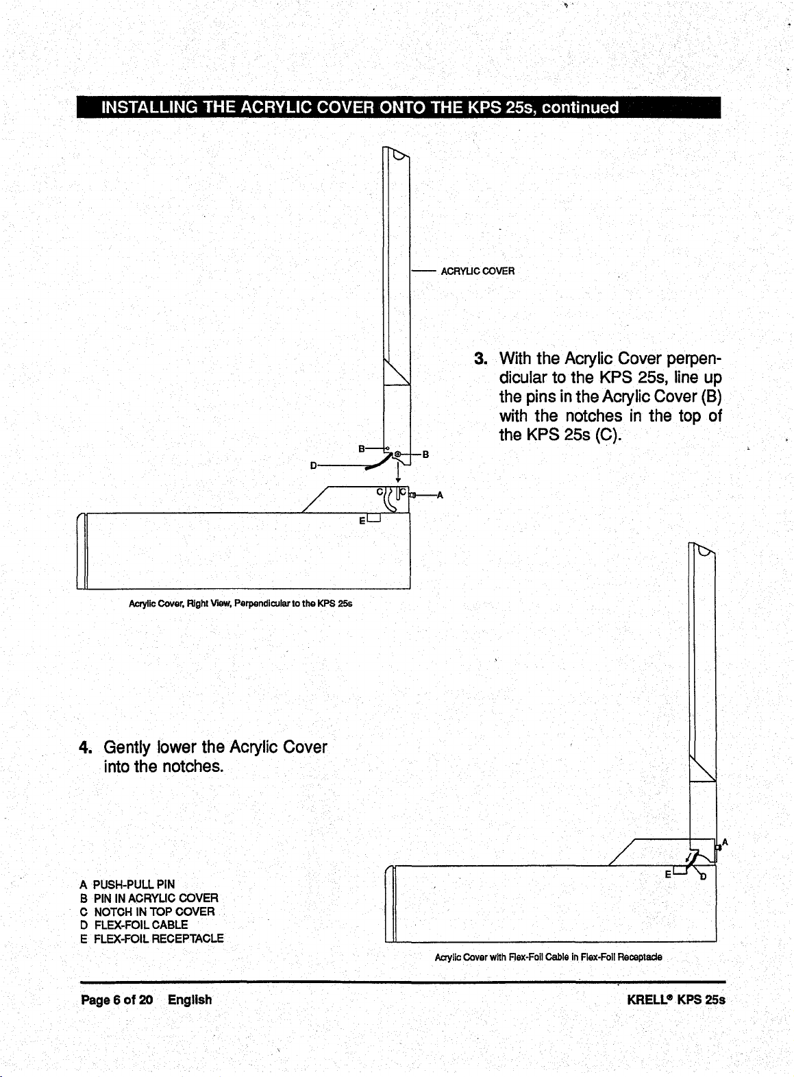
ACRYLIC COVER
With the Acrylic Cover perpen-
3.
dicular to the KPS 25s, line up
the pins in the Acrylic Cover (B)
with the notches in the top of
the KPS 25s (C).
Acrylic Cover, Right View, Perpendicular to the KPS 25s
Gently lower the Acrylic Cover
=
into the notches.
A PUSH-PULL PIN
B PIN IN ACRYUC COVER
C NOTCH IN TOP COVER
FLEX-FOIL CABLE
D
E FLEX-FOIL RECEPTACLE
Acrylic Cover with Rex-Foil Cable in Flex-Foil Receptacle
Page 6 of 20 Engllsh KRELL® KPS 25s
Page 7

INSTALLING THE A(;RYLIC COVER ONTO THE KPS 25s continued
PUBH-PULL P’N
~
(
)
A
PUSH-PULL PIN
B PIN IN ACRYLIC COVER
C NOTCH IN TOP COVER
D FLEX-FOIL CABLE
E FLEX-FOIL RECEPTACLE
The "lop o] the KPS 25s with Acrylic Cover and Flex-Foil Cable in Piece
Push the push-pull pins (A) into the
5.
closed position.
6. Make sure the flex-foil receptacle is in
the open position. Feed the flex-foil
cable (D) attached to the Acrylic Cover
back toward the flex-foil receptacle (E)
on the top of the KPS 25s. Carefully
align the flex-foil cable so the tip of ~the
flex-foil cable is parallel to the flex-foil
receptacle.
7. Insert the flex-foil cable into the flex-foil
receptacle (E). Close the flex-foil recep-
tacle by sliding the flex-foil receptacle
sleeve toward the transport. There will
be an audible "click" when the flex-foil
cable is locked in position.
KRELL® KPS 25s English Page 7 of 20
Page 8

Connecting the KPS 25s
to Your System
WARNING
When making connections to this component or any other, make sure the power
amplifier is Off. Make sure all cable terminations are of the highest quality, free from
frayed ends, shorts, or cold solder joints.
1. Connect the outputs of associated
source equipment to the inputs of the
KPS 25s.
2. Connect the left and right outputs of the
THE KPS 25s BACK PANEL
KPS 25s to the appropriate associated
equipment.
When connecting the KPS 25s to AC
3.
power, first connect the EIC Standard
15 amp AC power cord between
the KPS-25s and the wall socket. Then
switch the power on from the Rear
Panel Power Switch. The word KRELL
will momentarily appear in the Menu
Display Window located on the dght
front panel of the KPS 25s. This indicates that the KPS 25s has initialized
and is ready for operation. The unit is in
Stand-by mode.
1 Left and right balanced Inputs 11
2 Inputs from tape deck
3 Outputs to tape deck
4 Single-ended input 1
5 SinglHnded Input 2
6 Single-ended input 3
7 Acrylic Cover damper adjust-
ment corrtrol
8 Rxed level balanced outputs
9 Variable level balanced
outputs
Fixed level single-ended
10
outputs
1 2
3 7
Variable level single-ended 17
outputs
KrelP CAST
12
able level outputs for use with
other KrelP CAST
components)
13
BAJ fiber optic digital outputs
(via TosLink
14
SPDIF co-axial digital outputs
(via RCA connectors)
AES/EBU digital output (via an
15
XLR connector)
16
BAJ fiber optic digital inputs
(via TosLink
TM
outputs (vari- 18
TM
equipped
TM
connectors)
TM
connectors)
SPDIF co-axial digital Inputs
(via RCA connectors)
AES/EBU digital input (via an
XLR connector)
19
Main on/off power switch
20
Fuse holder
21
IEC Standard 15 amp AC
power cord receptacle
22
KrelP RemoteLink
nications output data pert
23
KrelP RemotaLlnk
nicatlons input data port
RC-5 baseband Input
24
25
12 Volt trigger output
TM
TM
commu-
commu-
1 4 5 6 10811
Page 8 of 20 English
KRELL® KPS 25s
Page 9

The KPS 25s is equipped with the following
analog and digital inputs:
The KPS 25s is equipped with the follow-
ing analog and digital outputs:
1 set of balanced analog inputs (via
an XLR connector)
3 sets of single-ended analog inputs
(via RCA connectors)
1 set of tape monitor analog inputs
2 EIAJ fiber optic digital inputs (via
TosLink
SPDIF co-axial digital inputs Ivia
2
TM
connectors)
RCA connectors)
1
AES/EBU digital input (via an XLR
connector)
Compact Disc Transport 12
Display Window
2 Transport Pause button
Transport Play button
3
4 Transport Stop button
Transport HDCD’ Indicator light
5
6 Transport SYNC~ Indicator light
Transport Search Back button
7
8 Transport Search Forward
button
9 Transport Track Back button
Transport Track Forward
10
button
11 Transport Drive On/Off button
13
14 Compact disc player Input
15 AES/EBU Input selector button
16 EIAJ fiber optic digital input
17 SPDIF co-axial input selector
18 SPDIF co-axial input selector
19 EIAJ fiber optic digital input "
20 Single-ended input selector
1 set of fixed balanced outputs (via
1 set of variable balanced outputs (via
1 set of fixed single-ended outputs
1
1
2 EIAJ fiber optic digital inputs (via
Main power button
Operating Indicator light
selector button
selector button
button
button
selector button
button
an XLR connector)
an XLR connector)
(via an RCA connector)
set of variable single-ended outputs
(via an RCA connector)
set of KrelP CAST
TM
outputs (via
4-pin bayonet connector)
TosLink
TM
connectors)
21 Balanced input selector button
22 Single-ended input selector
button
23 Single-ended Input selector
button
Tape deck Input selector
24
button
25 Level control knob
26 Menu display window
27 Fixed output mute selector
button
28
Variable output mute selector
button
29 Menu control button
=
30 Absolute phase Indicator light
2 1 3 4 5 6
7 8 9 10 11 12
HDCDe is the registered trademark of Pacific Microsonics, Inc.
Indicates that the digital date is functioning properly.
Illuminates when the absolute polarity of Ihe main output is invarted 180",
KRELL® KPS 25s
13
KPS 25s
14 15 1 26 27 28
20 23
16 19 24 25 29 30
English Page 9 of 20
Page 10

SECTION 1 SECTION 2 SECTION 3
KPS 25s
DIRECT AGCESS CONTROLLER
SECTION 4
SECTION 7 SECTION 6 SECTION 5
2 SPDIF co-axial digital outputs (via The XLR pin
RCA connectors)
below:
1 AES/EBU digital output (via an XLR
connector)
KrelP recommends the use of balanced
interconnects. Balanced interconnects not
only have the ability to minimize sonic loss
but also have immunity to induced noise,
especially for installations using long cable
The left and right channel RCA and balanced outputs are labeled on the back
panel. Please maintain the correct left/right
orientation.
Pin 1
Pin 2
Pin 3
configuration is described
lengths. Balanced connections have 6dB
more gain than single-ended connections.
When level matching is critical, keep this
specification in mind.
NOTE: Both ba/anced and single-ended
outputs can be used to simultaneously feed
different systems.
When the KPS 25s is connected directly to
a stereo power amplifier or a pair of monau-
ral power amplifiers, use the variable output
terminals to insure proper level control.
Ground
°)
Non-inverting (0
Inverting (180")
Page 10 of 20 Engllsh
KRELL® KPS 25a
Page 11

Using the fixed outputs in this configuration
may cause damage to associated power
amplifier and loudspeakers.
Additional Connections
RC-5
The RC-5 input makes custom installation
easy and secure by accepting baseband
RC-5 input commands from hardwired
remote controllers.
12 VDC OUT
The remote power output transmits 12 Volt
power on/off signals to other KrelP components, as well as to other components that
accept 12 Volt power on/off trigger com-
mands.
Remote Control Operation
The KPS 25s is equipped with two remote
controllers. The KPS 25s Handheld Remote
Controller provides the basic functions of
Power, Play, .Pause, Stop, Track, and Level.
The KPS 25s Tabletop Remote Controller,
named the Direct Access Controller, provides complete CD transport functions as
well as KrelP preamplifier and power ampli-
fier remote control functions. A description
of the buttons and their functions follows.
NOTE: The Tabletop Remote Controller
®
also includes functions used with Krell
amplifiers.
NOTE: Consult the owner’s reference of
the components used in a custom installa-
tion to take full advantage of the remote
capability of the KPS 25s.
THE KPS 25s HANDHELD REMOTE
CONTROLLER
V LEVEL /~
PAUSE PLAY STOP
I~ TRACK bl POWER
Section 1
Direct Number Access Keypad
The Direct Number Access Keypad makes
track selection quick and easy. When using
the direct track access function, the selected
track will begin play immediately after a
track is selected. If the track you want to
play is numbered 1-9, press the button that
corresponds to the track. Use the +10 button to access tracks numbered 10 or higher.
The +10 b~Jtton selects a track in incre-
ments of 10.
EXAMPLE: To access Track 8, press the
number 8 button once. To access Track 10,
press the + 10 button once and the 0 button
once. To access Track 24, press the +10
button twice and press the 4 button once.
Tracks consisting of two digits must be
keyed within eight seconds of each other.
KRELL® KPS 25s
Clear
Deletes the last entry selected in a pro-
grammed sequence.
English Page 11 of 20
Page 12

II
Section 2
Special Play Functions
Repeat
Press once to repeat the entire disc or track
program continuously. Press twice to repeat
the current track continuously. Press a third
time to cancel this function. When selecting
the desired Repeat function, press the
Repeat button once and REPEAT will
appear in the Compact Disc Transport
Display Window. Press the Repeat button
twice and REPEAT and SINGLE will appear
in the Compact Disc Transport Display
Window.
AJB
Creates a loop between two pre-determined
points within a single track or sequential
tracks. To create an A/B loop, start the play
of a track. When you hear the part that you
want as the beginning of the loop, press A/B
to insert the start position. Press NB again
to insert the finish position. A/B will auto-
matically begin and continue indefinitely.
Press Stop or A/B again to delete the A/B
program.
Access
When an exact start positions is critical, use
the Access button to numerically select a
position within a specific track program:
Track Programming
Track programming gives you the ability to
select the tracks you want to hear, in the
order in which you want to hear them. This
method of programming is short term and
will be cleared when you press the Stop
button twice. A maximum of twenty tracks
may be stored in a program sequence.
NOTE: Track Forward, Track Back, Repeat,
and Pause function normally within a pro-
grammed sequence.
Prog
Press once to access the track programming mode.
How to Write a Program
1. Press Program on the KPS 25s remote
control. PROGRAM will appear in the
Compact Disc Transport Display
Window.
2. Key in the desired track sequence using
the numeric keypad. Tracks consisting
of two digits must be keyed within
eight seconds of each other. The number of tracks and total playing time of
the programmed sequence will appear
in the Compact Disc Transport Display
Window. Track numbers will appear in
the Compact Disc Transport Display
Window in the order in which they are
stored within a programmed sequence.
Press Play to begin playback of a pro-
3.
grammed sequence.
4. Press the Stop button twice to erase a
programmed sequence.
Section 3
Digital Inputs
The KPS 25s has six digital inputs: CD,
AES, OPTICS 1, OPTICS 2, COAX 1, and
COAX 2. Press the appropriate button to
select the input that supports your source.
Section 4
Track Functions
Pause
Press once to temporarily suspends playing
the current track. Press the Pause or Play
button to resume playing the track at the
point Pause was engaged.
Page 12 of 20 English
KRELL® KPS 25s
Page 13

Play
To activate playback from the beginning of
the CD, press the Play button after inserting
the CD onto the transport. Clamp the CD
down, and close the Acrylic Cover. Playback
will begin from the first track. If the CD is
loaded and the disc contents have been
scanned, press Play on the front panel or
remote control. The disc will start playing
from Track 1 or the beginning of a pro-
grammed track sequence. When an
~
HDCI~ encoded CD is played, the HDCD
~
led illuminates, indicating that HDCD
decoding is functioning.
<<: Search Back
Perform a sustained press of the button to
scroll backward through the current track.
>>: Search Forward
Perform a sustained press of the button to
scroll forward through the current track.
Section 5
Volume Adjustment and Menu
Functions
Level U p and Down
Press to adjust the volume and to scroll
through menu functions.
Stop
Terminates CD playback.
I< I<: Index Back
Press once to select the index number prior
to the current index number within a spe-
cific track, if the CD has been recorded with
separate indexing.
>1 >1: Index Forward
Press once to select the index number following the current index number within a
specific track, if the CD has been recorded
with separate indexing.
NOTE: Some discs do not have index numbers programmed within tracks. When the
Index buttons are pressed, the display will
default to the current track number.
I<: Track Back
Press once to select and begin playing the
track that precedes the current track.
>1: Track Forward
Press once to select and begin playing the
track that follows the current track.
Balance Left and Right
Press to balance speakers.
Menu
Press to access menu functions. See also
Menu Functions page 15.
Fixed Mute
Press to activate. There is no signal on the
fixed output when the led on the front panel
of the KPS 25s is on.
Variable Mute
Press to activate. Th ere is no signal on the
variable output when the led on the front
panel of the’ KPS 25s is on.
Variable Phase
Press to invert the absolute polarity of the
main output 180 degrees. When the polarity is reversed, the led on the front panel of
the KPS 25s is on.
Section 6
Analog Inputs
The KPS 25s has five analog inputs. Press
the button to select the input that supports
your source. B-l, S-1, S-2, S-3, TAPE.
1HDCD~ is the registered trademark of Pacific Microsonics, Inc.
KRELL® KPS 25s English Page 13 of 20
Page 14

Section7 Drive Off
Amplifier and Display I/Vindow
Turns the CD transport On/off.
Functions Power
NOTE: Use the Amplifier Power and
The main power switch that turns the KPS
Amplifier Display buttons to access a Krell® 25s On/off.
amplifier connected to your system. These Battery Installation and Removal
buttons do not activate the KPS 25s.
Display Mode
Cycles the Compact Disc Transport Display
Window through three options: the elapsed
time of the track currently playing, the time
remaining in the current track, and the total
remaining time of the disc or program.
Press the CD button and then press the
Mode button. The options will appear in the
Compact Disc Transport Display Window
as they are selected.
NOTE: Batteries should be replaced when
functions activated by the remote controller
become intermittent. The KPS 25s Tabletop
Remote Controller uses four AAA size 1.5
Volt batteries. The KPS 25s Handheld
Remote Controller uses two AAA size 1.5
Volt batteries.
Remove the backplate to expose the
1.
batteries.
2. Remove the old batteries.
Display Dim
Turns the Compact Disc Transport Display
Window On/off.
Amplifier Power
Turns a KrelP remote controlled amplifier
On/off.
Amplifier Display
Operates the display of a KrelP remote controlled amplifier.
Install the new batteries, following the
3.
battery position diagram on the plastic
battery receptacle.
4. Re-install the backplate.
5. Check to make sure the remote control
is functioning properly.
Page 14 of 20 English
KRELL® KPS 25s
Page 15

Menu Functions
All initial set u p and subsequent system configuration adjustments may be made using
either the Tabletop Remote Controller, or the
front panel controls. Several menu features
that customize the KPS 25s are described
below.
To adjust the brightness of the Menu
Display Window:
1.
Press the Menu button. The word
MENU will appear in the Menu Display
Window.
4. Turn the Level Control Knob to select
the input to which you want to assign a
custom name.
5. Press the Menu bUtton. The word
PHONO will appear.
6. Turn the Level Control Knob to select
the desired name.
7. Press the Menu button to lock the
selected name to the selected input.
To exit the Menu mode completely,
8.
press the menu button again.
NOTE: The input for CD cannot be renamed.
2. Turn the Level Control Knob until the
word BRIGHT appears.
Press the Menu button again. The cur-
3.
rent brightness level will appear in the
Menu Display Window.
4. Turn the Level Control Knob to the left or
right to view brightness levels. The dis-
play may be set to mute the brightness
completely. When the brightness level is
set to the desired level, press the Menu
button one more time to lock the setting
in place.
5. To exit the Menu mode completely,
press the Menu button again.
To assign custom names to any of the
digital or the analog inputs of the KPS
25s:
1. Press the Menu button. The word
MENU will appear.
2. Turn the Level Control Knob until the
word NAME appears.
To select an input for Theater
Throughput~:
1. Press the Menu button. The word
MENU will appear.
2. Turn the Level Control Knob until the
word THEATER appears.
3. Press the Menu button again. The word
CD will appear.
4. Turn the Level Control Knob to select
TM.
the input for Theater Throughput
5. Press the Menu button again to display
the current theater mode setting.
When the display reads YES, Theater
Throughput
play reads NO, Theater Throughput
TM
is active. When the dis-
TM
is
inactive.
6. Turn the Level Control Knob to select
the desired theater mode setting.
7. Press the Menu button to lock the setting in place.
8.
Press the Menu button again. The word
3.
AESEBU will appear.
KRELL® KPS 25s English Page 15 of 20
To exit the Menu mode completely,
press the Menu button again.
Page 16

To change the shutter operation mode:
1. Press the Menu button. The word
MENU will appear.
2. Turn the Level Control Knob until the
word SHUTTER appears.
Press the Menu button again. The cur-
rent shutter operation mode will appear.
4. Turn the Level Control Knob to select
. the input for volume trim.
Press the Menu button again. The cur-
5.
rent volume tdm will appear.
6. Turn the Level Control Knob to select
the desired volume trim.
7. Press the Menu button to Iockthe setting.
4. Turn the Level Control Knob to select
the desired shutter operational mode.
5. Press the Menu button to lock the setting.
To exit the Menu mode completely,
6.
press the Menu button again.
To change the cover operational modes:
1. Press the Menu button. The word
To exit the Menu mode completely,
8.
press the Menu button again.
To change the volume control
sensitivity:
1. Press Menu button. The word MENU
will appear.
Turn the Level Control Knob until the
2.
words VOL SPEED appear.
MENU will appear.
Press the Menu button again. The cur-
2. Turn the Level Control Knob until the
word COVER appears.
Press the Menu button again. The cur-
3.
rent cover operational mode will appear.
4.
Turn the Level Control Knob to select
the desired cover operational mode.
5. Press the Menu button to lock the setting.
3.
rent volume speed will appear.
4. Turn the Level Control Knob to select
the desired volume speed.
5. Press the Menu button to lock the setting.
To exit the Menu mode completely,
6.
press the Menu button again.
To return all settings to factory default
6. To exit the Menu mode completely, values:
press the Menu button again.
To change an input’s volume trim:
1. Press the Menu button. The word
MENU will appear.
2. Turn the Level Control Knob until the
words VOL TRIM appear.
Press the Menu button again. The word
3.
CD will appear.
1. Press the Menu button. The word
MENU will appear.
2. Turn the Level Control Knob until the
words ALLCLEAR appear.
Press the Menu button again. The word
3.
WAIT will appear.
4. To exit the Menu mode completely,
,press the Menu button again,
Page 16 of 20 English
KRELL® KPS 25s
Page 17

Warranty
THERE ARE NO USER-SERVICEABLE
PARTS INSIDE ANY KRELL PRODUCT.
The KPS 25s KrelP Playback System has a
limited and transferable warranty of five
years for parts and labor and three years on
transport related parts. The warranty period
begins on the date of retail purchase, as
noted on the retail sales slip provided by an
authorized Krell® dealer or distributor, or on
the warranty registration card sent to KrelP.
In the event adequate proof of purchase
date is unavailable, the warranty period will
begin on the date the unit was originally
shipped from the factory. The original ship
date can be determined by KrelP from the
serial number.
The warranty for KrelP products is valid only
in the country to which they were originally
shipped, through the authorized KrelP dis-
tributor for that country, and at the factory.
There may be restrictions on, or changes to
Krell’s warranty because of regulations
within a specific country. Please check with
your distributor for a complete understand-
ing of the warranty in your country.
Freight to the factory is your responsibility.
Second day return freight within the United
States (U.S.A.) is included in the warranty.
If you have purchased your KrelP product
outside the U.S.A. and wish to have it ser-
viced at the factory, all freight and associ-
ated charges to the factory are your responsibility. KrelP will pay return freight to the
U.S.A.-based freight forwarder of your
choice. Freight and other charges to ship
the unit from the freight forwarder to you are
also your responsibility.
The operating voltage of this unit is determined by the factory and can only be
changed by an authorized KrelP distributor
or at the factory. The voltage for the KPS
25s Krell Playback System in the U.S.A.
can not be changed until six months from
the original purchase date. Any unauthorized voltage conversion, disassembly,
component replacement, perforation of
chassis, updates, or modifications performed to the unit wil!void the warranty.
Krell® is not responsible for any damage
incurred in transit. KrelP will file claims for
damages as necessary for units damaged
in transit to the factory. You are responsible
to file claims for shipping damages during
the return shipment.
The use of any packing material other than
original is not recommended. KrelP may, at
it’s discretion, pack a unit in new packing
for the return shipment and bill you for
such packing if the unit was packed in nonstandard packing or the original packaging
is so damaged as to be unusable. Should
you need to purchase additional packaging please contact your authorized KrelP
dealer, distributor or Krell® for assistance.
All operational features, functions, and
specifications and policies are subject to
change without notification.
KRELL® KPS 25s
English Page 17 of 20
Page 18

Return Authorization
Procedu re
IMPORTAN~ Ifyou believe there is a prob-
iem with yourunit, please contact your dea/-
er, distributor, or the Kreli~ factory immedi-
ate/y. Do not return any unit to Kre//® for
repair without first discussing the problem
and obtaining a Return Authorization
Number.
To return a product, the owner
is required to:
dealer, distributor, or the KrelP Service
Department for assistance.
Krell® is not responsible for any damage
incurred in transit. KrelP will file claims for
damages as necessary for products dam-
aged in transit to the factory. The owner is
responsibleforfilingclaimsforshippingdam-
ages that occur during the return shipment.
Replacement parts and/or products will be
furnished on an exchange basis only; any
parts and/or products returned to Krell® for
exchange become the property of KrelP.
[] Obtain a Return Authorization Number
(R/A number) and shipping address
from the KrelP Service Department.
[] Insure and accept all liability for loss or
damage to the product during shipment
to the KrelP factory and prepay all shipping charges. The product may also be
hand delivered if arrangements with the
Service Department have been made in
advance. Proof of purchase may be required for warranty validation at the time
of hand delivery.
Use the original packaging to insure the
[]
safe transit of the productto the factory,
dealer, or distributor. The use of any
packaging material other than the original
packaging materials is not recommend-
ed. KrelP may, at its discretion, return a
product in new packaging and bill the
owner for such packaging if the product
received by Krell® was boxed in non-
standard packaging or if the original
packaging was so damaged that it was
unusable. If KrelP determines that new
packaging is required, the owner will be
notified before the product is returned
To purchase additional packaging,
please contact your authorized KrelP
No expressed or implied warranty is made
for any KrelP product damaged by accident,
abuse, misuse, natural or personal disaster,
or unauthorized modification.
In the event that KrelP receives a product
for warranty service which has been modified in any way without Krell® authorization,
all warranties on that product will be void.
The product will be returned to original factory layout specifications at the owner’s
expense before it is repaired. All repairs
required after the product has been returned
to original factory specification will be
charged to the customer, at current parts
and labor rates.
- ~’ ~" " "~- * ~:’’° --;"
TEL
FAX 203-799-9796
E-MAILpbresrmhan@krellonline.com
KPS 25s
PRODUCT SERIAL NUMBER
To register your product for warranty benefits,
complete and return the Warranty Registration
Card enclosed in the shipping box within 15
days of purchase.
203-799-9954
Monday-Friday
9:00 AM to 5:00 PM EST
_ I
Page 18 of 20 English
KRELL® KPS 25s
Page 19

KrelP Industries, Inc.
45 Connair Road
Orange, CT 06477-3650 USA
TEL 203-799-9954, FAX 203-799-9796
E-MAIL krell@krellonline.com
www.krellonline.com
KPS 25s
TM
Krell Playback System
Specifications
FREQUENCY RESPONSE
0.1 Hz-1 MHz 0,-3 dB
REMOTE CONTROL
1 handheld wireless infrared
1 tabletop multi-function wireless
infrared
TRANSPORT
JVC EXU-901A
ANALOG INPUTS
1
Pair balanced (via an XLR
connector)
Pair single-ended (via RCA
4
connectors)
ANALOG OUTPUTS
DISTORTION
1KHz less than 0.005% THD
(balanced)
20KHz less than 0.008% THD
(balanced)
INPUT IMPEDANCE
98k Ohms
OUTPUT IMPEDANCE
17 Ohms
OUTPUT VOLTAGE
13 volts R.M.S. (balanced)
DIGITAL INPUTS/OUTPUTS
TM
2 EIAJ optical (via TosLink
connectors)
2
SPDIF coaxial (via RCA
connectors)
2
Pair balanced (via XLR
connectors)
3
Pair single-ended (via RCA
connectors)
Pair CAS’I
connector)
GAIN
6 dB (single-ended) 12
(balanced)
SIGNAL TO NOISE RATIO
97dB (balanced) "A" weighted
-rM
(via a 4-pin bayonet
1 AES/EBU balanced (via an XLR
connector)
DIMENSIONS
19w x 5.25h x 15.38d in.
48.3w x 13.3h x 39.1d cm
WEIGHT
Shipping 55 Ibs.,
Unit only 45 Ibs.,
All operational features, functions, specifications, and
policies are subject to change without notification.
25 kg
20.5 kg
 Loading...