

Page 1
~g and Digital Products
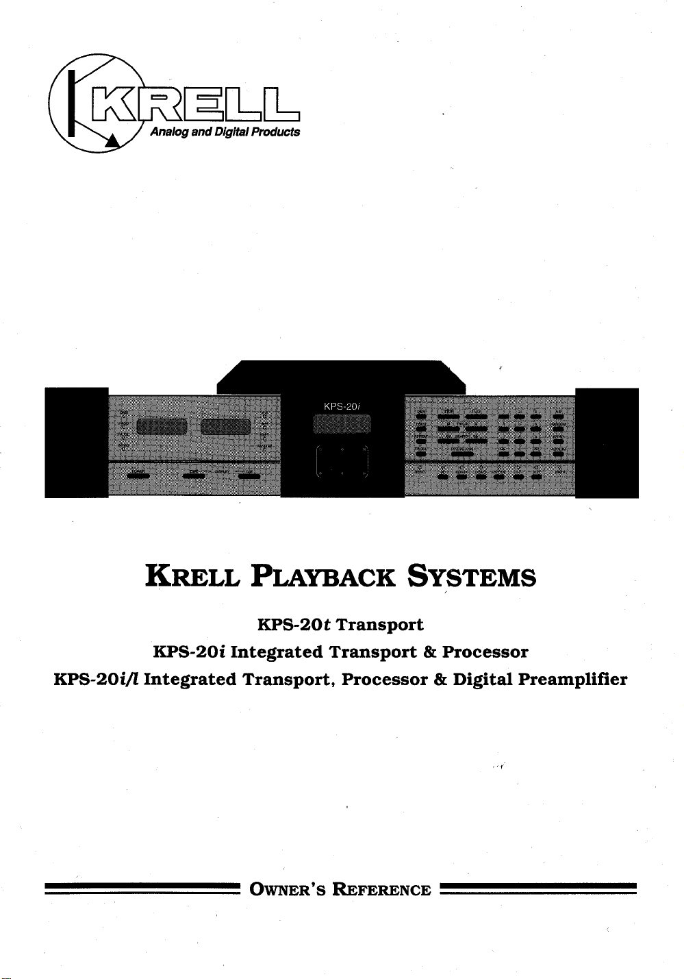
KRELL PLAYBACK SYSTEMS
KPS-20t Transport
KPS-20i Integrated Transport & Processor
KPS-20i//Integrated Transport, Processor & Digital Preamplifier
OWNER’S REFERENCE
Page 2
2
INTRODUCTION
4
UNPACKING AND PLACEMENT
5
GENERAL DESCRIPTION OF KPS-20 SERIES OWNER’S REFERENCE
AC POWER GUIDELINES
6
KPS-20 SERIES FRONT AND REAR VIEW
7
KPS-20 BASIC OPERATION
COMPLETE TRANSPORT FEATURES AND FUNCTIONS
8
TABLE OF CONTENTS
13
15
16
16
18
19
22
24
25
26
27
KPS-20i AND KPS-201//DETAILS
KPS-20i//VOLUME CONTROL
KPS-20t DETAILS
TRANSPORT TO PROCESSOR INTERLINK CONSIDERATIONS
TIME SYNC
REMOTE CONTROL
QUESTIONS AND ANSWERS
KPS-20i TYPICAL SYSTEM SETUP
KPS-20i//TYPICAL SYSTEM SETUP
KPS-20t TYPICAL SYSTEM SETUP
SPECIFICATIONS ’~
~
28
WARRANTY AND SERVICE
Page 3
INTRODUCTION
Thank you for your purchase of the KRELL PLAYBACK SYSTEM-20 series
component. Influenced by KRELL Reference and Audio Standard Series
componets, the KRELL PLAYBACK SYSTEM-20’s incorporate the latest
developments in Krell technology. Their advanced digital reconstruction
system, input and output connection capabilities, ergonomics, and stunning
aesthetics make the KRELL PLAYBACK SYSTEM-20 series an impressive
statement of audio technology.
KRELL PLAYBACK SYSTEM-20 (KPS-20) series components utilize a top load
design based on a high performance Philips transport mechanism. The
transport is housed in a solid machined block of brass and independently
suspended from the chassis by low-stored-energy isolation mounts. The main
chassis provides the first line of shock energy isolation with its own series of
low-stored-energy suspension mounts, leaving the inertially massive brass
laser chassis to dissipate any residual energy before it can influence the
tracking of the laser. Krell-written micro-code controls all transport functions
and input selections through a custom user interface. This interface is written
with performance and user flexibility as key design goals. Disc stabilization is
accomplished with a custom five point magnetic clamp and proprietary hub
alignment. The heavy motorized cover assembly isolates the compact disc from
ambient light. During playback the underside of the CD is bathed in green
light. This particular light spectrum increases the signal-to-noise of the laser’s
photo-diode which, in turn, increases its reading accuracy.
The KRELL PLAYBACK SYSTEM-20t comes standard with all current digital
output formats: ST fiber optic, AES/EBU balanced, SPDIF coaxial, EIAJ optical
and KRELL Time Sync.
In the KPS-20i and KPS-20i/I the identical transport mechanism is coupled to
an upgradeable software based processor. Data is transferred through custom
filter algorithms performing KRELL written reconstructive software at a 16X
oversampling rate through a Motorola DSP-56002 processor running at 66 MHz.
The 24 bit data is then fed to four differentially configured Burr Brown 20-bit
Colinear DAC’s.
2
Page 4
All critical circuitry utilizes four layer glass epoxy circuit boards. With its 100 VA
power supply and 11 independent stages of regulation, the power supply of the
KRELL PLAYBACK SYSTEM-20 is a rock solid source of pure current and
voltage for the digital and Class A analog output stages. The output stage is
classic KRELL. All output circuits are DC coupled, Class A and complementary.
The output stage has 18 volt rails and fully differential balanced outputs on gold
plated, berrylium copper XLR connectors. Single-ended outputs are also
provided via custom gold plated RCA connectors.
In the KRELL PLAYBACK SYSTEM-20i/I the high level output stage of the
KPS-20i is replaced with a line level output stage and volume control simfliar to
that of the KRELL KRC-2 preamplifier. This stage is optimized to drive the input
of a power amplifier directly.
The KPS-20i and KPS-20i/I support all major digital input formats: one ST fiber
optic, one AES/EBU balanced, two SPDIF coaxial, and one EIAJ optical. They
come standard with an SPDIF coaxial digital output. ST, EIAJ, and KRELL Time
Sync outputs are available as an option. All input switching is accessible from the
front panel or the remote control. KRELL’s proprietary Data Recovery and Jitter
Rejection Module recovers all data from external sources, reducing jitter to
exceptionally low levels.
This Owner’s Reference is intended to guide the clear, trouble free installation
and operation of your KRELL PLAYBACK SYSTEM-20. Should you have any
questions or comments, please feel free to contact your authorized dealer or the
KRELL staff for assistance.
In the unlikely event that your KRELL PLAYBACK SYSTEM-20 should require
service, you will be pleased to know that it is backed by a comprehensive
Customer Satisfaction policy and one of the most advanced service facilities in
the industry. For detailed information on the terms and conditions of service,
please consult the Warranty and Service section of this Reference, Warranty
Registration Card, or an authorized KRELL Dealer/Distributor.
3
Page 5
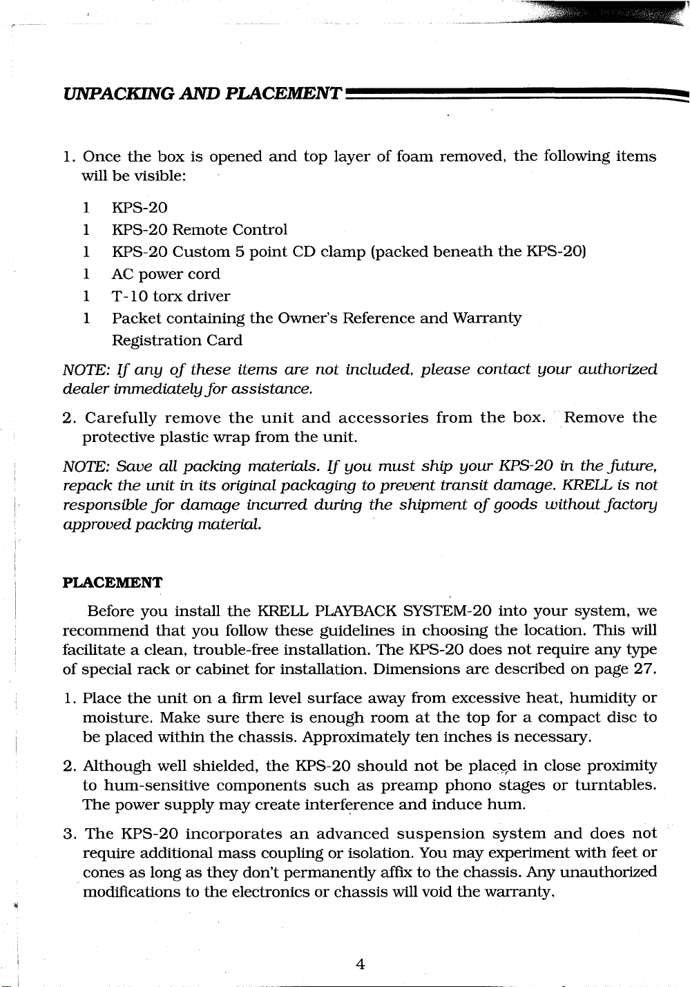
UNPACKING AND PLACEMENT
1. Once the box is opened and top layer of foam removed, the following items
will be visible:
1 KPS-20
1 KPS-20 Remote Control
1
KPS-20 Custom 5 point CD clamp (packed beneath the KPS-20)
AC power cord
1
1
T-10 torx driver
1
Packet containing the Owner’s Reference and Warranty
Registration Card
NOTE: If any of these items are not included, please contact your authorized
dealer immediately for assistance.
2. Carefully remove the unit and accessories from the box. Remove the
protective plastic wrap from the unit.
NOTE: Save all packing materials. If you must ship your KPS-20 in the future,
repack the unit in its original packaging to prevent transit damage. KRELL is not
responsible for damage incurred during the shipment of goods without factory
approved packing material.
PLACEMENT
Before you install the KRELL PLAYBACK SYSTEM-20 into your system, we
recommend that you follow these guidelines in choosing the location. This will
facilitate a clean, trouble-free installation. The KPS-20 does not require any type
of special rack or cabinet for installation. Dimensions are described on page 27.
1. Place the unit on a firm level surface away from excessive heat, humidity or
moisture. Make sure there is enough room at the top for a compact disc to
be placed within the chassis. Approximately ten inches is necessary.
2. Although well shielded, the KPS-20 should not be place~d in close proximity
to hum-sensitive components such as preamp phono stages or turntables.
The power supply may create interference and induce hum.
3. The KPS-20 incorporates an advanced suspension system and does not
require additional mass coupling or isolation. You may experiment with feet or
cones as long as they don’t permanently affix to the chassis. Any unauthorized
modifications to the electronics or chassis will void the warranty.
4
Page 6
GENERAL DESCRIPTION OF KPS-20 SERIF_~ OWNER’S REFERENCE
The features, functions and operation of the transport are identical for all
three KPS-20 Series products. Descriptions of them are divided into two
sections: Basic Operation provides a quick installation procedure; Complete
Transport Features and Functions provides details on all KPS-20 transport
capabilities. Features specific to the KPS-20i, KPS-20i// and KPS-20t are
described on pages 13, 15 and 16 respectively.
As with all sophisticated products, a complete reading of this Owner’s
Reference will provide thorough understanding of the KPS-20 Series products.
Please contact your authorized dealer, distributor or the factory if you have any
questions not addressed by this Reference.
IMPORTANT NOTE: The use of CD rings, mats, or other devices attached to
individual CDs is not recommended. To be completely effective, the KPS-20 clamp
must make direct contact with the CD. Otherwise, erratic playback and~or poor
sound may occur
AC POWER GUIDELINES
The KPS-20 has superb regulation and does not require a dedicated AC
circuit. We strongly advise against connections through extension cords or
multiple AC adapters. High quality 15 amp grounded AC strips are acceptable.
High quality AC line conditioners or filters can be utilized if they are grounded
and meet or exceed the unit’s Power Supply rating of 100VA.
CAUTION: Do not remove or bypass the ground pin on the end of the AC cord.
This may cause RFI (radio frequency interference) to be induced into your
playback system.
5
Page 7
KPS-20 SERIES
FaONT vii w
KPS-20i/I
@ ®
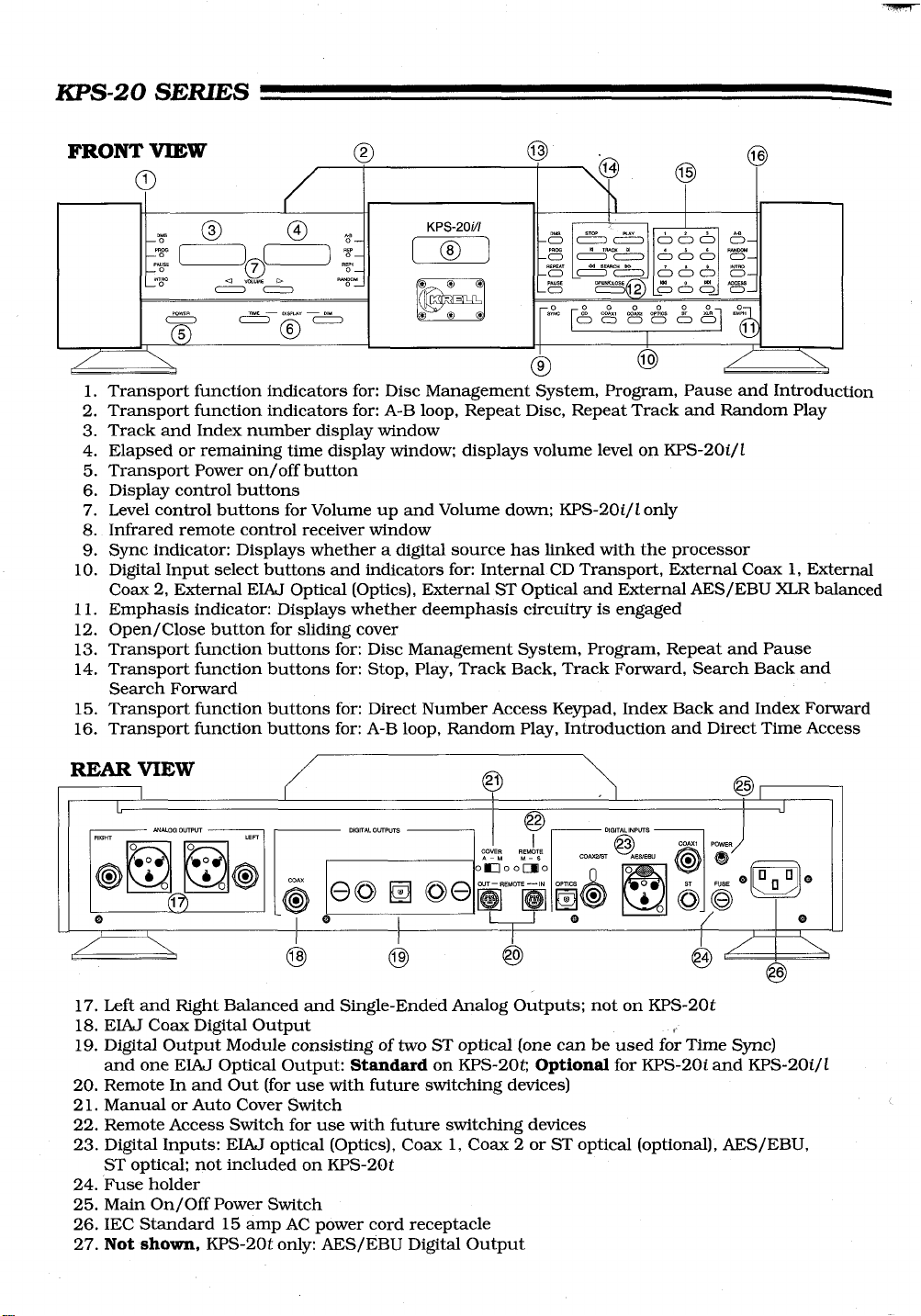
1. Transport function indicators for: Disc Management System, Program, Pause and Introduction
2. Transport function indicators for: A-B loop, Repeat Disc, Repeat Track and Random Play
3. Track and Index number display window
4. Elapsed or remaining time display window; displays volume level on KPS-20i/I
5. Transport Power on/off button
6. Display control buttons
7. Level control buttons for Volume up and Volume down; KPS-20i/I only
8. Infrared remote control receiver window
9. Sync indicator: Displays whether a digital source has linked with the processor
Digital Input select buttons and indicators for: Internal CD Transport, External Coax 1, External
10.
Coax 2, External EIAJ Optical (Optics), External ST Optical and External AES/EBU XLR balanced
11. Emphasis indicator: Displays whether deemphasis circuitry is engaged
Open/Close button for sliding cover
12.
Transport function buttons for: Disc Management System, Program, Repeat and Pause
13.
Transport function buttons for: Stop, Play, Track Back, Track Forward, Search Back and
14.
Search Forward
Transport function buttons for: Direct Number Access Keypad, Index Back and Index Forward
15.
Transport function buttons for: A-B loop, Random Play, Introduction and Direct Time Access
16.
REAR VIEWI
@l
@ @ @ @
17.
Left and Right Balanced and Single-Ended Analog Outputs; not on KPS-20t
18.
EIA~J Coax Digital Output ,
19.
Digital Output Module consisting of two ST optical (one can be used for Time Sync)
and one EIAJ Optical Output: Sta~daJrd on KPS-20t;, Optional for KPS-20i and KPS-20i/I
20.
Remote In and Out (for use with future switching devices)
Manual or Auto Cover Switch
21.
22.
Remote Access Switch for use with future switching devices
23.
Digital Inputs: EIAJ optical (Optics), Coax 1, Coax 2 or ST optical (optional), AES/EBU,
ST optical; not included on KPS-20t
24.
Fuse holder
25.
Main On/Off Power Switch
IEC Standard 15 amp AC power cord receptacle
26.
27.
Not shown, KPS-20t only: AES/EBU Digital Output
Page 8
KPS-20 BASIC OPERATION
Below are instructions for a quick installation of the KPS-20. Please refer to
the Typical System Setup illustrations on pages 24, 25, and 26. Also, allow the
unit to settle at room temperature before operation is started.
1. Plug the KPS-20 into the standard wall AC receptacle. Connect the KPS-20
output to the appropriate location: KPS-20i to preamp input; KPS-20i/I to
amplifier or crossover input; KPS-20t to D/A processor input. Engage the
power switch on the rear panel by pushing it up to the ON position. This
powers the processor sections in the KPS-20i and KPS-20i/I.
2. Press the Power button on the front panel or on the remote control to power
the transport stages. The display section will now illuminate. The processor
portion of the KPS-20i and KPS-20i/I is on at all times once the rear panel
switch is engaged. This is to insure thermal stability and improve sonic
performance.
Press the Open/Close button on the front panel and the top cover assembly
3.
will open, exposing the CD transport and spindle. Place the compact disc,
label side up, onto the drive spindle. Place the five point custom clamp onto
the drive spindle, securing the CD in place. Make sure the clamp is centered
firmly on the custom CD spindle hub. Press the Open/Close button again or
Play and the cover will close.
NOTE: In the event that you wish to rapidly change a number of CDs, the
KPS-20 can be played with the cover open. Move the switch on the back panel
marked "Manual~Auto" to the "Manual" position..The KPS-20 will now play
with the cover open. However, do not forget that you are compromising the
quality of the music when the CD is exposed to light. Also, it is always
preferable to close the cover when playing music at a high volume in order to
maintain optimum tracking.
4. Press Play on the front panel or remote control. Note: if you pressed Play in
step 3 the disc will already be playing. The disc will start playing from track 1.
To select a ’different track you can press the track forward {> I} or track back
{I <} button until you reach the desired track number or punch the number of
the desired track into the keypad on the front panel or rem’ote control.
5. Press the Stop button to stop play.
7
Page 9
COMPLETE TRANSPORT FEATURES AND FUNCTIONS
The KPS-20 has a wide variety of transport functions. New capabilities have
been added to standard functions to enhance the use of the KPS-20, Listed below
are the functions which can be accessed from the front panel and remote control.
STOP: Stops the disc while playing. Erases all short term program memory.
Does not erase Disc Management System (DMS) data.
PI~Y: Starts the disc playing from track 1 or from a keypad-selected track.
Begins standard track programming. Pressing the Play button during a track
will start that track again from the beginning.
I<: Track Back. Selects and begins playing the track previous to the current
track. Also scrolls backward through DMS or standard track programming.
> I : Track Forward. Selects and begins playing the track after the current track.
Also scrolls forward through DMS or standard track programming.
I< I<: INDEX Back. Selects the index number previous to the current index
number within a specific track if the CD was recorded with separate indexing.
> I > I : INDEX Forward. Selects the next index number within the current track
if the CD was recorded with separate indexing.
NOTE: Some discs do not have index numbers programmed within tracks. When
the Index buttons are pressed the display will default to the current track
number.
<<: Search Back. Fast scroll backward through program.
NOTE: When operating in Search Back the system searches in 5 second increments.
>>: Search Forward. Fast scroll forward through program.
PAUSE: Temporarily stops play of current track. Does not effect DMS or
standard track programming. Second press of the Pause button resumes play.
REPEAT: (REP and REP 1) When pressed once, repeats the entire disc, DMS
standard track program indefinitely. When pressed twice, will continuously
repeat only the current track. Press Stop or Repeat a third time to cancel this
function. When selecting the Repeat function desired, press the.~Repeat button
once and the LED indicator on the faceplate will illuminate. Press the Repeat
function twice and the REP 1 indicator LED will illuminate, indicating only a
single track will repeat.
8
Page 10

0-9 NUMBERED KEYPAD: The direct access keypad makes track selection
quick and easy. When using the direct track access function, the selected
track will begin play immediately after a one or two o.digit number is selected.
Select the number of your choice directly or follow the program selection
sequence if writing a program..
RANDOM: Will play tracks in a non-selected order. Press the Random button
and the disc will begin play in a sequence other than the original. Press again
and another randomly selected track will play. Press Stop to exit the Random
play mode.
INTRO: Plays a 20 second sample of each track on the disc. Press the Stop
button to resume normal play.
DISPLAY: Toggles between the time into the current track and the amount of
total disc time remaining.
DIM: Shuts off the display and function LEDs. Second press activates the
display and function LEDs.
A/B: The KPS-20 can make a loop between two pre-determined points within a
track. This is helpful when you need to repeat a specific segment of a track.
How to Create an A/B Loop:
Start play of track. When you hear the part that you want as the beginning of
the loop press A/B to insert the start position. Press A/B again to insert finish
position. A/B play will automatically begin and continue indefinitely. Press
Stop or A/B again to delete the A/B program.
ACCESS: The Access function gives you the ability to numerically select a
position within a specific track program. This is valuable when exact start
positions are critical.
9
Page 11

COMPLETE TRANSPORT FEATURES AND FUNCTIONS -
How to Gain Access to a Specific Time in a Track:
1. Press Access. Two zeros will show on the display.
2. Enter a one or two digit track number, then press Program.
3. Enter a one or two digit minute number, then press Program.
4. Enter a one or two digit second number, then press Program. The track will
immediately begin play at the designated time.
EXAMPLE: Here is a program to begin play at Track 2, 1 minute and 1 1
seconds into the piece.
1.
Press Access
2.
Press 2 then Program
3. Press 1 then Program
4. Press 11 then Program
NOTE: When entering an access number, remember not to exceed the track’s
playing time while programming. When this occurs your access number will not
be acknowledged.
PROGRAM/PROG on Remote: Standard track programming gives you the
ability to select which tracks you would like to hear and the order in which you
would like to hear them. This method of programming is short term and will be
cleared when you press the Stop button. Once a program is written, basic
functions like Pause, Repeat, Track forward, and Track Back work within the
program. The program will be cleared from memory once the last programmed
track is played or the Stop button is depressed. The program will continually
play if the Repeat button is depressed. To temporarily stop play within a
program, press the Pause button. Remember, Stop will erase the program.
SPECIAL NOTE: If you get confused with the sequence while in the middle of
programming, press the Stop button and start again. This will clear all
programming in temporary memory.
HOW TO WRITE A PROGRAM
1. Press the Program button on the front panel or remote control. The Program
LED will be illuminated next to the display. This puts the machine in
Program mode.
10
Page 12

2. Select the track you want first in the program. You can use the Track
Advance and Reverse buttons to select the track numbers or punch the
number directly into the keypad.
After you select the track, press the Program button again. The track you
3.
selected is now in program memory.
4. Repeat this sequence for each track you want in your program.
EXAMPLE: Here is a sample program sequence
1. Press Program
2. Press 2, then Program
3. Press 4, then Program
4. Press 6, then Program
5. Press 8, then Program
Press Play and the program sequence 2, 4, 6, 8, will begin.
NOTE: While playing the program, the Track Forward, Track Back, Repeat, and
Pause functions work within the program.
To clear the program memory press the STOP button.
DMS
The Disc Management System (DMS) allows a track program you have
written to be saved indefinitely in the KPS-20’s memory.
CAUTION: Please proceed slowly and follow the Sequence carefully while
learning to program DMS. The DMS function will appear to be malfunctioning if
the sequence is changed.
How to Write a DMS Program
1. Press the Program button on the front panel or remote control. The program
LED will be illuminated next to the display. This puts the machine in the
program mode.
2. Follow the standard program instructions as described above.
3. Once the Program is written, press the DMS button on the front panel or
remote control. Press the Program button and the DMS LED on the front
panel will illuminate. The DMS program is now complete.
11
Page 13

COMPLETE TRANSPORT FEATURES AND FUNCTIONS
EXAMPLE: Here is a sample DMS program sequence
1.
Press Program
2. Press 1 then press Program
3. Press 3 then press Program
4. Press 5 then press Program
5. Press 7 then press Program
6. Press DMS
7. Press Program
The DMS program is now entered into the KPS-20’s permanent memory. To
play the program, press DMS, then Play. The DMS program sequence 1, 3, 5, 7,
will begin.
How to PLAY a DMS Program
1. Insert the disc into the KPS-20.
2. Close the top cover. The DMS LED will illuminate indicating there is a DMS
programmed disc in the machine.
-
3. Press the DMS button on tile front panel or remote control.
4. Press Play. The Program LED on the front panel will illuminate and the DMS
program will begin.
NOTE: If the Program LED is not illuminated, the KPS-20 has not recognized the
DMS program and will play the disc in the normal way.
How to Erase a DMS Program
Once the disc is enclosed in the KPS-20 and the DMS program LED is illuminated,
press the DMS button and immediately press the Stop Button. The DMS LED
will extinguish, indicating the DMS program is erased.
12
Page 14

KPS-20i AND KPS-20i/I DETAILS
This is a description of the additional features and functions common to the
KPS-20i and KPS-20i/I. Please contact your KRELL dealer or the KRELL staff
for assistance if there are any questions not covered~in this Reference. Please
refer to the KPS-20i and KPS-20i/I Typical System Setups illustrations on
pages 24 and 25.
CAUTION: When making connections to this component or any other, make sure
the power amplifier is OFF and the preamplifier is in the MUTE or STANDBY
mode.
ANALOG OUTPUT CONNECTIONS
The KPS-20i and KPS-20i/I are equipped with two analog output
configurations: Single-ended via RCA connectors and balanced via XLR
connectors. If your preamplifier has high level balanced inputs, we recommend
the balanced outputs be used. There are considerable sonic benefits to be
gained with use of the balanced format.
The XLR pin configuration is described below.
Pin 1
Pin 2 Non-inverting (0
Pin 3
The left and right channel RCA and balanced outputs are labeled on the back
panel. Care should be taken that the correct left/right orientation is
maintained.
NOTE: These two outputs can be used to simultaneously feed different systems.
EMPHASIS LED
Emphasis is part of an encode/decode recording technique. Discs and/or
tracks that were recorded with this process will cause the Emphasis LED to
illuminate. When the Emphasis LED is lit the appropriate circuitry is activated
to provide fiat frequency response. ~
Ground
°)
°)
Inverting ( 180
13
Page 15

KPS-20i AND KPS-20i/1 DETAILS
DIGITAL SOURCE TO KPS-20i INTERLINK CONSIDERATIONS
Care should be taken in selecting the type of cable used to link a digital
component to the KPS-20i or KPS-20i/I. Although the KPS-20 series will accept
all industry standard formats, we suggest using the ST wide bandwidth format.
Refer to the KPS-20i Typical System Setup on page 24.
DIGITAL INPUT CONNECTIONS
The KPS-20i and KPS-20i/I come standard with most current digital input
formats: ST fiber optic, AES/EBU balanced, EIAJ fiber optic, and two SPDIF
coaxial inputs.
Connect the sources’ digital output(s) to one of the digital inputs on the
KPS-20i or KPS-20i/I. When the corresponding input of the desired digital
source (must be ON) is selected, the appropriate input indicator LED will
illuminate. The Sync LED will then illuminate, indicating the digital source and
internal processor have linked. The Processor automatically selects the correct
input frequency for the source.
DIGITAL OUTPUTS
The KPS-20i comes standard with one coaxial digital output. Signal from the
input selected on the front panel or remote is routed to this output for sending
to a digital recording device or external D/A processor.
An optional Digital Output Module is available to provide additional outputs in
ST optical and EIAJ optical formats. Also included is a second ST output that
can be internally switched between the normal digital output and Krell’s
proprietary Time Sync system. Please refer to pages 16 through 18 for more
information about the connection of digital outputs and Time Sync.
14
Page 16

KPS-20i/I VOLUME CONTROL
All input and output connections for the KPS-20i/I are identical to those for
the KPS-20i, with the exception that the KPS-20i/I analog outputs connect
directly to the inputs of a power amplifier or crossover. Please review the
KPS-20i/I Typical System Connection Diagram on page 25.
Operation of the KPS-20i/I is identical to the KPS-20i with the exception of the
volume control. The operation on the volume control and associated display are
detailed below.
VOLUME CONTROL
The KPS-20i/I utilizes a discrete ladder network volume control. When volume
Up or Down is selected via the front panel or the remote control, the numeric
display will provide a 0--158 step indication of the volume level. The level
position will remain on the display for a few seconds and then return to the
transport display mode.
To adjust listening level hold down either the volume Up or Down button. The
volume will begin increasing or decreasing in one step increments. After a short
time, the volume will begin changing in larger, multi-step increments. This is
intentional and allows for more rapid changes in volume adjustment.
To check your volume level without changing the level, briefly depress either
the volume Up or Down button. The display will show your present volume level
for a short time before returning to the transport display mode.
CAUTION: Do not connect the output of the KPS-20i/I to ~the input of a preamplifier
The KPS-20i/I output is designed for connection directly to the input of an amplifier
and may damage a preamplifier input.
15
Page 17

KPS-20t DETAILS
All operational features and functions of the KPS-20t are described on pages
7 through 12 of the Reference. Detailed below are various issues related to the
connection of the digital outputs. This information is also valid for the KPS-20i
and KPS-20i/I if the optional Digital Output Module is installed. Please refer to
the KPS-20t Typical System Setup on page 26 for a detailed view of how the
KPS-20t is installed in an audio system.
CAUTION: When making connections to this component or any other, make sure
the power amplifier is OFF and the preamplifier is in the MUTE or STANDBY mode.
DIGITAL OUTPUT CONNECTIONS
The KPS-20t comes standard with all current digital output formats:
ST fiber optic, AES/EBU balanced, SPDIF coaxial, EIAJ optical and KRELL
Time Sync.
Connect the digital output(s) of the KPS-20t to the input(s) of a digital recording
device and/or digital-to-analog processor.
The KPS-20t is also fitted with Time Sync. Time Sync is a proprietary system
that locks the clocks of the transport and certain KRELL processors. For a
complete description of Time Sync, see page 18.
If you are using the Time Sync option, connect an ST cable between the KPS-20t
Time Sync output and Time Sync input on a Krell processor.
For specific instructions on connecting ST cables refer to page 17.
TRANSPORT TO PROCESSOR INTERLINK CONSIDERATIONS
Care should be taken in selecting the type of cable used to link your
KPS-20t and processor. We suggest using the ST wide bandwidth fiber optic
format. This format has a data rate of approximately 50 megabit. This allows
accurate transmission of the digital bit stream without data corruption and
proves to be sonically superior. Using a fiber optic interconnect also reduces
ground loop problems often associated with quality audio systems.
If coaxial cable is used, it should be non-capacitive and have a bandwidth in
excess of 10 MHz to prevent drop-out errors. For best results with coaxial cable
we recommend the AES/EBU balanced format. The AES/EBU format is a _+ 5 volt
balanced digital transmission. Because of the high voltage balanced format, this
system allows for accurate data transmission and has great sonic advantages
over standard single-ended coaxial or EIAJ fiber optic formats. The AES/EBU
coaxial cable must have two conductors and a shield for balanced termination.
16
Page 18

HOW TO CONNECT ST CABLES
1. Remove the plastic cover from the outside of the ST transmitter (located on
transport) and receiver (located on processor).
2. Remove the plastic cap from both ends of the ST cable.
3. Locate the key tab on the end of the ST cable.
4. Locate the slot on the top of the ST receptacle.
5. Slide the cable connector into the ST receptacle, with the key guided into the
designated slot.
6. Gently push the connector into place, depress the internal spring, and twist
the outer collar clockwise to secure the outer ring to the posts on the chassis
connector.
7. Use the same procedure for the processor input.
ST/TIME SYNC OUTPUT
The ST connector labeled ST/Time Sync can be switched between Time
Sync and a normal data output. The KPS-20t comes with this output Set for
Time Sync. Follow the procedure below to switch it to a data output:
1. Turn the power amplifier Off and the preamplifier to Mute or Standby
2. Turn the two thumbscrews counterclockwise until they release from the
chassis
Hold the thumbscrews and pull the panel/board assembly straight out of the
3.
unit
4. On the circuit board there is a switch labeled Time Sync on one side, Data
on the other
5. Move the switch to the Data
6. Slide the board back into the chassis
7. Firmly press the board into its mating connector
Turn the thumbscrews clockwise until they are tight
8.
17
Page 19

TIME SYNC
TIME SYNC
Time Sync is an independent clock data transfer system that was developed
to eliminate recovery jitter. Time Sync couples the high speed master clock
output from the transport directly to the processor. This means there is one
system master clock for the transport and processor. The use of the Time Sync
system requires that a KRELL processor be equipped with a Time Sync input.
It also requires that the Time Sync output of the KPS-20t be connected to the
Time Sync input of the processor using an ST fiber optic cable.
With Time Sync operating, the processor does not use a recovered clock
generated by its decoder. Instead, the transport’s clock feeds the input of the
DACs. This process climates 100% of the jitter corruption inherent in all clock
recovery type systems. The ST interface was chosen for its high data rate and
its immunity to radiated R.F. and 60 cycle noise corruption.
Refer to the KRELL D/A Processor’s Owner’s Reference for Time Sync operating
instructions.
18
Page 20

REMOTE CONTROL
REMOTE CONTROL OPERATION
The KPS-20 comes equipped with a universal remote control from which
basic preamp, amplifier, processor, and complete transport functions can be
controlled. A brief description of the buttons and their functions is provided. A
diagram of the remote control is provided on page 21. All KPS-20 functions can
be controlled from the front panel or the remote control. Basic preamp and
amplifier functions are listed below.
REMOTE ONLY FUNCTIONS
(AMP) POWER: Turns KRELL Audio Standard or S-Series amplifiers On or Off.
(AMP) METER: Turns KRELL S-Series amplifiers bias level meters On or Off
and cycles through KRELL Audio Standard meter functions.
There are three buttons on the face of the remote control marked PLAYER,
PREAMP, and D/A. These buttons determine which type of KRELL component
the remote control will address. When one of these function buttons is selected,
the LED directly above that button will flash. These buttons affect only the
functions beneath them.
PLAYER: When engaged, the remote control addresses a KRELL CD Player.
Control of digital input selection is available for the KPS-20i and KPS-20i/I.
Control of volume and mute are available for the KPS-20i/I.
PREAMP: When engaged, the remote control addresse~ a KRELL remote control
preamplifier. Control of Volume, Phase, Input Select, and Mute are accessible
from the remote control.
D/A: When engaged, the remote control will address future KRELL processors.
This button is not used for the KPS-20 Series.
19
Page 21

REMOTE CONTROL
BATTERY INSTALLATION AND REMOVAL
NOTE: Batteries should be replaced when functions from the remote control
become intermittent. The KPS-20 universal remote uses two AAA size 1.5 volt
batteries.
1. With the T-10 torx driver remove the four screws from the remote control
back plate.
2. Remove the back plate to expose the batteries.
3. Remove the old batteries and install new ones, following the battery position
diagram on the plastic battery receptacle.
4. Re-install the back plate and four screws.
5. Check to make sure the remote control is functioning properly.
6. Tighten the four back plate screws.
If you have questions about the remote control operation contact the KRELL
staff for assistance.
2O
Page 22

IIIII I II I I III III Ill II
I II II
Power\ (.
access
keypad
Pause~ PAUSE 0
Stop ~~
Cover open ~ ~STO~ P~Y
Track back~
Search fo~ard <a
Search back~ ~
Index back~ ~
Loop inse~ion
Display change~ ~
Brief introduction ~ ~
of track samples
CD player select ~ -- ~
Preamp or KPS-20i/I volume down
Preamp, KPS-20i or
20i/I input select
Preamp phase reverse
\|
C~,~ f-~ AMP
IPOWER
~ T~CK
DISPLAY ~B ACCESS
~o ~OM
~
NO o o
P~YER PREAMP D/A
-~~-
~ VOLUME
INPUT/PHASE MUTE
Amplifier meter display
Amplifier power
Repeat
,, / Play
/ Track forward
/ Program
/ Index forward
~ Disc Management Sys.tem
/ Direct access
/ Display dim
Random track play
select
select
~ Preamp or KPS-20i/I volume up
"~- Preamp or KPS-20i/I mute
2]
Page 23

QUESTIONS AND ANSWERS
Qo
My CD transport has both fiber optic and coaxial outputs. Which one
should I use?
Given a choice, we prefer the ST format due to its complete isolation of the
grounds between digital source and processor. This minimizes the
possibility of ground loops in the digital components. The ST format also
has the added benefit of substantially higher bandwidth than coaxial or the
standard fiber optic interface. If a coaxial cable must be used, we suggest
the AES/EBU balanced format. This format utilizes a -+ 5v digital format
and has the additional benefit of balanced termination.
Qo
Will I damage my KPS-20 if I leave the power ON all the time?
No it’s intended to be on at all times. The circuits perform more consistently
once they reach thermal equilibrium.
NOTE: For the protection of your unit, we recommend disconnecting the AC
cord from the wall outlet before any electrical storms or if you plan on being
away from home for prolonged periods of time.
Qo
I have some very fine audiophile interconnect cable which has superior
sonic characteristics. Can I use this for my coaxial digital input?
You may experiment with any high quality cable. Note that most audio
interconnect cable is not designed to carry the ultra-high frequency
information of the digital bit stream.
NOTE: For the KPS-20, we recommend non-capaditive coaxial cable which has
a bandwidth in excess of I OMHz and excellent shielding properties. This is
true on both RCA and XLR terminated cables.
When I try to play a certain disc the KPS-20 displays an error message and
will not play. Is the transport defective?
Ao
Check to make sure the magnetic clamp is properly centered on the disc. If
this is not the problem, the disc may need to be cleaned. If the surface of
the disc is soiled the laser cannot read the data and ~will display an error
message or skip sections of tracks. You may want to experiment with some
of the compact disc cleaning products. If after cleaning the disc, it still will
not play, the problem may be with the indexing on the CD. Some recording
companies stretch the parameters of the CD, preventing them from
22
Page 24

KPS-20i TYPICAL SYSTEM SETUP
LOUDSPEAKERS
KSA AMPLIFIER
Digital components can
connect to different inputs
than are shown
SATELLITE RECEIVER
CABLE DIGITAL RADIO RECEIVER(DMX)
PREAMPLIFIER
IR L
OUTPUT
KPS-20i
~-~ DAT DECK
24
Page 25

Digital components can
connect to different inputs
than are shown
KPS-20i/I TYPICAL SYSTEM SETUP
LOUDSPEAKERS
KSA AMPLIFIE
&
SATELLITE RECEIVER ~-~
CABLE DIGITAL RADIO RECEIVER(DMX)
KPS-20|
I
I
DAT DECK
25
Page 26

KPS-20t TYPICAL SYSTEM SETUP
~"~ KSA AMPLIFIER ~~
i
~~~ ,[]
~ ~
Different digital
s°~tpUownt Sc than~e a~:ed
~’ ~
R k
INPUT
t t
REFERENCE
PREAMPLIFIER
~R k
OUTPUT
TIME SYNC ST
KPS-20t
26
Page 27

SPECIFICATIONS
TRANSPORT:
Modified CDM-9 pro with hall effect motor, swing-arm design in a unicast
frame. Custom magnetic disc clamp.
LASER:
Single beam with a glass lens
TOP COVER:
Gear driven mechanism; auto or manual control
CONTROL FUNCTIONS:
KRELL written keypad processing software
KPS-20i and KPS-201//ANALOG OUTPUTS:
Balanced via XLR connectors
Single-ended via RCA connectors
KPS-20t DIGITAL OUTPUTS:
ST Optical, EIAj Optical, AES/EBU balanced, S/PDIF coax
2nd ST Optical switchable between data and Krell Time Sync
KPS-20i and KPS-20i//DIGITAL OUTPUTS:
S/PDIF coax
KPS-20i and KPS-20i//DIGITAL OUTPUT MODULE OPTION:
ST Optical, EIAJ optical, 2nd ST Optical switchable between data
and Krell Time Sync
KPS-201 and KPS-20i//DIGITAL INPUTS:
ST Optical, EIAJ Optical, AES/EBU balanced, two S/PDIF coax
Note: 2nd coax input can befitted with ST format optical on request
REMOTE CONTROL:
Multi-function wireless infrared with additional control of Krell amplifiers
and preamplifiers
WEIGHT:
Unit weight: 36 lbs.
Boxed weight: 50 lbs. ,~
DIMENSIONS:
19" W x 14.5" D x 4.75" H
All operational features, functions, and specifications and policies are subject to change
without notification.
27
Page 28

WARRANTY AND SERVICE
THERE ARE NO USER-SERVICEABLE PARTS INSIDE ANY KRELL PRODUCT.
KRELL PLAYBACK SYSTEM-20 has a limited and transferable warranty of five
years for parts and labor and three years on trahsport related parts. The
warranty period begins on the date of retail purchase,’ as noted on the retail
sales slip provided by an authorized KRELL Dealer or Distributor, or on the
warranty registration card sent to KRELL. In the event adequate proof of
purchase date is unavailable, the warranty period will begin on the date the
unit was originally shipped from the factory. The original ship date can be
determined by KRELL from the serial number.
The warranty for KRELL products is valid only in the country to which they
were originally shipped, through the authorized KRELL Distributor for that
country, and at the factory. There may be restrictions on, or changes to
KRELL’s warranty because of regulations within a specific country. Please
check with your Distributor for a complete understanding of the warranty in
your country.
Freight to the factory is your responsibility. Second day return freight within
the United States is included in the warranty. If you have purchased your
KRELL product outside the United States and wish to have it serviced at the
factory, all freight and associated charges to the factory are your responsibility.
Krell will pay return freight to the US-based freight forwarder of your choice.
Freight and other charges to ship the unit from the freight forwarder to you are
also your responsibility.
The operating voltage of this unit is determined by the factory and can only be
changed by an authorized KRELL Distributor or at the factory. The voltage for
the KRELL PLAYBACK SYSTEM-20i in the USA can not be changed until six
months from the original purchase date. Any unauthorized voltage conversion,
disassembly, component replacement, perforation of chassis, updates, or
modifications performed to the unit will void the warranty.
KRELL is not responsible for any damage incurred in transit. KRELL will file
claims for damages as necessary for units damaged in transit to the factory.
You are responsible to file claims for shipping damages during the return
shipment.
28
~
~
Page 29

The use of any packing material other than original is not recommended.
KRELL may, at its discretion, pack a unit in new packing for the return
shipment and bill you for such packing if the unit was packed in non-standard
packing or the original packing is so damaged as to be unusable. Should you
need to purchase additional packaging please contact your authorized KRELL
Dealer, Distributor or KRELL for assistance.
IMPORTANT: If you think there are problems with your unit, please contact your
Dealer, Distributor, or the factory immediately. Do not return any unit to KRELL
for repair without first calling to discuss the problem and to obtain a Return
Authorization number.
All operational features, functions, and specifications and policies are subject
to change without notification.
29
Page 30

KRELL
45 Connair Road ¯ Orange, CT 06477
203’799-9954 ¯ Fax: 203-799-9796
Copyright 1995 KRELL
P/N D960601600000
 Loading...