


KCT
Krell Current Tunnel
CAST Preamplifier
Instructions for Use
Owner’s Reference
THE LEADER IN AUDIO ENGINEERING

KCT
Krell Current Tunnel
CAST Preamplifier
v 01.0
Krell Industries, Inc.
45 Connair Road
Orange, CT 06477-3650 USA
TEL 203-799-9954
FAX 203-891-2028
E-MAIL krell@krellonline.com
WEBSITE http://www.krellonline.com
This product is manufactured in the United States of America. Krell ® is a registered trademark of Krell Industries, Inc., and is restricted for use by Krell
Industries, Inc., its subsidiaries, and authorized agents. Sustained Plateau Bias III™ is a trademark of Krell Industries, Inc. and is a Krell technology based
on U.S. Patent No. 5,331,291. CAST™, CAST II™, Krell Current Mode™, Krell Link™, and Theater Throughput™ are trademarks of Krell Industries, Inc.
All other trademarks and tradenames are registered to their respective companies.
© 2000 by Krell Industries, Inc. All rights reserved P/N 304373
This product complies with the EMC directive (89/336/EEC) and the low-voltage directive (73/23/EEC).
WARNINGS
The preamplifier must be placed on a firm, level surface where it is not exposed to dripping or splashing.
The ventilation grids on the top of the preamplifier and the space underneath the preamplifier must be
unobstructed at all times during operation. Do not place flammable material above or beneath the preamplifier.
Before making connections to the preamplifier, ensure that the power is off and other components are in mute
or stand-by mode. Make sure all cable terminations are of the highest quality, free from frayed ends, short circuits, or cold solder joints.
Do not connect an RS-232 cable to the phono power port. Output from the phono power port could seriously
damage your computer. Do not connect the cable from a Krell KPE phono stage to the RS-232 port.
THERE ARE NO USER SERVICEABLE PARTS INSIDE THE PREAMPLIFIER
Please contact your authorized Krell dealer, distributor, or Krell if you have any questions not addressed in
this manual.

Contents Page
INTRODUCTION 1
DEFINITION OF TERMS 1
REVOLUTIONARY KRELL CAST TECHNOLOGY 3
UNPACKING 5
PLACEMENT 5
AC Power Guidelines 5
QUICK START 6
FRONT PANEL DESCRIPTION 9
BACK PANEL DESCRIPTION 12
REMOTE CONTROL DESCRIPTION 15
Battery Installation and Removal 15
CONNECTING THE KCT PREAMPLIFIER TO YOUR SYSTEM 18
Input and Output Connections 18
KRELL LINK CONNECTIONS AND OPERATION 19
TAPE INPUT AND OUTPUT 20
OPERATING THE KCT PREAMPLIFIER 21
On/Off and Stand-by Operation 21
Main Zone and Zone 2 Operation 22
TROUBLESHOOTING SYSTEM NOISE 25
CUSTOMIZING THE KCT PREAMPLIFIER 26
Z1 and Z2 Balance 26
Input Name Menu 26
Input Level Trim 27
Input Balance Trim 27
Theater (Throughput) Mode 28
Brightness 29
Mute Menu 29
Output Trigger Setup 29
Tape Output Menu 30
Krell Current Tunnel iii

Contents, continued Page
AC Mains Menu 30
Program Remote Menu 31
Input Trigger Setup 31
Setup Memory 32
Krell Link 32
Trigger Delay Setup 33
Exit Menu 33
QUESTIONS AND ANSWERS 34
WARRANTY 35
RETURN AUTHORIZATION PROCEDURE 36
SPECIFICATIONS 37
List of Illustrations
Figure 1 The KCT Front Panel 8
Figure 2 The KCT Back Panel 11
Figure 3 The KCT Remote Control 14
iv Krell Current Tunnel

Introduction
Thank you for your purchase of the Krell Current Tunnel (KCT) CAST Preamplifier. The
KCT features Krell Current Tunnel topology and Krell CAST technology, which work
together to reproduce music with unparalleled sound quality. The KCT has dual zone
capability for listening to music from different input devices at the same time, or listening
to one input device while recording another. Each zone has its own volume and balance
control.
Step-by-step menu options allow you to customize the KCT for ease of use and
seamless integration into your system. Remote control features include a handheld
remote control, which accesses all preamplifier functions as well as the compact disc
functions on Krell compact disc players. The KCT also features Krell Link, RS-232 and
12 VDC (12 Volt trigger) remote control inputs for a variety of system control options. A
menu-driven program remote option allows you to send KCT operating commands to a
learning or programmable remote control.
A front panel display provides feedback on input and zone status, menu function and
selection, and all preamplifier operations.
This owner’s reference manual contains important information on the placement,
installation, and operation of your KCT preamplifier. Please read this information
carefully. A thorough understanding of these details will help ensure satisfactory
operation and long life for your KCT and related system components.
Definition of Terms
Following are the definitions of key terms used in your owner’s reference manual.
CONFIGURATIONS
Krell Link
A method of synchronizing remote control operation for Krell systems that include
multiple preamplifiers, amplifiers, and associated components. When Krell Link in/out
connections are used, the remote capabilities of the linked components are controlled
from one component, called the control component. The linked components respond to
stand-by and operational mode commands from the control component via MIDI cables.
Theater Throughput
Theater Throughput is a Krell configuration option that allows the signal from a surround
preamp/processor to pass through a Krell preamplifier or integrated amplifier with no
gain, for integrated volume and balance management of Krell home theater systems.
Krell Current Tunnel 1

INPUT AND OUTPUT CONNECTIONS
Balanced
A symmetrical input or output circuit that has equal impedance from both input terminals
to a common ground reference point. The industry standard for professional and sound
recording installations, balanced connections have 6 dB more gain than single-ended
connections and allow the use of long interconnect cables. Balanced connections are
completely immune to induced noise from the system or the environment.
Krell Current Audio Signal Transmission (CAST)
A proprietary Krell circuit technology for connecting analog components, in which the
audio waveform is transmitted between components in the current rather than voltage
domain. The speed and bandwidth provided by Krell CAST yields accurate, realistic
music reproduction. Krell components connected via CAST perform as if they are all
part of a single circuit.
Single-ended
A two-wire input or output circuit. Use care when using single-ended connections as the
ground connection is made last and broken first. Turn the system off prior to making or
breaking single-ended connections. Single-ended connections are not recommended
for connections requiring long cable runs.
OPERATION
Off
When the power button on the front panel is pressed and the blue power LED turns off,
the component is off.
Operational Mode
When the power button on the front panel is pressed and the blue power LED
illuminates, the component is in the operational mode and ready to play music.
Stand-by Mode
A low power consumption status that keeps the audio and regulator circuits at idle. Krell
recommends leaving the component in the stand-by mode when it is not playing music.
TECHNOLOGY
Krell Current Mode
A proprietary Krell circuit topology in which the audio gain stages of a component
operate in the current rather than voltage domain. This unique technology provides the
component with exceptional speed and a wide bandwidth.
Krell Sustained Plateau Bias II
A proprietary Krell digital circuit that continually monitors the input signal and speaker
impedance and adjusts the bias accordingly to ensure Class A operation. Sustained
Plateau Bias II provides the enormous sonic benefits of continuous Class A operation
while minimizing the heat generation and power consumption normally associated with
Class A designs.
2 Krell Current Tunnel

Revolutionary Krell CAST Technology
Current Audio Signal Transmission, termed CAST, is a revolutionary method of
connecting analog audio components for unparalleled sonic performance. Innovative
engineering combines the new Krell CAST circuitry with existing Krell Current Mode
technology to create entire CAST systems that reproduce music with incredible range,
tonality, and precision.
Voltage Signal Transmission and the Traditional Audio System
Traditionally, signal is transmitted in the voltage domain between two components. In an
audio system, each component is a discrete entity with unique characteristics that act
upon the musical signal independently. Each component is unaware of the other
components in the system. The cables that connect the components also have their
own electrical characteristics, which affect the sonic presentation of the entire system.
CAST: A New Approach
CAST circuitry recognizes signal transmitted in the current domain instead of the
voltage domain between each component. CAST transmission unifies individual
components and their interconnects into an electrically linked whole. The sonic
presentation of the entire system remains intact.
CAST Basics
Here’s how a CAST audio system works. Internally, each CAST source transfers, or
amplifies, current using Krell Current Mode circuitry. This current signal is then output
using CAST circuitry. When the signal is received by a CAST input, Krell Current Mode
circuitry again takes over until the signal reaches the loudspeaker. By maintaining the
musical signal in the current domain from beginning to end, an entire CAST system
behaves as if it is one component. With CAST, anomalies of signal transmission
between components are eliminated. Cable impedances and their effects on the
transmitted signal are non-existent.
How CAST and Krell Current Mode Interact
While CAST is a new method of transferring the musical signal between components,
its origin stems from Krell Current Mode, the technology developed to transfer the
musical signal within a component. CAST combined with Krell Current Mode takes
circuitry signal transmission to the next evolutionary level. In essence, Krell Current
Mode maintains the integrity of the signal within the component and CAST preserves
the transmitted signal between components. Together, CAST and Krell Current Mode
technologies unify separate Krell components into a single global circuit.
CAST Cable Construction
A CAST system uses cables manufactured by Krell and other manufacturers specially
licensed by Krell. Thin and flexible CAST cables are constructed with the same build
quality as other Krell components and are aesthetically matched to the components that
Krell manufactures. An all-metal body and locking connectors with gold contacts are
part of the standard no-compromise specification developed for every CAST cable
made.
Krell Current Tunnel 3

The Best Musical Performance
When you operate a CAST system, you will hear significant improvements in every
performance area: speed, precision, dynamic range, depth and width of the sound
stage, transient impact, tonal balance, harmonic distortion, and more. The goal for
CAST is the same company goal used for all Krell products. Krell strives for the delivery
of the best performance of a musical event for you, using the full expression of
technology to date.
4 Krell Current Tunnel

Unpacking
1. Open the box and remove the top layer of foam. You see these items:
1 Krell Current Tunnel (KCT) CAST Preamplifier
1 power cord
1 12 VDC (12 Volt trigger) cable
1 remote control
2 batteries for remote control
1 T-10 Torx wrench for remote control
1 packet of information containing the Owner’s Reference and the Warranty
Registration Card
2. Carefully remove the unit and accessories from the box. Remove the foam end caps
and protective plastic wrap from the unit.
Notes
If any of these items are not included, please contact your authorized Krell dealer,
distributor, or Krell immediately for assistance.
Save all packing materials. If you must ship your preamplifier in the future, repack the
unit in its original packaging to prevent transit damage. See Return Authorization
Procedure, on page 36.
Placement
Before you install the KCT preamplifier into your system, review the following guidelines
to select the location for your component. This will facilitate a clean, trouble-free
installation. The KCT does not require a special rack or cabinet for installation. See
Specifications, on page 37, for the dimensions of the KCT.
The KCT requires at least two inches (5 cm) of clearance on each side and at least two
inches (5 cm) of clearance above the component to provide adequate ventilation.
Installations inside cabinetry may need extra ventilation.
AC POWER GUIDELINES
The KCT has superb regulation and does not require a dedicated AC circuit. Avoid
connections through extension cords or multiple AC adapters. High quality 15 amp
grounded AC strips are acceptable. High quality AC line conditioners or filters can be
used if they are grounded and meet or exceed the unit’s power supply rating of 100 VA.
Krell Current Tunnel 5

Quick Start
To access the full array of available features for the KCT preamplifier, please read the
entire owner’s reference manual. The abbreviated procedures in this Quick Start section
will allow you to connect and operate the KCT quickly and enjoy its basic features
before you read the entire manual. Numbers in parentheses refer to Figure 1 on page 8,
Figure 2 on page 11, and Figure 3 on page 14.
Connecting the KCT Preamplifier
1. Neatly organize the wiring between the KCT and all system components. Separate
AC wires from audio cables to prevent hum or other unwanted noise from being
introduced into the system.
2. Connect the CAST cables from the left and right Krell CAST 4-pin inputs (20) on the
KCT back panel to the CAST-equipped output of your source equipment. For
balanced or single-ended operation, connect the interconnect cables from either the
left and right balanced (17), single-ended (18) or tape (19) inputs to the balanced,
single-ended, or tape output of your source equipment.
Important
Connecting non-CAST components to CAST inputs or outputs can damage your
equipment and void your warranty. Do not attempt to alter CAST cable ends or CAST
inputs or outputs. It is electrically impossible to convert CAST input/output chassis
mount connectors for balanced or single-ended operation.
Please read the Warranty, on page 35, to understand the warranty limitations of the
KCT.
3. Connect the CAST (23), balanced or single-ended (22) main zone outputs on the
KCT back panel to your amplifier(s).
4. Connect the balanced (24) or single-ended (25) zone 2 outputs on the KCT back
panel to your amplifier(s).
5. To power on, connect the AC power cord to the IEC power connector (31), then plug
the AC power cord into the wall.
KRELL KCT appears in the front panel display (13),
indicating that the preamplifier is initializing. After initializing is complete, the KCT is in
the stand-by mode. The red stand-by LED (2) illuminates.
Operating the KCT Preamplifier
After the KCT is connected to your system and to AC power, you can begin operation.
Steps for basic operation follow:
IMPORTANT
Always mute or fully attenuate the preamplifier level when switching between active
sources (such as a CD player, tape monitor, or VCR).
Do not change the input connections to the preamplifier while the preamplifier is on.
6 Krell Current Tunnel

Use care when setting high playback levels. Always lower the volume level at the first
sign of loudspeaker distress.
1. With the KCT preamplifier in the stand-by mode (red stand-by LED [2] illuminated),
switch to the operational mode by pressing the front panel power button (1) or power
key (32) on the remote control. The blue power LED (3) illuminates and there is an
audible click. The KCT is ready for operation.
2. With the preamplifier output muted or the volume fully attenuated, select a source
manually through the front panel input select buttons (6) or through the input select
keys (39) on the remote control. Start playing the source. Use the level control knob
(14) or level keys (44) to set the volume to a comfortable listening level.
Note
The KCT automatically plays through the main zone until you select zone 2 operation.
3. To return the KCT to the stand-by mode, press the power button (1) or power
key (32).
Krell recommends leaving the KCT in the stand-by mode when it is not playing music.
If you wish to turn your system off:
Turn your system off if it will not be used for a long period of time.
1. Place the amplifiers in the stand-by mode.
2. Press the power button (1) or power key (32) to switch the KCT to the stand-by
mode.
3. Turn off the amplifiers using the back panel power switch or by disconnecting them
from AC power.
4. Disconnect the KCT from AC power by unplugging the AC power cord from the wall.
Krell Current Tunnel 7
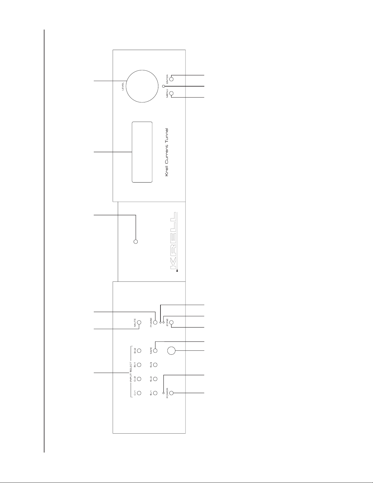
Figure 1 The KCT Front Panel
Power
1 Power Button
2 Stand-by LED
3 Power LED
Remote Control Functions
4 Infrared Sensor
5 Infrared Transmitter LED
1
Preamplifier Functions
6 Input Select Buttons
7 Tape Button
8 Mute Button
9 Phase Button
10 Zone Button
11 Main Zone LED
12 Zone 2 LED
Display
13 Front Panel Display
Level Control
14 Level Control Knob
Menu Functions
15 Menu Button
16 Enter Button
69 13 14
1
4 527
3
10
11
12
16
15
8
KCT
CLASS A

Front Panel Description
See Figure 1 on page 8
The KCT preamplifier front panel provides power on, input and zone selection, level
control, menu functions, and status display. Front panel features and their descriptions
follow.
Power
1 Power Button
Use this button to switch the KCT between the stand-by and the operational modes.
2 Stand-by LED
The red stand-by LED illuminates when the KCT is plugged into a standard AC wall
receptacle, indicating that the KCT is ready to be switched to the operational mode.
3 Power LED
The blue power LED illuminates when the KCT is in the operational mode and flashes
when remote control signals are received.
Remote Control Functions
4 Infrared Sensor
The infrared sensor receives commands from the KCT remote control. For proper
remote control operation, make sure the infrared sensor is not covered or obstructed.
5 Infrared Transmitter LED
The infrared transmitter LED flashes when the KCT sends infrared signals to another
remote control. See Program Remote Menu, on page 31.
Preamplifier Functions
6 Input Select Buttons
Use these buttons to select the corresponding rear panel input that is connected to a
CAST (C-1, C-2), balanced (B-1, B-2), or single-ended (S-1, S-2, S-3) analog source.
The front panel display (13) shows the active zone, the selected input, and volume
level.
7 Tape Button
Use this button to select the corresponding rear panel input that is connected to a
analog tape source. When
that is the pathway for the tape output. See Tape Output Menu, on page 30.
TAPE is activated, the front panel display (13) shows the zone
8 Mute Button
Use this button to mute the preamplifier output. To unmute, press the mute button
again. To customize mute button operation, see Mute Menu, on page 29.
Krell Current Tunnel 9

9 Phase Button
Use this key to invert the absolute polarity of the variable output 180 degrees for the
selected input. The front panel display (13) shows
INVERT for the negative phase; the
display remains blank for the positive phase.
10 Zone Button
Use this button to select the main zone (the main listening or viewing area) or zone 2
(another listening area).
11 Main Zone LED
The red main zone LED illuminates when the main zone is activated. Zone status is also
shown in the front panel display (13).
12 Zone 2 LED
The green zone 2 LED illuminates when zone 2 is activated. Zone status is also shown
in the front panel display (13).
Display
13 Front Panel Display
The front panel display provides preamplifier status messages, including input and zone
selection, tape output status, volume and balance level, and menu selections.
Level Control
14 Level Control Knob
Use this knob to increase or decrease system volume level or, with the balance key, to
adjust balance. The level control knob is also used to select menu options to customize
the KCT. See Customizing the KCT Preamplifier, on page 26.
Menu Functions
15 Menu Button
Use the menu button to access menu options for customizing the KCT. The front panel
display shows
Preamplifier, on page 26.
16 Enter Button
Use this key to access submenu selections.
MAIN MENU and submenu name. See Customizing the KCT
10 Krell Current Tunnel

Figure 2 The KCT Back Panel
Inputs
17 B-1 and B-2 Left and Right
Balanced Inputs
18 S-1, S-2, and S-3 Left and
Right Single-ended Inputs
19 Tape Left and Right Inputs
20 C-1 and C-2 Left and Right
CAST Inputs
Tape Output
21 Tape Output
Main (Zone) Outputs
22 Preamp Left and Right Outputs
23 CAST Preamp Outputs
Zone 2 Outputs
24 Balanced Left and Right Outputs
25 Single-ended Left and Right
Outputs
Back Panel Remote
Control
Inputs and Outputs
26 Krell Link In and Out
27 12 VDC In and Out
28 RC-5 In
29 RS-232
Phono Stage Connector
30 Phono Power
Power
31 IEC Power Connector
17 20 21 22 23 26 28 271918
30
29 31
24
25

Back Panel Description
See Figure 2 on page 11
The KCT preamplifier back panel provides all input and output connections, remote
control inputs and outputs, and power connection. Back panel features and their
descriptions follow.
Inputs
17 B-1 and B-2 Left and Right Balanced Inputs
The KCT is equipped with two pairs of balanced analog source inputs with XLR
connectors.
18 S-1, S-2, and S-3 Left and Right Single-ended Inputs
The KCT is equipped with three pairs of single-ended analog source inputs with RCA
connectors.
19 Tape Left and Right Inputs
The KCT is equipped with one pair of single-ended tape source inputs with RCA
connectors.
20 C-1 and C-2 Left and Right CAST Inputs
The KCT is equipped with two pairs of CAST inputs with 4-pin bayonet connectors, for
use with Krell CAST-equipped input devices.
Tape Output
21 Tape Left and Right Outputs
The KCT is equipped with one pair of tape outputs with RCA connectors.
Main (Zone) Outputs
The following outputs are for the main zone.
22 Preamp Left and Right Outputs
The KCT is equipped with two pairs of preamplifier outputs: one pair of balanced
outputs with XLR connectors and one pair of single-ended outputs with RCA
connectors.
23 CAST Preamp Outputs
The KCT is equipped with two pairs of CAST preamplifier outputs with 4-pin bayonet
connectors, for use with Krell CAST-equipped amplifiers.
Zone 2 Outputs
The following outputs are for zone 2.
24 Balanced Left and Right Outputs
The KCT is equipped with one pair of balanced outputs with XLR connectors.
12 Krell Current Tunnel

25 Single-ended Left and Right Outputs
The KCT is equipped with one pair of single-ended outputs with RCA connectors.
Back Panel Remote Connections
26 Krell Link In and Out
The KCT is equipped with a Krell Link communications input and output data port. Krell
Link allows synchronized remote power on and off of other components connected with
Krell Link. See Krell Link Connections and Operation, on page 19.
27 12 VDC In and Out
The KCT is equipped with three outputs that send and one input that receives 12 VDC
power on/off (12 V trigger) signals to and from other Krell components and other
devices that incorporate a 12 V trigger. This allows you to turn other components on or
off, or to and from stand-by, through the remote control. When the KCT is switched to
the operational mode and is connected to other components through the 12 V trigger, it
sends a signal that will switch other components, allowing whole systems or parts of
systems to be easily coordinated.
Notes
The 12 VDC output power is limited to 30 ma.
Consult the owner’s reference manual of the components used in a custom installation
to take full advantage of the remote capabilities of the KCT.
28 RC-5 In
The KCT is equipped with an RC-5 input that makes custom installation easy and
secure by accepting baseband RC-5 input commands from hardwired remote
controllers.
29 RS-232
The KCT is equipped with an RS-232 port that receives messages from a computerbased control system, providing integrated control of all preamplifier functions. See the
KCT developer’s reference, “RS-232 Port: Sending Commands and Interpreting Data,”
for more information.
Phono Stage Connector
30 Phono Power
The KCT is equipped with a phono power port, for connecting the KCT with a Krell KPE
phono stage.
Power
31 IEC Power Connector
The IEC power connector is for use with the provided IEC standard 15 amp AC power
cord.
Krell Current Tunnel 13

Figure 3 The KCT Remote Control
32
35
43
45
48
36
34
38
39
40
42
47
49
33
37
41
46
44
Preamplifier Functions
35 Mute Key
36 Phase Key
37 Main Zone Key
38 Z2 Key
39 Input Select Keys
40 Tape Key
Menu Functions
41 Menu Key
42 Enter Key
Level Control
43 Bal(ance) Key
44 Level Keys
Compact Disc Functions
45 Pause Key
46 Stop Key
47 Play Key
48 Track Forward
and Back Keys
49 Search Forward
and Back Keys
Power
32 Power Key
Amplifier Functions
33 Amp Pwr Key
34 Amp Sel(ect) Key
14 Krell Current Tunnel

Remote Control Description
See Figure 3 on page 14
BATTERY INSTALLATION AND REMOVAL
The KCT remote control uses two AAA-size 1.5 Volt batteries. Batteries are included
with the shipment. To install the batteries:
1. Remove the remote control backplate, using the supplied T-10 Torx wrench.
2. Install the batteries, following the battery position diagram on the plastic battery
receptacle.
3. Replace and secure the backplate.
Replace batteries when remote control function becomes intermittent.
Remove batteries if the remote control is not used for a long period of time. Battery
leakage can damage the remote control.
The remote control provides power on, input and zone selections, level and balance
control, menu, and compact disc functions. Remote control keys and their descriptions
follow.
Power
32 Power Key
Use this key to switch the KCT between the stand-by and the operational modes.
Amplifier Functions
33 Amp Pwr Key
Use this key to activate Krell amplifiers connected to your system. The amp pwr key
also activates the control component for amplifiers connected by Krell Link.
34 Amp Sel(ect) Key
Use this key to switch between CAST and balanced inputs on a Krell Full Power
Balanced amplifier connected to your system. The red center LED illuminates when the
CAST output is active.
Preamplifier Functions
35 Mute Key
Use this key to mute the preamplifier output. To unmute, press the mute key again. To
customize mute key operation, see Mute Menu, on page 29.
36 Phase Key
Use this key to invert the absolute polarity of the variable output 180 degrees for the
selected input. The front panel display (13) shows INVERT for the negative phase; the
display remains blank for the positive phase.
Krell Current Tunnel 15

37 Main Zone Key
Use this key to select the main zone (the main listening or viewing area). The red main
zone LED (11) on the front panel illuminates when the main zone is activated.
38 Z2 Key
Use this key to select zone 2. The green zone 2 LED (12) illuminates when zone 2 is
activated.
Note
Both zones can play simultaneously.
39 Input Select Keys
Use these keys to select the corresponding rear panel input that is connected to a
CAST (C-1, C-2), balanced (B-1, B-2), or single-ended (S-1, S-2, S-3) analog source.
The front panel display (13) shows the selected input, the active zone, and volume
level.
40 Tape Key
Use this key to select the corresponding rear panel input that is connected to a tape
analog source. When TAPE is activated, the front panel display (13) shows the zone that
is the pathway for the tape output. See Tape Output Menu, on page 30.
Menu Functions
41 Menu Key
Use this key to access the menu options for customizing the KCT. The front panel
display (13) shows
MAIN MENU and submenu name. See Customizing the KCT
Preamplifier, on page 26.
42 Enter Key
Use this key to access submenu selections.
Level Control
43 Bal(ance) Key
Use this key, along with level keys (44) or level knob (14) on the front panel, to balance
output levels. The front panel display (13) shows balance status for three seconds.
44 Level Keys
Use these keys to increase or decrease system volume level or, with the balance key
(43), to adjust balance. The level keys are also used to select menu options to
customize the KCT. See Customizing the KCT Preamplifier, on page 26.
16 Krell Current Tunnel

Compact Disc Functions
The compact disc keys on the KCT remote control are functional with all Krell compact
disc players.
45 Pause Key
Use this key to temporarily suspend playing the current compact disc track. To resume
playing the track at the point pause was engaged, press pause again or press the play
key (47).
46 Stop Key
Use this key to end compact disc playback.
47 Play Key
Use this key to begin compact disc playback.
48 Track Forward and Back Keys
Use these keys to select and begin playing the track that follows or precedes the current
track.
49 Search Forward and Back Keys
Press and hold these keys to scroll forward or backward through the current track.
Note
For information on track programming functions, refer to the owner’s reference manual
for your Krell compact disc player.
Krell Current Tunnel 17

Connecting the KCT Preamplifier to Your System
See Figure 2 on page 11
INPUT AND OUTPUT CONNECTIONS
Krell recommends using its proprietary Krell CAST system for unparalleled sonic
performance between the KCT and other CAST-equipped components.
The KCT also offers conventional balanced operation. The circuitry and connections
associated with balanced operation not only can minimize sonic loss but also are
immune to induced noise, especially for installations using long cables.
The XLR pin configuration is described below:
Pin 1 Ground
Pin 2 Non-inverting (0°)
Pin 3 Inverting (180°)
Inputs and outputs are located on the KCT back panel. Maintain the correct left/right
orientation.
IMPORTANT
Connecting non-CAST components to CAST inputs or outputs can damage your
equipment and void your warranty. Do not attempt to alter CAST cable ends or CAST
inputs or outputs. It is electrically impossible to convert CAST input/output chassis
mount connectors for balanced or single-ended operation.
Follow these steps to connect the KCT preamplifier to your system.
1. Neatly arrange and organize the wiring to and from the KCT and all components.
Separate AC wires from audio cables to prevent hum or other unwanted noise from
being introduced into the system.
2. Connect the outputs of your source equipment to the appropriate CAST (20),
balanced (17), single-ended (18) or tape (19) inputs on the KCT back panel.
3. Connect the appropriate main (22 or 23) and zone 2 (24 or 25) outputs on the KCT
back panel to your amplifier(s).
4. Connect the KCT to AC power. Connect the AC power cord to the IEC power
connector (31), then plug the AC power cord into the wall.
KRELL KCT appears in the
front panel display (13), indicating that the preamplifier is initializing. After initializing
is complete, the KCT is in the stand-by mode. The red stand-by LED (2) illuminates.
18 Krell Current Tunnel

Krell Link Connections and Operation
Krell Link in/out connectors on the KCT back panel allow you to synchronize remote
control operation for systems that include multiple amplifiers and associated
components. When the Krell Link in/out connectors are used, the remote capabilities of
the linked components are controlled from one amplifier or preamplifier, called the
control component. The linked components respond to stand-by and operational mode
commands from the control component via MIDI cables. See Krell Link, on page 32, for
menu options to customize Krell Link operation.
Note
Krell Link uses standard five pin MIDI communication cables, sometimes called MIDI
Plus cables. MIDI cables can be purchased from your authorized distributor or dealer, or
from an audio supply store.
Connecting Components through Krell Link
1. Turn all components off. This ensures all components are synchronized when the
MIDI cable is connected.
2. Select the component to be the control component. The control component must be
in plain view for proper remote control operation.
3. Connect one end of the MIDI cable to the Krell Link out connector (26) on the control
component back panel.
4. Connect the other end of a MIDI cable to the Krell Link in connector (26) on the back
panel of the next component.
5. To link another component, connect another MIDI cable to the Krell Link out
connector on the back panel of the second component. Connect the remaining end of
the MIDI cable to the Krell Link in connector, on the back panel of a third component.
6. Link additional components, if desired.
The components are now ready for operation with Krell Link.
Krell Link Operation
1. When all components are connected, as described above, place each component in
the stand-by mode. This ensures all components are synchronized when signals from
the control component are sent to linked components.
2. Switch the control component to the operational mode from the component’s front
panel power button or through the power key on the remote control. The linked
components simultaneously switch to the operational mode.
An individual linked component can be switched between the stand-by and the
operational modes from its front panel. Switching a linked component temporarily
breaks the chain of linked components. To re-establish linked operation, return all
components to the stand-by mode.
Krell Current Tunnel 19

Tape Input and Output
The KCT preamplifier has a discrete tape input and output. The tape output is used to
channel a signal from a C-1, C-2, B-1, B-2, S-1, S-2, or S-3 input to a recording device
or processor. You can use the tape feature in two ways:
1. Use the tape input to compare the output signal of a three-head analog tape recorder
to the output signal of an audio source, when making a recording. To activate this
function, select an audio source for recording using either the C-1, C-2, B-1, B-2, S-1,
S-2, or S-3 input select buttons (6) or keys (39). Press the tape button (7) or tape key
(40) to switch between the tape recorder output and the input source.
2. Use the tape output to create a processor loop, when the KCT is connected to a
graphic equalizer or other ancillary equipment. To activate this function, connect the
equipment to the KCT tape outputs (21) as described in the equipment manufacturer’s manual. Press the tape button (7) or tape key (40) to switch between the
processor output and the input source.
For both tape features, the KCT front panel display (13) shows TAPEOUT ZONE 1 or
TAPEOUT ZONE 2, indicating the zone that is the pathway for the tape output. The display
changes to TAPE MONITOR after three seconds.
You can also configure the tape output to record music from an input device through
zone 2 while you listen to music from another input device through the main zone. You
can also record through the main zone and listen through zone 2. To select a zone for
tape output, see Tape Output Menu, on page 30.
20 Krell Current Tunnel

Operating the KCT Preamplifier
The KCT preamplifier is easy to install and operate. Instructions follow for on/off and
stand-by operation, and zone operating options.
IMPORTANT
Always mute or fully attenuate the preamplifier level when switching between active
sources (such as a CD player, tape monitor, or VCR).
Do not change the input connections to the preamplifier while the preamplifier is on.
Use care when setting high playback levels. Always lower the volume level at the first
sign of loudspeaker distress.
ON/OFF AND STAND-BY OPERATION
1. With the KCT plugged into the AC power source and in the stand-by mode (red
stand-by LED [2] illuminated), switch to the operational mode by pressing the front
panel power button (1) or power key (32) on the remote control. The blue power LED
(3) illuminates and there is an audible click. The KCT is ready for operation.
2. With the preamplifier output muted or the volume fully attenuated, select a source
manually through the front panel input select buttons (6) or through the input select
keys (39) on the remote control. Start playing the source. Use the level control knob
(14) or level keys (44) to set the volume to a comfortable listening level.
Note
The KCT automatically plays through the main zone until you select zone 2 operation.
3. To return the KCT to the stand-by mode, press the power button (1) or power key
(32).
Krell recommends leaving the KCT in the stand-by mode when it is not playing music.
If you wish to turn your system off:
Turn your system off if it will not be used for a long period of time.
1. Place the amplifiers in the stand-by mode.
2. Press the power button (1) or power key (32) to switch the KCT to the stand-by
mode.
3. Turn off the amplifiers using the power switch, or unplug the AC power cord.
4. Disconnect the KCT from AC power by unplugging the AC power cord from the wall.
Krell Current Tunnel 21

MAIN ZONE AND ZONE 2 OPERATION
The KCT preamplifier’s two-zone operation offers a number of listening options.
Play Both Zones
This option allows you to play one input device through both zones or play a different
device through each zone simultaneously, and adjust volume levels for each zone.
1. Press the power button (1) or power key (32) to switch the KCT from the stand-by to
the operational mode. The front panel display (13) shows the main zone is active, the
currently selected input, and main zone volume level.
2. Press the input select button (6) or key (39) to select the device you wish to play in
the main zone.
3. Begin playing the device. Use the level control knob (14) or level keys (44) to adjust
main zone volume to the desired level.
4. Press the zone button (10) or Z2 key (38) to select zone 2. The front panel display
shows zone 2 is active, the currently selected input, and zone 2 volume level.
5. Press the input select button (6) or key (39) to choose another device to play in zone
2. You can choose the same input device to play in both zones, if you wish.
6. Begin playing the device. Use the level control knob (14) or level keys (44) to adjust
zone 2 volume to the desired level.
To turn off this option:
1. Press the Z2 key (38) to select zone 2.
2. Press the power button (1) or power key (32) once. This turns off zone 2 and
switches you to the main zone.
3. Press the power button or key again to turn off the main zone and return to the stand-
by mode.
Play Either Zone
This option allows you to play an input device in either the main zone or zone 2.
Main Zone Only
1. Press the power button (1) or power key (32) to switch the KCT from the stand-by to
the operational mode. The front panel display shows the main zone is active, the
currently selected input, and the main zone volume level.
2. Press the input select button (6) or key (39) to select the device you wish to play in
the main zone.
3. Begin playing the device. Use the level control knob (14) or level keys (44) to adjust
the main zone volume to the desired level.
4. Press the main zone key (37) again. The preamplifier returns to the stand-by mode.
22 Krell Current Tunnel

Zone 2 Only
1. With the KCT in the stand-by mode, press the zone button (10) or Z2 key (38). The
front panel display (13) shows zone 2 is active.
2. Press the input select key (39) to select the device you wish to play in zone 2. The
KCT will switch to the operational mode and the device will play in zone 2 only.
3. Press the zone button (10) or Z2 key (38) again. Zone 2 stops playing and the KCT
switches back to the stand-by mode.
Note:
When you press the power button (1) or key (32) to return to the operational mode, the
KCT is in the main zone.
Play and Record
This option allows you to play an input device through the main zone while sending
output from another device through zone 2 for recording. You can also record through
the main zone and listen through zone 2.
1. Press the power button (1) or key (32) to switch the KCT from the stand-by to the
operational mode. The front panel display shows the main zone is active, the
currently selected input, and main zone volume level.
2. Press the input select button (6) or key (39) to select the input device that you want to
play through the main zone.
3. Begin playing the device. Use the level control knob (14) or level keys (44) to adjust
the main zone volume to the desired listening level.
4. Press the menu button (15) or key (41) to select the main menu. The front panel
display (13) shows
5. Use the level control knob (14) or level keys (44) to select the
MENU.
TAPE OUTPUT MENU.
6. Press the enter button (16) or key (42) to access the submenu. The front panel
display shows
7. Use the level control knob (14) or level keys (44) to select
OUTPUT FROM ZONE1.
OUTPUT FROM ZONE2.
8. Press the menu button or key to exit the main menu.
9. Press the zone button (10) or Z2 key (38) to select zone 2.
10. Press the input select button (6) or key (39) to select the input device that you want
to record through zone 2. Begin playing the device.
11. Press the tape button (7) or key (40). The front panel display shows TAPEOUT ZONE2.
The input will begin recording through zone 2. The front panel display shows TAPE
MONITOR
after three seconds.
While you are recording through zone 2, you can also press the zone button (10) or
main zone key (37) to check playback through the main zone, without interrupting the
recording through zone 2.
Krell Current Tunnel 23

To stop recording:
1. Press the zone button (10) or Z2 key (38) to select zone 2.
2. Press the tape button (7) or key (40).
24 Krell Current Tunnel

Troubleshooting System Noise
When you mix and match high-performance audio components, each with its own
ground potential, a low frequency hum may occur in one or both loudspeakers. If this
happens when you place the KCT preamplifier into your system, follow these simple
troubleshooting steps.
1. Check that all input and output connections are of sound construction.
2. With the preamplifier off, remove the interconnect cables, then turn the preamplifier
on. If the hum disappears, turn the preamplifier off and reinsert one of the
interconnect cables. Turn the amplifier back on. Repeat this process for each cable.
3. If the hum reappears with one or both interconnect cables reinserted, the cable needs
to be replaced.
4. If the interconnect cables are sound, you may be experiencing a ground loop. Please
contact your authorized Krell dealer, distributor, or Krell for suggestions on how to
eliminate it.
Krell Current Tunnel 25

Customizing the KCT Preamplifier
The KCT preamplifier’s easy-to-use menu options allow you to select and set preferred
operating options for balance, inputs, trims, Theater Throughput mode, display
brightness, mute, trigger setup and delay, tape output, AC mains, remote programming,
setup memory, and Krell Link. The instructions below follow the menu order on your
KCT.
IMPORTANT
You do not need to press enter to set a selection. The last selection chosen is the one
entered in the system.
If at any time you wish to exit the menu without changing the settings, select EXIT MENU
(the last menu option) and press the enter button or key.
Z1 AND Z2 BALANCE
This option allows you to add a fixed positive offset to the main zone and zone 2
balance. With this feature, you can set the balance that is unique to your system’s
configuration.
1. Press the menu button (15) or key (41) to access the main menu.
2. The front panel display (13) reads Z1 BALANCE (the default).
3. Press the enter button (16) or key (42). The front panel display shows ZONE 1
BALANCE and the current balance setting.
4. Use the level control knob (14) or level keys (44) to adjust the balance to the desired
setting from 0 to +6 dB, in .5 dB increments.
5. Press the enter button (16) or key (42) to return to the main menu or press the menu
button (15) or key (41) to exit the menu mode.
To adjust the fixed offset for zone 2:
1. Press the menu button (15) or key (41) to select the main menu
2. Use the level control knob (14) or level keys (44) to select Z2 BALANCE.
3. Repeat steps 4 and 5 above.
INPUT NAME MENU
This option allows you to assign names to all inputs, for easy identification.
1. Press the menu button (15) or key (41) to access the main menu.
2. Use the level control knob (14) or level keys (44) to select INPUT NAME MENU.
3. Press the enter button (16) or key (42). The front panel display (13) shows INPUT
NAMES
26 Krell Current Tunnel
and S-1 (the default).

4. Use the level control knob (14) or level keys (44) to select the desired input from the
list (S-1, B-1, C-1, tape, etc.).
5. Press the enter button (16) or key (42) to access the submenu.
6. Use the level control knob (14) or level keys (44) to scroll through the list of naming
options (phono, aux, etc.). The front panel display (13) will show the new input name
when you exit the menu.
7. To name another input, press the enter button (16) or key (42) to return to the input
name menu.
8. Repeat steps 4 through 6.
9. Press the menu button (15) or key (41) to exit the menu mode.
INPUT LEVEL TRIM
This option allows you to add a fixed positive or negative volume offset to compensate
for input devices with significantly different output levels. After adjusting input level trim,
you can switch between these input devices without major changes in volume.
1. Press the menu button (15) or key (41) to access the main menu.
2. Use the level control knob (14) or level keys (44) to select
3. Press the enter button (16) or key (42). The front panel display (13) shows
LEVEL TRIMS
and S1 (the default).
INPUT LEVEL TRIM.
INPUT
4. Use the level control knob (14) or level keys (44) to select the desired input from the
list (S-1, B-1, tape, etc).
5. Press the enter button (16) or key (42). The front panel display (13) shows the
existing volume.
6. Use the level control knob (14) or level keys (44) to scroll through the available
volume settings from –6 to +6 dB, in .5 dB increments.
7. To adjust level trim for another input, press the enter button (16) or key (42) to return
to the input level trim menu.
8. Repeat steps 4 through 6.
9. Press the enter button (16) or key (42) to return to the main menu, or press the menu
button (15) or key (41) to exit the menu mode.
INPUT BALANCE TRIM
This option allows you to add different left and right balance offsets for different inputs.
1. Press the menu button (15) or key (41) to access the main menu.
2. Use the level control knob (14) or level keys (44) to select
Krell Current Tunnel 27
INPUT BALANCE TRIM.

3. Press the enter button (16) or key (42). The front panel display (13) shows INPUT
BALANCE TRIM
and S-1 (the default).
4. Use the level control knob (14) or level keys (44) to select the desired input
(S-1, B-1, tape, etc.).
5. Press the enter button (16) or key (42). The front panel display (13) shows the current
balance of the selected input.
6. Use the level control knob (14) or level keys (44) to scroll through the list of available
balance offsets from 0 to +6 dB, right and left, in .5 dB increments.
7. To set the balance trim for another input, press the enter button (16) or key (42) to
return to the input balance trim menu.
8. Repeat steps 4 through 6.
9. Press the enter button (16) or key (42) to return to the main menu, or press the menu
button (15) or key (41) to exit the menu mode.
THEATER (THROUGHPUT) MODE
This option allows you to simplify the integration of an audio/video surround sound
processor into your system by setting the CAST, balanced, or single-ended inputs to
operate as a unity gain stage. Krell calls this configuration Theater Throughput.
When you configure a KCT input for Theater Throughput, the KCT volume and balance
controls are transferred to the audio/video surround sound processor, for integrated
volume and balance management and ease of operation. As long as the KCT input is
configured for Theater Throughput and connected to the audio/video surround sound
processor’s main outputs, all system volume and balance adjustments are made
through the surround sound processor. When you disengage the KCT input from
Theater Throughput, the volume and balance controls revert to the KCT.
1. Press the menu button (15) or key (41) to access the main menu.
2. Use the level control knob (14) or level keys (44) to select
THEATER MODE.
3. Press the enter button (16) or key (42). The front panel display (13) shows THEATER
and S-1.
MODE
4. Use the level control knob (14) or level keys (44) to select the input to be placed in
Theater Throughput mode.
5. Press the enter button (16) or key (42). The front panel display (13) shows OFF (the
default).
6. Use the level control knob (14) or level keys (44) to select whether Theater
Throughput mode is off or on.
7. To select or disengage Theater Throughput for another input, press the enter button
(16) or key (42) to return to the theater mode menu.
28 Krell Current Tunnel

8. Repeat steps 4 through 6.
9. Press the menu button (15) or key (41) to exit the menu mode.
BRIGHTNESS
This option allows you to adjust the front panel display brightness.
1. Press the menu button (15) or key (41) to access the main menu.
2. Use the level control knob (14) or level keys (44) to select
BRIGHTNESS.
3. Press the enter button (16) or key (42). The front panel display (13) shows HIGH (the
default).
4. Use the level control knob (14) or level keys (44) to select the desired brightness
option (HIGH, FULL, BRIGHTNESS OFF, LOW, AND MEDIUM). The front panel display (13)
illustrates each level of brightness.
5. Press the enter button (16) or key (42) to return to the main menu or press the menu
button (15) or key (41) to exit the menu mode.
Note
If you choose OFF, the front panel display will remain on until you exit the menu mode.
Press menu again to display the main menu.
MUTE MENU
This option allows you to customize mute button or mute key to operate in either the
main zone or zone 2, only in the zone that is currently active, or in both zones.
1. Press the menu button (15) or key (41).
2. Use the level control knob (14) or level keys (44) to select MUTE MENU.
3. Press the enter button (16) or key (42). The front panel display (13) shows MUTE
ACTIVE
ZONE (the default).
4. Use the level control knob (14) or level keys (44) to highlight the mute options (MUTE
1, MUTE ZONE 2, MUTE BOTH ZONES, MUTE ACTIVE ZONE).
ZONE
5. Press the enter button (16) or key (42) to return to the main menu or press the menu
button (15) or key (41) to exit the menu mode.
OUTPUT TRIGGER SETUP
This option allows you to configure the activation of three 12 VDC (12 Volt trigger)
outputs to be always off or on, or to activate only with selected zones.
1. Press the menu button (15) or key (41) to access the main menu.
2. Use the level control knob (14) or level keys (44) to select OUTPUT TRIGGER SETUP.
3. Press the enter button (16) or key (42). The front panel display (13) shows TRIGGER 1.
Krell Current Tunnel 29

4. Use the level control knob (14) or level keys (44) to select the desired trigger
(1, 2, or 3).
5. Press the enter button (16) or key (42) again. The front panel display (13) shows
ALWAYS OFF (the default).
6. Use the level control knob (14) or level keys (44) to select the desired trigger option
ALWAYS OFF, ON FOR ZONE 1, ON FOR ZONE 2, ON FOR BOTH ZONES, ALWAYS ON).
(
7. To configure another trigger, press the enter button (16) or key (42) to return to the
output trigger setup menu.
8. Repeat steps 4 through 6.
9. Press the menu button (15) or key (41) to exit the menu mode.
TAPE OUTPUT MENU
This option allows you to choose the zone through which the tape output receives its
signal. With this option you can record music from one input device through one zone
while listening to music from another device through the other zone.
1. Press the menu button (15) or key (41) to access the main menu.
2. Use the level control knob (14) or level keys (44) to select
TAPE OUTPUT.
3. Press the enter button (16) or key (42). The front panel display (13) shows
OUTPUT FROM ZONE1 (the default).
4. Use the level control knob (14) or level keys (44) to select the desired output (OUTPUT
FROM ZONE
1, OUTPUT FROM ZONE2).
5. Press the enter button (16) or key (42) to return to the main menu or press the menu
button (15) or key (41) to exit the menu mode.
AC MAINS MENU
This option allows the KCT to go directly from off to the operational mode and bypass
the stand-by mode.
1. Press the menu button (15) or key (41) to access the main menu.
2. Use the level control knob (14) or level keys (44) to select ACMAINS MENU.
3. Press the enter button (16) or key (42). The front panel display (13) shows ACMAINS
OFF
(the default).
4. Use the level control knob (14) or level keys (44) to select ACMAINS OFF or ACMAINS ON.
5. Press the enter button (16) or key (42) to return to the main menu or press the menu
button (15) or key (41) to exit the menu mode.
30 Krell Current Tunnel

PROGRAM REMOTE MENU
This option allows the KCT to send its remote control commands to a learning or
programmable remote control.
Note
You must place the programmable remote in front of the KCT infrared sensor to send
remote control commands.
1. Press the menu button (15) or key (41) to access the main menu.
2. Use the level control knob (14) or level keys (44) to select
PROGRAM REMOTE MENU.
3. Press the enter button (16) or key (42). The front panel display (13) shows S1 SELECT
(the default).
4. Use the level control knob (14) or level keys (44) to scroll through all the remote
control command options.
5. Press the enter button (16) or key (42). The front panel display (13) shows
TRANSMITTING.
6. To select additional commands, press the enter button (16) or key (42) to return to
the program remote menu.
7. Repeat steps 4 and 5 to select and transmit additional commands.
8. The last command on the submenu is
EXIT. Select EXIT and press the enter button
(16) or key (42) to return to the main menu.
9. Press the menu button (15) or key (41) to exit the menu mode.
INPUT TRIGGER SETUP
This option allows you to configure which zone is activated by the 12 VDC (12 Volt
trigger) input.
1. Press the menu button (15) or key (41) to access the main menu.
2. Use the level control knob (14) or level keys (44) to select
INPUT TRIGGER SETUP.
3. Press the enter button (16) or key (42). The front panel display (13) shows TURN ON
BOTH
(the default).
4. Use the level control knob (14) or level keys (44) to select the preferred input trigger
setup option (TURN ON BOTH, INACTIVE, TURN ON ZONE 1, TURN ON ZONE 2).
5. Press the enter button (16) or key (42) to return to the main menu or press the menu
button (15) or key (41) to exit the menu mode.
Krell Current Tunnel 31

SETUP MEMORY
This option allows you to save or recall new settings, or reset all settings to the factory
defaults. Remember, to exit the setup memory without altering the settings, select exit
and press the enter button (16) or key (42). You return to the main menu.
1. Press the menu button (15) or key (41) to access the main menu.
2. Use the level control knob (14) or level keys (44) to select
SETUP MEMORY.
3. Press the enter button (16) or key (42). The front panel display (13) shows SAVE ALL
SETTINGS
(the default).
4. Use the level control knob (14) or level keys (44) to select the preferred setup
memory (SAVE ALL SETTINGS, RECALL ALL SETTINGS, FACTORY SETTINGS).
5. Press the enter button (16) or key (42). The front panel display (13) shows PLEASE
WAIT
. The KCT switches into the stand-by mode and reinitializes. The front panel
display shows
KRELL KCT.
6. Press the power button (1) or key (32) to return the KCT to the operational mode. The
settings you selected are stored.
KRELL LINK
This option allows you to customize the operation of the KCT and Krell amplifiers
connected with Krell Link. See Krell Link Connections and Operation, on page 19.
1. Press the menu button (15) or key (41) to access the main menu.
2. Use the level control knob (14) or level keys (44) to select KRELL LINK.
3. Press the enter button (16) or key (42). The front panel display (13) shows DISABLED
(the default).
4. Use the level control knob (14) or level keys (44) to select the preferred Krell Link
option (DISABLED, ENABLED, AUTO ON).
Following are the definition of terms used with Krell Link.
Disabled. The amplifiers connected through Krell Link remain off when the KCT is
switched to the operational mode, for example, if you wish to record without listening to
music. The amplifiers can not be powered on when this option is engaged.
Enabled. The amplifiers connected through Krell Link remain off when the KCT is
switched to the operational mode. To turn the amplifiers on and off, use the amp pwr
key (33) on the KCT remote control.
Auto On. The amplifiers connected through Krell Link automatically power on when you
switch the KCT to the operational mode and power off when you turn the KCT off.
5. Press the enter button (16) or key (42) to return to the main menu or press the menu
button (15) or key (41) to exit the menu mode.
32 Krell Current Tunnel

TRIGGER DELAY SETUP
This option allows you to customize the number of seconds (from 0 to 5) before a trigger
activates.
1. Press the menu button (15) or key (41) to access the main menu.
2. Use the level control knob (14) or level keys (44) to select
TRIGGER DELAY SETUP.
3. Press the enter button (16) or key (42). The front panel display (13) shows TRIGGER 1.
4. Use the level control knob (14) or level keys (44) to select the trigger (1, 2, or 3) that
you wish to configure.
5. Press the enter button (16) or key (42).
6. Use the level control knob (14) or level keys (44) to select the trigger delay time (from
0 to 5 seconds).
7. To configure the delay for another trigger, press the enter button (16) or key (42) to
return to the trigger delay setup menu.
8. Repeat steps 4 through 6.
9. Press the enter button (16) or key (42) to return to the main menu or press the menu
button (15) or key (41) to exit the menu mode.
EXIT MENU
This option allows you to exit the menu mode after you have set all preferred
configuration options. Exit also allows you to exit any menu or submenu without
changing the settings.
1. Press the menu button (15) or key (41) to access the main menu.
2. Use the level control knob (14) or level keys (44) to select EXIT MENU.
3. Press the enter button (16) or key (42). You exit the menu mode.
Krell Current Tunnel 33

Questions and Answers
Q. Should I leave my KCT on at all times?
A. Yes, Krell recommends that you leave your KCT preamplifier in the stand-by mode
when it is not playing music. Turn your system off only if it will not be used for a long
period of time.
Q. When I turn on the KCT there is a loud hum through the loudspeakers. What should
I do?
A. When a new component is introduced into your system, a low frequency hum may
occur in one or both loudspeakers. Check all input and output connections and cables,
making sure they are of sound construction (see Troubleshooting System Noise, on
page 25). If the interconnects and cables are sound, you may be experiencing a ground
loop, which can often be easily eliminated. Please contact your authorized dealer,
distributor, or Krell for suggestions.
Q. Can I use the KCT CAST inputs or outputs with other manufacturers’ components?
A. No. Only CAST-equipped components can be connected to CAST inputs or outputs.
Connecting non-CAST components to these inputs or outputs can damage your
equipment and void your warranty. See Connecting the KCT Preamplifier to your
System, on page 18.
Q. I want my CD player to play through the main zone and the radio to play through
zone 2. Can I play one louder than the other?
A. Yes. Each zone on the KCT has independent volume control, so you can play music
from one input device at the desired volume through the main zone, and play a second
device through zone 2 at a different volume. You can also play an input device through
one zone and record through the other zone, again, at separate volume levels. See
Main Zone and Zone 2 Operation, on page 22. Remember that you’ll need one
amplifier to drive your loudspeakers in the main zone and a second amplifier for the
loudspeakers in zone 2.
Q. When I select the B-1 input on the KCT, one channel seems to have less gain than
the other does. Is something wrong?
A. First, check the balance level using the balance and level keys. (See Remote
Control Description, on page 15.). If balance level is correct, check that the balanced
input or output internal cable terminations are properly connected. Locate the channel
that appears to have less gain. Switch that channel's input cables. If the problem now
appears in the other channel, the cable is defective. If the problem remains in the
original channel, check the output cables using the same procedure.
If the balance settings or cables are not causing the difference in gain, contact your
authorized Krell
34 Krell Current Tunnel
dealer, distributor, or Krell.

Krell Current Tunnel 35
This Krell product has a limited warranty of five years for parts and labor on circuitry. Should
this product fail to perform at any time during the warranty, Krell will repair it at no cost to the
owner, except as set forth in this warranty.
The warranty does not apply to damage caused by acts of God or nature.
The warranty on this page shall be in lieu of any other warranty, expressed or implied, includ-
ing, but not limited to, any implied warranty of merchantability or fitness for a particular purpose.
There are no warranties which exceed beyond those described in this document. If this product
does not perform as warranted herein, the owner’s sole remedy shall be repair. In no event will
Krell be liable for incidental or consequential damages arising from purchase, use, or inability to
use this product, even if Krell has been advised of the possibility of such damages.
Proof of purchase in the form of a bill of sale or receipted invoice substantiating that the unit is
within the warranty period must be presented to obtain warranty service. The warranty begins
on the date of the original retail purchase, as noted on the bill of sale or receipted invoice from
an authorized Krell dealer or distributor. Previously owned equipment, when repurchased
from an authorized Krell dealer or distributor, has the balance of the original warranty, based on
the original date of manufacture.
The warranty for Krell products is valid only in the country to which they were originally shipped,
through the authorized Krell distributor for that country, and at the factory. There may be restrictions on or changes to Krell’s warranty because of regulations within a specific country. Please
check with your distributor for a complete understanding of the warranty in your country.
If a unit is serviced by a distributor who did not import the unit, there may be a charge for service, even if the product is within the warranty period.
Freight to the factory is your responsibility. Return freight within the United States (U.S.A.) is
included in the warranty. If you have purchased your Krell product outside the U.S.A. and wish
to have it serviced at the factory, all freight and associated charges to the factory are your
responsibility.
Krell will pay return freight to the U.S.A.-based freight forwarder of your choice. Freight and
other charges to ship the unit from the freight forwarder to you are also your responsibility.
Krell is not responsible for any damage incurred in transit. Krell will file claims for damages as
necessary for units damaged in transit to the factory. You are responsible for filing claims for
shipping damages during the return shipment.
Krell does not supply replacement parts and/or products to the owner of the unit. Replacement
parts and/or products will be furnished only to the distributor performing service on this unit on
an exchange basis only; any parts and/or products returned to Krell for exchange become the
property of Krell.
No expressed or implied warranty is made for any Krell product damaged by accident, abuse,
misuse, natural or personal disaster, or unauthorized modification.
Any unauthorized voltage conversion, disassembly, component replacement, perforation of chassis, updates, or modifications performed to the unit will void the warranty.
The operating voltage of this unit is determined by the factory and can only be changed by an
authorized Krell distributor or at the factory. The voltage for this product in the U.S.A. cannot be
changed until six months from the original purchase date.
In the event that Krell receives a product for warranty service that has been modified in any
way without Krell authorization, all warranties on that product will be void. The product will be
returned to original factory layout specifications at the owner’s expense before it is repaired. All
repairs required after the product has been returned to original factory specifications will be
charged to the customer, at current parts and labor rates.
All operational features, functions, and specifications and policies are subject to change without
notification.
Warranty
To register your product
for warranty benefits, please
complete and return the
Warranty Registration Card
enclosed in the shipping box
within 15 days of purchase.
Thank you.

36 Krell Current Tunnel
Return Authorization
Procedure
If you believe there is a problem with your component, please contact your dealer, distributor, or the Krell factory to discuss the problem
before you return the component for repair. To expedite service, you
may wish to complete and e-mail the Service Request Form in the
Service section of our website at:
http://www.krellonline.com
To return a product to Krell, please follow this procedure so that we
may serve you better:
1. Obtain a Return Authorization Number (R/A number) and shipping address from the Krell Service Department.
2. Insure and accept all liability for loss or damage to the product
during shipment to the Krell factory and ensure all freight (shipping) charges are prepaid.
The product may also be hand delivered if arrangements with the
Service Department have been made in advance. Proof of purchase
will be required for warranty validation at the time of hand delivery.
Use the original packaging to ensure the safe transit of the product to
the factory, dealer, or distributor. Krell may, at its discretion, return a
product in new packaging and bill the owner for such packaging if the
product received by Krell was boxed in nonstandard packaging or if
the original packaging was so damaged that it was unusable. If Krell
determines that new packaging is required, the owner will be notified
before the product is returned.
HOW TO RETURN
A PRODUCT
IMPORTANT
To purchase additional packaging, please contact your authorized
Krell dealer, distributor, or the Krell Service Department for assistance.
HOW TO PURCHASE
ADDITIONAL PACKING
To contact the Krell Service Department:
TEL 203-799-9954
Monday-Friday, 9:00 am to 5:00 pm EST
FAX 203-799-9796
E-MAIL service@krellonline.com
WEB SITE http://www.krellonline.com
Your KCT product serial number is:
SERIAL NUMBER
HOW TO EXPEDITE
SERVICE

Specifications
Inputs 2 pr. CAST (Lemo)
2 pr. Balanced (XLR)
3 pr. Single-ended (RCA)
Main Outputs 2 pr. CAST (Lemo)
1 pr. Balanced (XLR)
1 pr. Single-ended (RCA)
Zone 2 Outputs 1 pr. Balanced (XLR)
1 pr. Single-ended (RCA)
Tape Loop 1 pr. Single-ended Inputs (RCA), 1 pr. Single-ended Record
Outputs (RCA), Buffered, with Programmable Zone
Control Inputs 1 RS-232 Input (9-pin D-subminiature Connector)
1 RC-5 Input (1/4-inch Coaxial Connector)
1 12V Trigger Input (3.5mm Connector)
Control Outputs 3 Individually Programmable 12V Triggers
(3.5mm Connector), 1 Krell Remote Link (5-pin DIN
Connector)
Power Inputs 1 IEC AC Mains Receptacle
Power Outputs 1 ±20V DC for KPE (9-pin D-subminiature Connector)
Voltage Gain 12 dB (Balanced Output),
6 dB (Single-ended Output)
Current Gain 12 dB (CAST Output)
Volume Controls 16-bit Discrete R-2R Ladder (Main Zone)
16-bit Multiplying DAC (Zone 2)
Input Overload 12 mA RMS CAST
12 V RMS Balanced or Single-ended
Output Overload 7 V RMS Single-ended
14 V RMS Balanced
14 mA RMS CAST
Krell Current Tunnel 37

Frequency Response 0.4 Hz-220 kHz ±0.1 dB (Main Zone)
0.1 Hz-1.5 MHz ±3 dB (Main Zone)
0.9 Hz-100 kHz ±0.1 dB (Zone 2)
0.4 Hz-400 kHz ±3 dB (Zone 2)
THD+Noise <0.005% 20 Hz-20 kHz Balanced or Single-ended
<0.004% 20 Hz-20 kHz CAST
Residual Noise <-95 dB, wideband, unweighted
<-109 dB, “A”-weighted
AC Mains Requirements 100, 120, 200, 220, or 240 V AC; 50 or 60 Hz; 60 W
Dimensions 19w x 4.5h x 14.5d in.
48w x 11.5h x 36.5d cm
Weight Shipping 23 lb., 10.5 kg
Unit Only 19 lb., 8.6 kg
38 Krell Current Tunnel


Krell Industries, Inc.
45 Connair Road
Orange, CT 06477-3650 USA
TEL 203-799-9954, FAX 203-891-2028
E-MAIL krell@krellonline.com
WEBSITE http://www.krellonline.com
KCT
Krell Current Tunnel
CAST Preamplifier
v 01.0
 Loading...