

THE LEADER IN AUDIO ENGINEERING
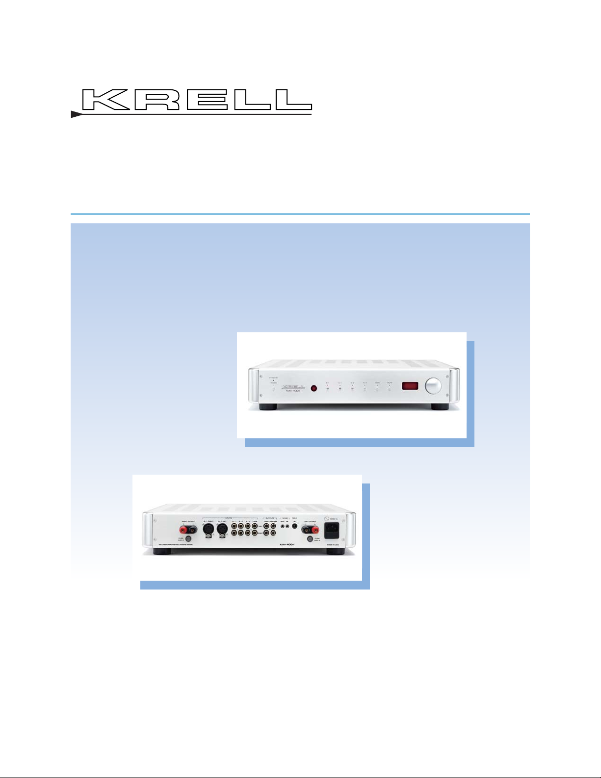
KAV–400xi
Remote Control
Integrated Amplifier
Instructions for Use
Owner’s Reference

This product is manufactured in the United States of America. Krell®is a registered trademark of Krell
Industries, Inc., and is restricted for use by Krell Industries, Inc., its subsidiaries, and authorized agents.
Krell Current Mode™ and Theater Throughput™ are trademarks of Krell Industries, Inc. All other trademarks and tradenames are registered to their respective companies.
© 2003 by Krell Industries, Inc. All rights reserved P/N 306733
Krell Industries, Inc.
45 Connair Road
Orange, CT 06477-3650 USA
TEL 203-799-9954
FAX 203-891-2028
E-MAIL krell@krellonline.com
WEBSITE http://www.krellonline.com
This product complies with the EMC directive (89/336/EEC) and the low-voltage
directive (73/23/EEC).
Do not place the integrated amplifier where it could be exposed to dripping or
splashing.
The ventilation grids on the top and bottom of the KAV–400xi must be unobstructed at all times during operation. Do not place flammable material on top of
or beneath the component.
When making connections to this or any other component, make sure all components are off. Turn off all systems’ power before connecting the KAV–400xi to any
other component. Make sure all cable terminations are of the highest quality, free
from frayed ends, short circuits, or cold solder joints.
THERE ARE NO USER-SERVICEABLE PARTS INSIDE ANY KRELL PRODUCT.
Please contact your authorized dealer, distributor, or Krell if you have any ques-
tions not addressed in this reference manual.
KAV–400xi
Remote Control Integrated Amplifier
Instructions for Use
v 03.0
CONTACT
INFORMATION
WARNINGS

Krell KAV–400xi iii
Contents
Page
INTRODUCTION 1
DEFINITION OF TERMS 2
UNPACKING 4
PLACEMENT 5
AC Power Guidelines 5
Power Cord 5
FRONT PANEL / REMOTE CONTROL DESCRIPTION 7
REMOTE CONTROL ONLY 9
Battery Installation and Removal 9
Remote Control Only Functions 9
BACK PANEL DESCRIPTION 12
CONNECTING THE KAV–400xi TO YOUR SYSTEM 14
Connection Steps 14
OPERATING YOUR KAV–400xi 15
Amplifier Operation 15
Tape Input and Output 16
OPTIONAL CONFIGURATIONS 17
Configuring the KAV–400xi for Theater Throughput 17
Preamplifier Output 18
HOW TO TROUBLESHOOT SYSTEM NOISE 19
QUESTIONS AND ANSWERS 20
WARRANTY 21
RETURN AUTHORIZA TION PROCEDURE 22
SPECIFICATIONS 23

iv Krell KAV–400xi
Illustrations
FIGURE 1 The KAV–400xi Front Panel 6
FIGURE 2 The KAV–400xi Remote Control 6
FIGURE 3 The KAV–400xi Back Panel 11
Page

Krell KAV–400xi 1
Introduction
Thank you for your purchase of the Krell KAV–400xi Remote
Control Integrated Amplifier. This fully integrated amplifier and preamplifier has a fully balanced signal path from input to output and
employs a wide bandwidth design with low negative feedback for
sonic accuracy throughout the frequency spectrum. All circuits up
to the driver stage are pure Class A.
Krell’s new surface mount technology (SMT) means that the
KAV–400xi is an integrated amplifier with big power—200 Watts
per channel—that does not require big space. SMT allows individual circuit elements to be placed very close together. This shortens
signal paths and allows circuit elements to operate at the same
temperature, resulting in more accurate signal transfer and
enhanced reliablilty.
The KAV–400xi is easy to operate and integrate into your system.
The remote control accesses all amplifier functions, and remote
control connection options allow the KAV–400xi to be easily connected with other components. The Theater Throughput feature
provides easy integration of the amplifier into a home theater
system.
This owner’s reference manual contains important information on
the placement, installation, and operation of the KAV–400xi.
Please read this information carefully. Athorough understanding of
these details will help ensure satisfactory operation and long life
for your KAV–400xi and related system components.

Definition of Terms
OPERA TION
Following are the definitions of key terms used in your owner’s reference manual.
Theater Throughput
Theater Throughput is a Krell configuration option that allows the
signal from a surround preamp/processor to pass through a Krell
preamplifier or integrated amplifier with no gain, for integrated volume and balance management of Krell home theater systems.
Balanced
A symmetrical input or output circuit that has equal impedance
from both input terminals to a common ground reference point.
The industry standard for professional and sound recording installations, balanced connections have 6 dB more gain than singleended connections and allow the use of long interconnect cables.
Balanced connections are completely immune to induced noise
from the system or the environment.
Single-ended
A two-wire input or output circuit. Use care when using singleended connections as the ground connection is made last and
broken first. Turn the system off prior to making or breaking singleended connections. Single-ended connections are not recommended for connections requiring long cable runs.
Off
The component is off when the AC power cord is unplugged from
the wall receptacle.
Stand-by Mode
Alow power consumption status that keeps the audio circuits at
idle. When you plug the AC power cord into the wall receptacle,
the red stand-by LED illuminates. The component is now ready to
be switched to the operational mode. Krell recommends leaving
the component in the stand-by mode when it is not playing music.
Operational Mode
When the component is in the stand-by mode, and you press the
power button on the front panel or the power key on the remote
control, the blue power LED illuminates. The component is in the
operational mode and is ready to play music.
CONFIGURATIONS
INPUT AND OUTPUT
CONNECTIONS
2 Krell KAV–400xi

Definition of Terms, continued
Krell Current Mode
A proprietary Krell circuit topology in which the audio gain stages
of a component operate in the current rather than voltage domain.
This unique technology provides the component with exceptional
speed and a wide bandwidth.
TECHNOLOGY
Krell KAV–400xi 3

4 Krell KAV–400xi
Unpacking
Follow these steps to safely unpack the KAV–400xi:
1. Open the shipping box and remove the top layer of foam. The
KAV–400xi and the KAV–400xi accessory kit containing the
following items are visible:
1 AC power cord
1 12 VDC (12 V trigger) cable
2 spare loudspeaker fuses (AGC 8)
1 KAV–400xi remote control
1 CR2025 lithium battery
1 packet containing the Quick Setup Guide
and the warranty registration card
2. Grasp the underside of the amplifier and lift it straight out of
the packing box.
3. Place the amplifier in a safe location and remove the protective
plastic wrapping.
I
f any of these items are not included please contact your authorized
Krell dealer.
Save all packing materials. If you must ship your KAV –400xi in the future,
repack the unit in its original packaging to prevent shipping damage.
Notes

Krell KAV–400xi 5
Placement
Before you install the KAV–400xi into your system, review the following guidelines to choose the location for the KAV–400xi. This
will facilitate a clean, trouble-free installation. The KAV– 400xi does
not require any type of special rack or cabinet for installation. For
the dimensions of the KAV–400xi, see Specifications, on the
back cover.
Place the KAV–400xi on a firm, level surface, away from excessive heat, humidity, or moisture. The KAV– 400xi requires at least
two inches (5 cm) of clearance on each side and at least two inches (5 cm) of clearance above and below the component to provide
adequate ventilation. Installations inside cabinetry may need extra
ventilation.
The KAV–400xi is not hum-sensitive. Other components may be
placed on or around the KAV–400xi (make sure ventilation grids
remain unobstructed).
Place the amplifier as close to the loudspeakers as possible and
keep loudspeaker cable lengths to a minimum. Loudspeaker cable
adds impedance to the load the amplifier must drive, regardless of
the cable’s gauge. All Krell amplifiers drive the lowest impedances
with ease, but long loudspeaker cables reduce the maximum
power that can be delivered to the loudspeakers.
The KAV–400xi has superb regulation and does not require a dedicated AC circuit. Avoid connections through extension cords or
multiple AC adapters. High quality 15 amp grounded AC strips are
acceptable. High quality AC line conditioners or filters may be
used if they are grounded and meet or exceed the unit’s maximum
power consumption of 1800 Watts.
The KAV–400xi should be operated only with the power cord
supplied. Please contact your authorized Krell dealer, distributor,
or Krell before using any devices designed to alter or stabilize the
AC power for the KAV–400xi.
AC Power
Guidelines
Power Cord

Figure 1 The KAV–400xi Front Panel
2 71 4
11
6 91083
5
KAV–400xi
Figure 2 The KAV–400xi Remote Control
Note
Remote control keys listed above function with the KAV–400xi. Other keys
on this remote control may activate other Krell components. Consult the
Krell reference manual for each model to review your component’s full
remote control capabilities.
6 Krell KAV–400xi
Power
1 Power Button
2 Power LED
3Stand-by LED
4 Infrared Sensor
12 Pre Key (Remote)
Analog Devices
5 S-1, S-2, S-3, and
B-1, Buttons, Keys
and LEDs
6Tape Button or Key
7Tape LED
Mode Indicators
8 Mute Button or Key
9 Mute LED
Volume Adjustment
Functions
10 Level Knob / Level Keys
11 Front Panel Display
13 Bal (Balance) Keys
(Remote)
1 12
8
10
13
Activates the
6
KAV—400xi remote
to access amplifier
commands
5

Front Panel/ Remote Control Description
See Figures 1 and 2 on page 6
Krell KAV–400xi 7
Power, analog input selections, and volume control accessed via
the front panel of the KAV–400xi are described in the illustration
legend below. The front panel display shows volume and balance
levels, and Theater Throughput status. Most front panel features
can also be activated via the keys on the remote. Descriptions of
special operational features of the remote control are outlined on
pages 9-10:
1 Power Button or Key
Use this button to switch the KAV–400xi between the stand-by
and the operational modes.
2 Power LED
The blue power LED illuminates when the KAV–400xi is in the
operational mode. The power LED also flashes when any remote
control key is pressed.
3 Stand-by LED
The red stand-by LED illuminates when the KAV–400xi is plugged
into a standard AC wall receptacle, indicating that the amplifier is
in the stand-by mode and ready to be switched to the operational
mode.
4 Infrared Sensor
The infrared sensor receives commands from the KAV–400xi
remote control. For proper remote control operation, make sure
that nothing is obstructing the infrared sensor.
5 S-1, S-2, S-3, and B-1 Buttons, Keys, and LEDs
Use these buttons to select a balanced analog source component
(B-1) via an XLR connector or a single-ended analog source component (S-1, S-2, or S-3) via single-ended RCA connectors. When
the button or key is selected, the LED illuminates.
6 Tape Button or Key
Use this button to playback pre-recorded tapes. You may also use
this button to compare the output signal of an analog tape recorder
to an audio source. See Tape Input and Output, on page 16.
7 Tape LED
The red tape monitor LED illuminates when the tape monitor is
activated. The LED does not illuminate when an audio source is
activated.
POWER
ANALOG
SOURCE
COMPONENTS

8 Krell KAV–400xi
Front Panel Description, continued
8 Mute Button or Key
Use this button to interrupt the signal of the input you have selected. To unmute, press the mute button again.
9 Mute LED
The red mute LED illuminates when you press the mute button on
the front panel or the mute key on the remote control (8).
10 Level Knob / Level Keys
The level knob on the front panel or the level keys on the remote
control adjust the amplifier output level. The output level is indicated numerically on the front panel display, with a range from 0-151.
11 Front Panel Display
The front panel display shows volume and balance levels and
Theater Throughput status.
MODE INDICATORS
VOLUME ADJUSTMENT
FUNCTIONS

Remote Control Only
See Figure 2 on page 6
Krell KAV–400xi 9
The KAV–400xi remote control uses one CR2025 lithium battery,
which is included with the shipment.
To open the battery compartment on the back of the remote
control:
1. Place the remote face down on the table.
2. Use your thumbnail or a small jeweler’s or eyeglass screw-
driver to move the small switch toward the center of the
remote, while using your index fingernail or screwdriver to pull
down gently on the slot to the right of the switch. The battery
compartment will slide out.
Do not use a knife or other sharp objects to open the battery compartment; they will scratch the remote control finish.
3. Place the battery, positive side up, in the battery tray.
4. Slide battery compartment back into the remote until you hear
a click.
The remote control is ready for operation.
Replace battery when remote control function becomes intermittent.
Remove battery if the remote control is not used for a long period of time.
Battery leakage can damage the remote control.
The KAV–400xi remote control accesses complete power amplifier
and preamplifier functions. Adescription of the functions unique to
the KAV–400xi follow:
12 Pre Key
Use this key to activate the KAV–400xi remote to access amplifier
commands.
Note
Notes
Battery
Installation
and
Removal
Remote Control
Only Functions
POWER

Remote Control Functions, continued
10 Krell KAV–400xi
13 Bal (Balance) Keys
Use these keys to shift the balance to the left or the right channel.
Balance level is indicated in the front panel display (11). To display
balance, push any key on the remote.
The front panel display indicates:
-
C-
when the system is balanced. If the system is not balanced, the
front panel display indicates that the balance is right or left of center and by how much, on a scale of
1 (least out of balance) to 5
(most out of balance).
Example: A display of:
- -
3
means that the balance is moderately right of center. Adisplay of:
5
- -
means the balance is severely left of center.
The remote control keys listed above function with the KAV–400xi. Other
keys on this remote control may activate other Krell components, for
example, compact disc players. Consult the Krell owner’s reference manual for each component to review your component’s full remote control
capabilities.
VOLUME ADJUSTMENT
FUNCTION
Note

Figure 3 The KAV–400xi Back Panel
50/60 Hz
21 20
24 14 15 16 17 18 19 14 24 23 22
KAV–400xi
Integrated Amplifier
MADE IN USA
FUSE
AGC 8
LEFT OUTPUT
IN
IN
RC–5
12VDC
OUT
OUTPUTS
TAPE PREAMP
LEFT
TAPES – 3S – 2S – 1
INPUTS
B–1 LEFTB–1 RIGHT
RIGHT OUTPUT
RIGHT
FUSE
AGC 8
NO USER SERVICEABLE PARTS INSIDE
Krell KAV–400xi 11
Amplifier Channel
Outputs
14 Left and Right
Loudspeaker Outputs
Analog Inputs
15 Left and Right Balanced
Analog Inputs
16 Left and Right Single-
ended Analog Inputs
17 Left and Right Tape Inputs
Analog Outputs
18 Left and Right Tape
Outputs
19 Left and Right Preamp
Outputs
Remote Connections
20 RC-5 In
21 12 VDC In/Out
Power
22 IEC Connector
23 Line Fuse
24 AGC 8 Left and Right
Loudspeaker Fuses

Back Panel Description
See Figure 3 on page 11
12 Krell KAV–400xi
The KAV–400xi back panel provides connections for all inputs and
outputs, power on/off, and additional remote connections.
14 Left and Right Loudspeaker Outputs
The KAV–400xi is equipped with standard binding posts for each
amplifier channel. These connectors accept bare wire, pins, or
spade lugs. Use the red terminal for the positive connection and
the black terminal for the negative connection.
15 Left and Right Balanced Analog Inputs
The KAV–400xi is equipped with one pair of balanced (B-1) inputs
via XLR connectors.
16 Left and Right Single-Ended Analog Inputs
The KAV–400xi is equipped with three pairs of single-ended (S-1,
S-2, or S-3) inputs via RCA connectors.
17 Left and Right Tape Inputs
The KAV–400xi is equipped with a pair of single-ended tape inputs
via RCA connectors.
18 Left and Right Tape Outputs
The KAV–400xi is equipped with a pair of single-ended tape
outputs via RCA connectors.
19 Left and Right Preamp Outputs
The KAV–400xi is equipped with a pair of single-ended preamplifier outputs.
20 RC-5 In
The KAV–400xi is equipped with an RC-5 input that makes custom installation easy and secure by accepting baseband RC-5
input commands from hardwired remote controllers.
21 12 VDC In/Out (12 V Trigger)
The 12 V Trigger allows you to turn the KAV–400xi on or off, or to
and from stand-by, from other components.
Out. The output sends 12 VDC (12 V trigger) power on/off signals
to other Krell components and other devices that incorporate a 12
V trigger.
AMPLIFIER CHANNEL
OUTPUTS
ANALOG INPUTS
ANALOG OUTPUTS
REMOTE
CONNECTIONS

Back Panel Description, continued
Krell KAV–400xi 13
In. The input receives 12 VDC (12 V trigger) power on/off signals
from other Krell components and other devices that incorporate a
12 V trigger.
The 12 VDC output current is limited to 30 ma.
Consult the owner’s reference of the components used in a custom
installation to take full advantage of the remote capability of the
KAV–400xi.
22 IEC Connector
The connector is for use with the provided IEC standard 15 amp
power cord.
23 Line Fuse
The 50/60 Hz line fuse protects the KAV–400xi against short circuits from the external AC power.
24 AGC 8 Fuses
The AGC 8 fuses protect the KAV–400xi against short circuits in
the loudspeaker output.
Fuses must be replaced with the fuse value specified on the back panel.
Remote
Connections,
continued
POWER
Notes
Note

14 Krell KAV–400xi
Krell recommends using balanced interconnect cables. Balanced
interconnect cables not only can minimize sonic loss but are also
immune to induced noise, especially with installations using long
cables. Balanced connections have 6 dB more gain than singleended connections. When level matching is critical, keep this gain
value in mind.
Follow these steps to connect the KAV–400xi to your system.
1. Make sure all power sources and components are off before
connecting inputs and outputs.
2. Neatly organize the wiring between the KAV–400xi and all sys-
tem components. Separate AC wires from audio cables to
prevent hum or other unwanted noises from being introduced
into the system.
3. Connect the left and right loudspeaker cables to the integrated
amplifier’s left and right loudspeaker output terminals (14).
The KAV–400xi uses standard binding posts for each amplifier
channel. These connectors accept bare wire, pins, or spade
lugs. Use the red terminal for the positive connection and the
black terminal for the negative connection.
4. Connect the left and right outputs of your source components to
the appropriate analog inputs (15, 16, 17) on the KAV–400xi.
The KAV–400xi is equipped with one balanced input (B-1),
three single-ended inputs (S-1, S-2, or S-3), and one tape input.
The B-1, S-1, S-2, and S-3 inputs can be configured for Theater
Throughput. See Optional Configurations, on page 17 for
information on configuring an input for Theater Throughput.
5. Use the preamp outputs (19) to connect to an additional power
amplifier, for loudspeakers in another room.
6. Plug the AC cord into the IEC connector (22) on the back
panel of the KAV–400xi. Plug the remaining end into the AC
wall receptacle. The red stand-by LED (3) illuminates. There is
no audible click or delay.
Pin 1 Shield (ground)
Pin 2 Non-inverting (hot) (0°)
Pin 3 Inverting (cold) (180°)
Connecting the KAV–400xi
to Your System
USING BALANCED
CONNECTIONS
Connection
Steps
Pin assignments for the
XLR connectors

Krell KAV–400xi 15
This section provides information about operating the KAV–400xi.
The KAV–400xi provides basic input selection and volume control
operation from the front panel. The remote control includes additional preamplifier and volume functions as well as compact disc
transport and amplifier controls. See Remote Control Only, on
page 9, for more information.
After the KAV–400xi is connected to AC power and in the stand-by
mode, use the power button or key (1) to switch the component
to the operational mode. The blue power LED (2) illuminates.
The KAV–400xi Remote Control Integrated Amplifier is easy to
operate. However, great care should be exercised when operating
a system that includes the KAV–400xi, because of the amplifier’s
power output. Switching between active sources without muting
the preamplifier output, or bumping/miscuing a device, can generate large transients at low frequencies. The KAV– 400xi may generate enough power with these transients to damage most loudspeakers. To avoid damage, be sure to switch all sources with the
preamplifier level either muted or fully attenuated. Do not change
inputs to the amplifier while the amplifier is on.
Krell amplifiers have large reserves of clean power and can safely drive
loudspeakers to higher sound pressure levels than other amplifiers.
However, use care when setting high playback levels and lower the volume level at any sign of loudspeaker distress.
When powering up any system, always turn amplifiers on last.
When powering down, always turn amplifiers off first.
1. When the amplifier is in stand-by mode, with the red stand-by
LED (3) illuminated, turn the amplifier on by pressing the
power button on the front panel or the power key on the
remote control (1). There is an audible click. The blue power
LED (2) illuminates, and the red stand-by LED (3) turns off.
The KAV– 400xi is now in the operational mode.
2. With the amplifier in the mute position, or the volume control
fully attenuated, select a source from the front panel or the
remote control (5).
Operating Your
KAV–400xi
Amplifier
Operation
Note
ON/OFF AND
STAND-BY OPERATION

16 Krell KAV–400xi
3. Start playing the source.
4. Set the volume to a comfortable listening level using the level
knob on the front panel or the level keys on the remote control
(10).
5. To turn the amplifier off, press the power button on the front
panel or the power key on the remote control (1). The red
stand-by LED (3) illuminates.
It is now safe to turn off the rest of the system.
The KAV–400xi has a discrete tape input and output. The tape
output is used to send an input signal from S-1, S-2, S-3, or B-1 to
a recording device or processor. You can use the tape feature in
three ways:
1. Use the tape button on the front panel or the tape key on the
remote (6) to playback pre-recorded tapes.
2. Use the tape input to compare the output signal of a three-
head analog tape recorder to the output signal of an audio
source, when making a recording. To activate this function,
select an audio source for recording using either the S-1, S-2,
S-3, or B-1 analog input buttons or keys (5). Press the tape
button on the front panel or tape key on the remote on the to
switch between the tape recorder output (red tape monitor LED
[7] illuminated) and the input source (red tape monitor LED not
illuminated).
3. Use the tape output to create a processor loop, when the
KAV–400xi is connected to a graphic equalizer or other ancillary equipment. To activate this function, connect the equipment to the KAV–400xi tape outputs (18) as described in the
equipment manufacturer’s manual. Press the tape button on
the front panel or tape key on the remote to switch between
the processor output (red tape monitor LED [7] illuminated)
and the input source (red tape monitor LED not illuminated).
When changing sources, lower the volume to off or mute the output. This
ensures that the next source played does not damage your system with
a high output transient.
Operating Your KAV– 400xi,
continued
Tape Input and
Output
Note
ON/OFF AND STAND-BY
OPERATION,
continued

Krell KAV–400xi 17
To simplify the integration of an audio/video surround sound
processor into your system, set any input on the KAV–400xi (S-1,
S-2, S-3, or B-1) to operate as a unity gain stage. Krell calls this
configuration Theater Throughput.
When you configure a KAV–400xi input for Theater Throughput,
the KAV–400xi volume and balance controls are transferred to the
audio/video surround sound processor, for integrated volume and
balance management as well as ease of operation. As long as the
KAV–400xi input is configured for Theater Throughput and connected to the audio/video surround sound processor’s input configured for Theater Throughput, all KAV– 400xi volume and balance
adjustments are made through the surround sound processor.
When you disengage the KAV–400xi input from Theater
Throughput, the volume and balance controls revert to the
KAV–400xi.
1. Turn on the KAV–400xi power.
2. Press and release the button on the front panel or the key on
the remote (5) for the device you wish to configure for Theater
Throughput. The LED illuminates.
3. Press the button or key again and hold it for four seconds. The
front panel display (11) shows “thr.”
Make sure the level on the source component is set to zero when
configuring the KAV– 400xi input set for Theater Throughput.
Source components without level controls should not be connected
to an input configured for Theater Throughput. Doing so can result
in excessive and possibly damaging volume levels when the source
is played. Always turn off the source component before you configure any input on the KAV– 400xi for Theater Throughput.
1. Turn on the KAV–400xi power.
2. Press and release the button on the front panel or the key on
the remote (5) for the device you wish to disengage from
Theater Throughput. The LED illuminates.
3. Press the button or key again and hold it for four seconds. The
phrase "thr" disappears from the front panel display (11), indicating that Theater Throughput is disengaged.
Optional Configurations
HOW TO ACTIVATE
AN INPUT FOR
THEATER
THROUGHPUT
HOW TO DISENGAGE
AN INPUT FOR
THEATER
THROUGHPUT
IMPORTANT
Configuring
the KAV–400xi
for Theater
Throughput

18 Krell KAV–400xi
The KAV–400xi is equipped with a pair of single-ended preamplifier outputs (19). These outputs enable the KAV– 400xi to be used
as a preamplifier when it is connected to a separate amplifier.
The amplifier channel outputs are always active, even when the
KAV–400xi is being used only as a preamplifier.
Optional Configurations,
continued
Note
Preamplifier
Output

Krell KAV–400xi 19
AC grounding becomes critical when connecting high performance
audio components. When you mix and match audio components,
each with its own ground potential, a low frequency hum may
occur in one or both loudspeakers. This sometimes occurs when
introducing a new component into a system.
If a low frequency hum emanates from the loudspeakers when you
place the KAV–400xi amplifier into the system, follow these simple
troubleshooting steps:
1. Check all cable terminations, making sure they have solid sol-
der joints and are of sound construction.
2. With the amplifier off, remove the interconnect cables, then
turn the amplifier on. If the hum disappears, turn the amplifier
off and reinsert one of the interconnect cables. Turn the
amplifier back on. If the hum reappears with one or both
cables reinserted, there may be a defective cable. Have the
interconnect cables checked before proceeding.
3. If the interconnect cables are sound, you may be experiencing
a ground loop. Please contact your authorized Krell dealer,
distributor, or Krell for suggestions on how to solve this
problem.
How to Troubleshoot System Noise

20 Krell KAV–400xi
Q. Should I leave my KAV– 400xi on at all times?
A. Krell recommends leaving the amplifier in the stand-by mode,
ready to play music. If you are not going to play music for a
long time, you may disconnect the amplifier from AC power
supply.
Q. When I turn on the amplifier there is a loud hum through the
loudspeakers. What should I do?
A. When a new component is introduced into a system, a low
frequency hum may occur in one or both loudspeakers. Check
all input and output connections, making sure they are of
sound construction. See How to Troubleshoot System
Noise, on page 19. If the interconnects and cables are sound,
you may be experiencing a ground loop. This can often be
easily eliminated. Please contact your authorized Krell dealer,
distributor, or Krell for suggestions on how to solve this
problem.
Q. When I use the KAV– 400xi’s Theater Throughput capability
with my surround sound processor, where should I set the
volume on the KAV–400xi?
A. You do not need to set the volume on the KAV– 400xi because
the amplifier’s volume and balance controls are not active in
the Theater Throughput mode. When using the KAV– 400xi’s
Theater Throughput capability, the surround sound processor
controls the system volume. See Optional Configurations, on
page 17.
Questions and Answers

Krell KAV–400xi 21
This Krell product has a limited warranty of five years for parts and labor on circuitry. Should
this product fail to perform at any time during the warranty, Krell will repair it at no cost to
the owner, except as set forth in this warranty.
The warranty does not apply to damage caused by acts of God or nature.
The warranty on this page shall be in lieu of any other warranty, expressed or implied,
including, but not limited to, any implied warranty of merchantability or fitness for a
particular purpose. There are no warranties which exceed beyond those described in this
document. If this product does not perform as warranted herein, the owner’s sole remedy
shall be repair. In no event will Krell be liable for incidental or consequential damages
arising from purchase, use, or inability to use this product, even if Krell has been advised of
the possibility of such damages.
Proof of purchase in the form of a bill of sale or receipted invoice substantiating that the unit
is within the warranty period must be presented to obtain warranty service. The warranty
begins on the date of retail purchase, as noted on the bill of sale or receipted invoice from
an authorized Krell dealer or distributor.
The warranty for Krell products is valid only in the country to which they were originally
shipped, through the authorized Krell distributor for that country, and at the factory. There
may be restrictions on or changes to Krell’s warranty because of regulations within a
specific country. Please check with your distributor for a complete understanding of the
warranty in your country.
If a unit is serviced by a distributor who did not import the unit, there may be a charge for
service, even if the product is within the warranty period.
Freight to the factory is your responsibility. Return freight within the United States (U.S.A.) is
included in the warranty. If you have purchased your Krell product outside the U.S.A. and
wish to have it serviced at the factory, all freight and associated charges to the factory are
your responsibility.
Krell will pay return freight to the U.S.A.-based freight forwarder of your choice. Freight and
other charges to ship the unit from the freight forwarder to you are also your responsibility.
Krell is not responsible for any damage incurred in transit. Krell will file claims for damages
as necessary for units damaged in transit to the factory. You are responsible for filing claims
for shipping damages during the return shipment.
Krell does not supply replacement parts and/or products to the owner of the unit.
Replacement parts and/or products will be furnished only to the distributor performing
service on this unit on an exchange basis only; any parts and/or products returned to Krell
for exchange become the property of Krell.
No expressed or implied warranty is made for any Krell product damaged by accident,
abuse, misuse, natural or personal disaster, or unauthorized modification.
Any unauthorized voltage conversion, disassembly, component replacement, perforation of chassis, updates, or modifications performed to the unit will void the warranty.
The operating voltage of this unit is determined by the factory and can only be changed by
an authorized Krell distributor or at the factory. The voltage for this product in the U.S.A.
cannot be changed until six months from the original purchase date.
In the event that Krell receives a product for warranty service that has been modified in any
way without Krell authorization, all warranties on that product will be void. The product will
be returned to original factory layout specifications at the owner’s expense before it is
repaired. All repairs required after the product has been returned to original factory specifications will be charged to the customer, at current parts and labor rates.
All operational features, functions, and specifications and policies are subject to change
without notification.
Warranty
To register your product
for warranty benefits,
please complete and return
the Warranty Registration
Card enclosed in the shipping box within 15 days of
purchase. Thank you.

22 Krell KAV–400xi
Return Authorization
Procedure
If you believe there is a problem with your component, please contact your dealer, distributor, or the Krell factory to discuss the
problem before you return the component for repair. To expedite
service, you may wish to complete and e-mail the Service Request
Form in the Service section of our website at:
http://www.krellonline.com
To return a product to Krell, please follow this procedure so that
we may serve you better:
1. Obtain a Return Authorization Number (R/Anumber) and ship-
ping address from the Krell Service Department.
2. Insure and accept all liability for loss or damage to the product
during shipment to the Krell factory and ensure all freight (shipping) charges are prepaid.
The product may also be hand delivered if arrangements with the
Service Department have been made in advance. Proof of purchase will be required for warranty validation at the time of hand
delivery.
Use the original packaging to ensure the safe transit of the product
to the factory, dealer, or distributor. Krell may, at its discretion,
return a product in new packaging and bill the owner for such packaging if the product received by Krell was boxed in nonstandard
packaging or if the original packaging was so damaged that it was
unusable. If Krell determines that new packaging is required, the
owner will be notified before the product is returned.
HOW TO RETURN
A PRODUCT
IMPORTANT
To purchase additional packaging, please contact your authorized
Krell dealer, distributor, or the Krell Service Department for assistance.
HOW TO PURCHASE
ADDITIONAL PACKING
To contact the Krell Service Department:
TEL 203-799-9954
Monday-Friday, 9:00 am to 5:00 pm EST
FAX 203-799-9796
E-MAIL service@krellonline.com
WEBSITE http://www.krellonline.com
HOW TO EXPEDITE
SERVICE

FREQUENCY RESPONSE
20 Hz–20 kHz
+0 dB, -0.07 dB
SIGNAL-TO-NOISE RATIO
“A” weighted
99 dB
TOTAL HARMONIC
DISTORTION (THD)
20 Hz–20 kHz
1 kHz <0.04%
20 kHz <0.25%
GAIN
35.8 dB
INPUT SENSITIVITY
0.644 Vrms
INPUT IMPEDANCE
47 kOhms
OUTPUT IMPEDANCE
0.17 Ohms
POWER CONSUMPTION
Idle 20 W
Max. 1,800 W
TRANSFORMER
750 VA
INPUTS
All with Theater Throughput
1 pair balanced via XLR connectors
3 pair single-ended
via RCA connectors
OUTPUTS
2 loudspeaker via 5-standard
binding posts
1 pair single-ended preamp
via RCA connectors
TAPE INPUT AND OUTPUT
1 pair single-ended via RCA
connectors
OUTPUT VOLTAGE
Peak to peak 138 V
OUTPUT POWER
8 Ohms 200 W
4 Ohms 400 W
REMOTE CONTROL
1 handheld wireless remote
1 12 VDC Out/In (12 V trigger)
1 RC-5 input via a DC power
connector
DIMENSIONS
17.3w x 3.5h x 17d in.
50w x 8.9h x 43.2d cm
WEIGHT
Shipped
36.0 lb., 16.4 kg
Unit only
31.0 lb., 14.1 kg
Krell Industries, Inc.
45 Connair Road
Orange, CT 06477-3650 USA
TEL 203-799-9954, FAX 203-891-2028
E-MAIL krell@krellonline.com
WEB SITE www.krellonline.com
KAV–400xi
Remote Control
Integrated Amplifier
v 03.0
Specifications
All operational features, functions,
specifications, and policies are
subject to change without
notification.
 Loading...