

Krell KAV-280-P Owners manual

Instructions for Use
Owner’s Reference
THE LEADER IN AUDIO ENGINEERING
KAV–280p
Remote Control
Preamplifier

Krell Industries, Inc.
45 Connair Road
Orange, CT 06477-3650 USA
TEL 203-799-9954
FAX 203-891-2028
E-MAIL krell@krellonline.com
WEBSITE http://www.krellonline.com
This product complies with the EMC directive (89/336/EEC) and the low-voltage
directive (73/23/EEC).
Do not place the preamplifier where it could be exposed to dripping or splashing.
The ventilation grids on the top and bottom of the KAV–280p must be unobstructed at all times during operation. Do not place flammable material on top of
or beneath the component.
Do not remove or bypass the ground pin on the end of the AC cord. This may
cause RFI (radio frequency interference) to be induced into your playback system.
When making connections to this or any other component, make sure all components are off. Turn off all systems’ power before connecting the KAV–280p to any
other component. Make sure all cable terminations are of the highest quality, free
from frayed ends, short circuits, or cold solder joints.
When the line fuse needs to be replaced, use the spare fuse provided. Unplug
the component before replacing the fuse.
THERE ARE NO USER-SERVICEABLE PARTS INSIDE ANY KRELL PRODUCT.
Please contact your authorized dealer, distributor, or Krell if you have any ques-
tions not addressed in this reference manual.
This product is manufactured in the United States of America. Krell®is a registered trademark of Krell
Industries, Inc., and is restricted for use by Krell Industries, Inc., its subsidiaries, and authorized agents.
Krell Current Mode™ and Theater Throughput™ are trademarks of Krell Industries, Inc. All other trademarks and trade names are registered to their respective companies.
© 2002 by Krell Industries, Inc. All rights reserved P/N 306429
KAV–280p
Remote Control Preamplifier
Instructions for Use
v 02.0
CONTACT
INFORMATION
WARNINGS

Krell KAV–280p iii
Contents
Page
INTRODUCTION 1
DEFINITION OF TERMS 2
UNPACKING 3
PLACEMENT 4
AC Power Guidelines 4
FRONT PANEL DESCRIPTION 6
BACK PANEL DESCRIPTION 9
REMOTE CONTROL DESCRIPTION 12
Battery Installation and Removal 12
Remote Control Functions 12
CONNECTING THE KAV–280p TO YOUR SYSTEM 15
Connection Steps 15
OPERATING YOUR KAV–280p 16
Preamplifier Operation 16
Tape Input and Output 17
CONFIGURING THE KAV–280p
FOR THEATER THROUGHPUT 19
HOW TO TROUBLESHOOT SYSTEM NOISE 20
QUESTIONS AND ANSWERS 21
WARRANTY 22
RETURN AUTHORIZA TION PROCEDURE 23
SPECIFICATIONS Back Cover

iv Krell KAV–280p
Illustrations
FIGURE 1 The KAV–280p Front Panel 5
FIGURE 2 The KAV–280p Back Panel 8
FIGURE 3 The KAV–280p Remote Control 11
Page

Krell KAV–280p 1
Introduction
Thank you for your purchase of the Krell KAV–280p Remote
Control Preamplifier. The KAV-280p uses current mode and surface mount technologies derived directly from the state-of-the-art
Krell KCT Preamplifier.
The Class Adirect-coupled design of the KAV–280p means that
the signal path is fully balanced from input to output. This includes
a fully balanced volume control. Circuits are powered by a dedicated supply with discrete voltage regulators and there is a separate,
dedicated power supply for all digital control circuits. All signal
switching is accomplished via hermetically sealed multiple contact
precision relays.
The KAV–280p provides a high level of operational convenience
and functional versatility. It is easy to integrate into your system.
The remote control accesses all amplifier functions, and remote
control connection options on the back panel allow the KAV–280p
to be easily connected with other components. With its unique
Theater Throughput
TM
feature, the KAV–280p can easily adapt to
home theater applications.
This owner’s reference manual contains important information on
the placement, installation, and operation of the KAV–280p.
Please read this information carefully. A thorough understanding of
these details will help ensure satisfactory operation and long life
for your KAV–280p and related system components.

Definition of Terms
OPERA TION
Following are the definitions of key terms used in your owner’s reference manual.
Theater Throughput
Theater Throughput is a Krell configuration option that allows the
signal from a surround preamp/processor to pass through a Krell
preamplifier or integrated amplifier with no gain, for integrated volume and balance management of Krell home theater systems.
Balanced
A symmetrical input or output circuit that has equal impedance
from both input terminals to a common ground reference point.
The industry standard for professional and sound recording installations, balanced connections have 6 dB more gain than singleended connections and allow the use of long interconnect cables.
Balanced connections are completely immune to induced noise
from the system or the environment.
Single-ended
A two-wire input or output circuit. Use care when using singleended connections as the ground connection is made last and
broken first. Turn the system off prior to making or breaking singleended connections. Single-ended connections are not recommended for connections requiring long cable runs.
Off
The component is off when the AC power cord is unplugged from
the wall receptacle.
Stand-by Mode
Alow power consumption status that keeps the audio circuits at
idle. When you plug the AC power cord into the wall receptacle,
the red stand-by LED illuminates. The component is now ready to
be switched to the operational mode. Krell recommends leaving
the component in the stand-by mode when it is not playing music.
Operational Mode
When the component is in the stand-by mode, and you press the
power button on the front panel or the power key on the remote
control, the blue power LED illuminates. The component is in the
operational mode and is ready to play music.
CONFIGURATIONS
INPUT AND OUTPUT
CONNECTIONS
2 Krell KAV–280p

Definition of Terms, continued
Krell Current Mode
A proprietary Krell circuit topology in which the audio gain stages
of a component operate in the current rather than voltage domain.
This unique technology provides the component with exceptional
speed and a wide bandwidth.
Surface Mount Technology (SMT)
SMT allows individual circuit elements to be placed very close
together. This shortens signal paths and allows circuit elements to
operate at the same temperature, resulting in more accurate signal
transfer and enhanced reliability.
TECHNOLOGY
Krell KAV–280p 3
Unpacking
1. Open the shipping box and remove the top layer of foam. The
following items are visible:
1KAV–280p Remote Control Preamplifier
1Accessory Kit containing:
1 AC power cord
1 12 VDC (12 V trigger) cable
1 KAV–280p remote control
1 CR2025 lithium battery for the remote
1 Packet containing the owner’s reference and the warranty
registration card.
2. Grasp the underside of the preamplifier and lift it straight out of
the packing box.
3. Place the preamplifier in a safe location and remove the protective plastic wrapping.
If any of these items are not included please contact your authorized
Krell dealer.
Save all packing materials. If you must ship your KAV–280p in the future,
repack the unit in its original packaging to prevent shipping damage.
Notes

4 Krell KAV–280p
Placement
Before you install the KAV–280p into your system, review the following guidelines to choose the location for the KAV–280p. This
will facilitate a clean, trouble-free installation. The KAV–280p does
not require any type of special rack or cabinet for installation. For
the dimensions of the KAV–280p, see Specifications, on the back
cover.
Place the KAV–280p on a firm, level surface, away from excessive
heat, humidity, or moisture. The KAV–280p is not hum-sensitive.
Other components may be placed on or around the KAV–280p.
Make sure the top and bottom ventilation grids are unobstructed.
You may experiment with feet or cones as long as they are not
permanently affixed to the chassis. Any unauthorized modifications
to the electronics or chassis will void the warranty.
The KAV–280p has superb regulation and does not require a dedicated AC circuit. Avoid connections through extension cords or
multiple AC adapters. High quality 15 amp grounded AC strips are
acceptable. High quality AC line conditioners or filters may be
used if they are grounded. Contact your authorized Krell dealer,
distributor, or Krell before using any devices designed to alter or
stabilize the AC power for the KAV–280p.
The KAV–280p should be operated only with the power cord
supplied.
AC Power
Guidelines
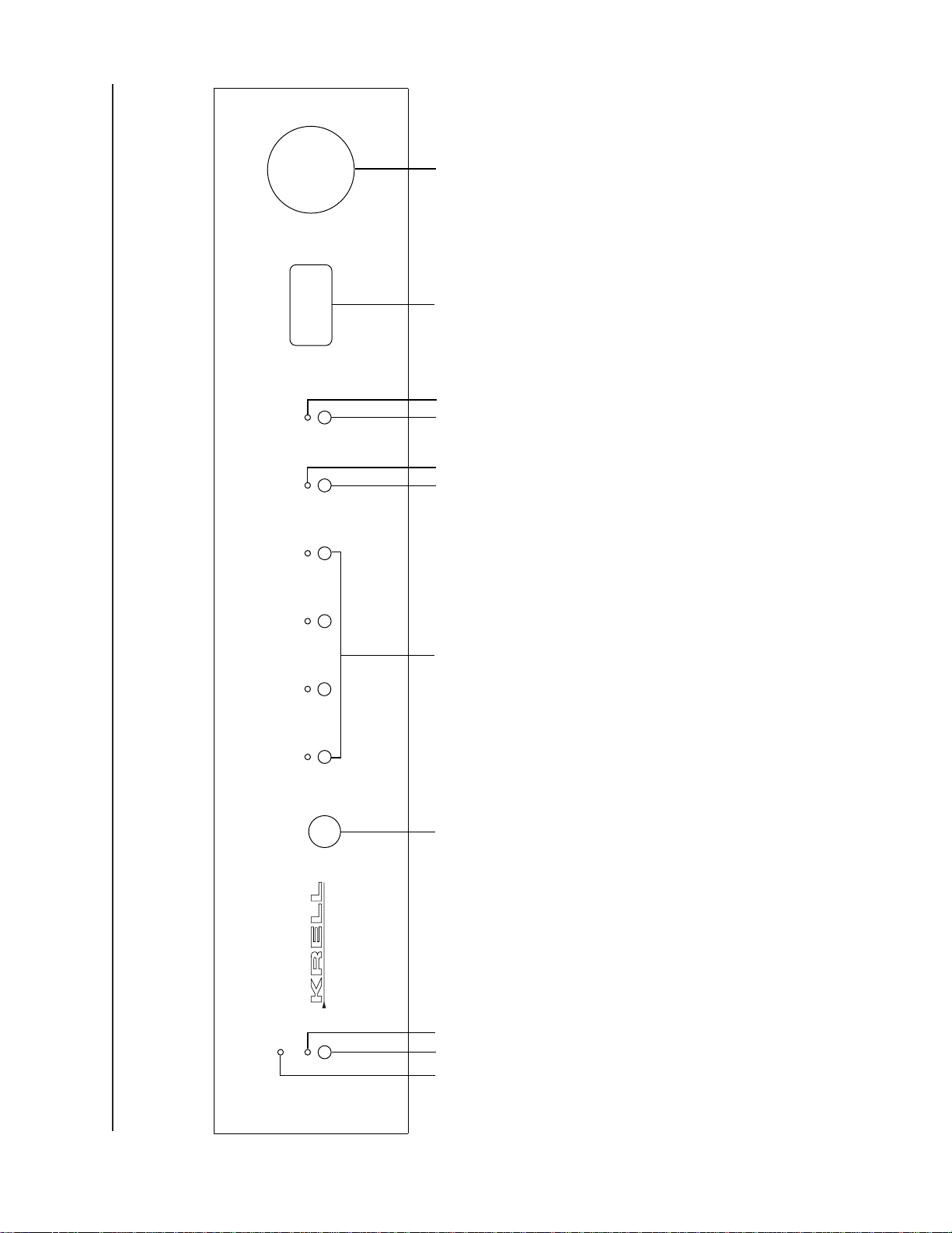
Figure 1 The KAV–280p Front Panel
MUTETAPE
POWER
STAND-BY
KAV–280p
3
1
2
4
5
B–1
S–1
S–2 S–3
7
11
6
9
10
8
Mode Indicators
8 Mute Button
9 Mute LED
Volume Adjustment
Functions
10 Level Knob
11 Front Panel Display
Power
1 Power Button
2 Power LED
3Stand-by LED
4 Infrared Sensor
Analog Devices
5 S-1, S-2, S-3, and
B-1 Buttons and LEDs
6Tape Button
7Tape LED
 Loading...