

Page 1
KAV-250a
Leader in Audio Engineering
Instructions for Use, v 99.2
Stereo Power Amplifier
KAV-250a/3
Three-Channel Power Amplifier
Owner’s Reference
Page 2
KAV-250a Stereo Power Amplifier and
KAV-250a/3 Three-Channel Power Amplifier
Instructions for Use, v 99.2
Cover: KAV-250a/3 Three-Channel Power Amplifier
Krell Industries, Inc.
45 Connair Road
Orange, CT 06477-3650 USA
TEL 203-799-9954
FAX 203-799-9796
E-MAIL krell @ krellonline.com
WEBSITE http://www.krellonline.com
This product complies with the EMC directive (89/336/EEC) and the low-voltage directive
(73/23/EEC).
WARNINGS
The amplifier must be placed on a firm, level surface where it is not exposed to dripping or
splashing.
The ventilation grids on the top of the amplifier and the space underneath the amplifier must be
unobstructed at all times during operation. Do not place flammable material above or beneath
the amplifier.
Contact your authorized Krell dealer, distributor, or Krell before using any devices designed to
alter or stabilize the AC power for the KA V-250a or KA V-250a/3.
Before connecting the KA V-250a or KA V-250a/3, make sure the amplifier is off and any output
device (such as a preamplifier) is in mute or stand-by mode. Make sure all cable terminations
are of the highest quality and free from frayed ends, short circuits, or cold solder joints.
Use only one set of inputs to the amplifier at a time.
After reconfiguring for MAT, do not use more than one input at the same time.
After bridging, do not use both inputs at the same time.
THERE ARE NO USER SERVICEABLE PARTS INSIDE ANY KRELL PRODUCT
Please contact your authorized Krell dealer, distributor, or Krell if you have any questions not
addressed in this reference manual.
This product is manufactured in the United States of America. Krell® is a registered trademark of Krell
Industries, Inc., and is restricted for use by Krell Industries, Inc., its subsidiaries, and authorized agents.
Multi Amp Throughput
TM
is a trademark of Krell Industries, Inc. All other trademarks and tradenames are
registered to their respective companies.
© 1999 by Krell Industries, Inc. All rights reserved P/N: I960101710688
Page 3
Contents
Page
INTRODUCTION ’
DEFINITION OF TERMS
UNPACKING
PLACEMENT
AC Power Guidelines
FRONT PANEL DESCRIPTION: KAV-250a
BACK PANEL DESCRIPTION: KAV-250a
FRONT PANEL DESCRIPTION: KAV-250a/3
BACK PANEL DESCRIPTION: KAV-250a/3
CONNECTING THE KAV-250a or KAV-250aJ3 AMPLIFIER
TO YOUR SYSTEM
Input and Output Connections
OPTIONAL SYSTEM CONFIGURATIONS
Multi Amp Throughput
1
1
2
3
3
5
7
10
12
14
14
15
15
Bridged Operation
Examples of Connection Scenarios
AMPLIFIER OPERATION
On/Off and Operation
AMPLIFIER TROUBLESHOOTING
How to Troubleshoot System Noise
QUESTION AND ANSWER
WARRANTY
RETURN AUTHORIZATION PROCEDURE
SPECIFICATIONS
KAV-250a and KAV-250a/3 Amplifiers iii
20
22
25
25
26
26
28
29
30
27
Page 4
Illustrations
Page
FIGURE 1
FIGURE 2
FIGURE 3
FIGURE 4
FIGURE 5
or Bridged Operation
FIGURE 6 Reconfiguring the KAV-250a/3 for MAT
or Bridged Operation
The KAV-250a Front Panel
The KAV-250a Back Panel
The KAV-250a/3 Front Panel
The KAV-250a/3 Back Panel
Reconfiguring the KAV-250a for MAT
4
6
9
11
16
19
iv KAV-250a and KAV-250a/3 Amplifiers
Page 5
Introduction
Thank you for your purchase of the Krell KAV-250a Stereo Power Amplifier or
KAV-250a/3 Three-Channel Power Amplifier..
The KAV-250a and KAV-250aJ3 amplifiers provide substantial two- and three-channel
output power that delivers realistic music production at an exceptional value. These
amplifiers can be customized with a variety of optional system configurations: Multi
Amp Throughput (MAT), bridged operation, and high power mono operation. These
options provide a wider range of power outputs and connection options. Both the KAV-
250a and KAV-250a/3 amplifiers provide balanced and single-ended inputs for
complete compatibility with other components. The KAV-250a and KAV-250a/3
amplifiers can be operated using the 12 VDC trigger for other components. Either
amplifier integrates seamlessly home theater or whole-house systems.
This reference manual contains important information on placement, installation, and
operation of the KAV-250a and KAV-250a/3 amplifiers. Please read this information
carefully. A thorough understanding of these details helps ensure satisfactory operation
and long life for your KAV-250a or KAV-250aJ3 amplifier and related system
components.
Definition of Terms
Multi Amp Throughput
An internal connection option that sends the same music signal to all amplifier channels
using one balanced or single-ended connection. MAT reduces installation complexity
and cabling requirements in systems containing multiple amplifiers. MAT also allows a
variety of connection scenarios, including powering loudspeakers that have two sets of
binding posts and independently powering multiple pairs of stereo loudspeakers to
extend the listening environment throughout your home.
Bridging
An internal connection option that links two amplifier channels to operate as one
combined amplifier channel, greatly increasing the channel’s power output.
On
When the power button on the front panel is pressed and the blue power LED
illuminates, the amplifier is on and ready to play music.
Off
When the power button on the front panel is pressed and the blue power LED turns off,
the amplifier is off.
KAV-250a and KAV-250a/3 Amplifiers 1
Page 6
Unpacking
Open the shipping box, which contains:
1 amplifier unit (packed in foam end-caps)
2 ribbon connection cables
KAV-250a fuses:
2 AGC-8 (~ ’amp)
1 slow-blow (20 amp for 100/120 V or 12 amp for 220/240 V)
or
KAV-250a/3 fuses:
3 AGC-.8 ~ amp)
1 slow-blow (20 amp for 100/120 V or 12 amp for 220/240 V)
1 12 VDC output (12 V trigger) cable
1 IEC connector (AC power) cord
1 T-15 Torx wrench
1 packet containing the owner’s reference manual and the warranty registration
card.
Grasp the underside of the foam end-caps that encase the amplifier and lift the
amplifier straight out of the shipping box.
Place the amplifier in a safe location and remove the protective plastic wrapping.
Notes
If any of these items are not included in the shipping box, please contact your
authorized Krell dealer, distributor, or Krell for assistance.
Save all packing materials. If you ship your amplifier in the future, repack the unit in its
original packaging to prevent trans# damage. See Return Authorization Procedure,
on page 29, for more information.
2
KAV-250a and KAV-250aJ3 Amplifiers
Page 7
Placement
Before you integrate the KAV-250a or KAV-250a/3 into your system, review the
following guidelines to choose the location for the component. This will facilitate a
clean, trouble-free installation.
The KAV-250a and KAV-250aJ3 require at least two inches (5 cm) of clearance
each side and at least two inches (5 cm) of clearance above the component to provide
adequate ventilation.
Your amplifier does not require any type of special rack or cabinet for installation. For
the dimensions of your amplifier see Specifications, on pages 30 and 31.
Place the amplifier as close to the loudspeakers as possible and keep the speaker
cable length to a minimum. Speaker cable adds impedance to the load the amplifier
must drive, regardless of the cable’s gauge. Krell amplifiers drive the lowest
impedances with ease, but long speaker cables reduce the maximum power that is
delivered to the loudspeakers.
AC POWER GUIDELINES
Krell recommends operating each amplifier from a dedicated 15-amp AC power line.
For maximum power output, operate the KAV-250a or KAV-250a/3 amplifier from a
dedicated 20-amp AC power line.
KAV-250a and KAV-250a/3 Amplifiers
3
Page 8
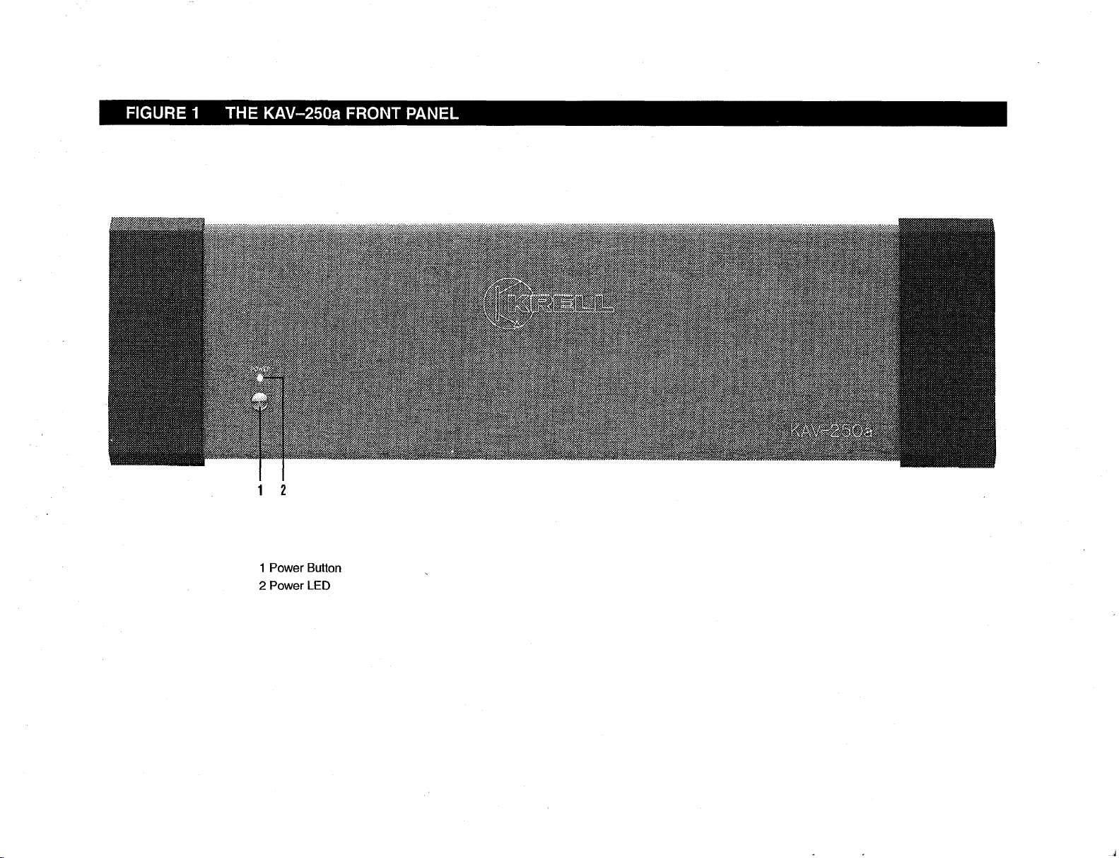
FIGURE 1 THE KAV-250a FRONT PANEL
1 2
1 Power Button
2 Power LED
Page 9
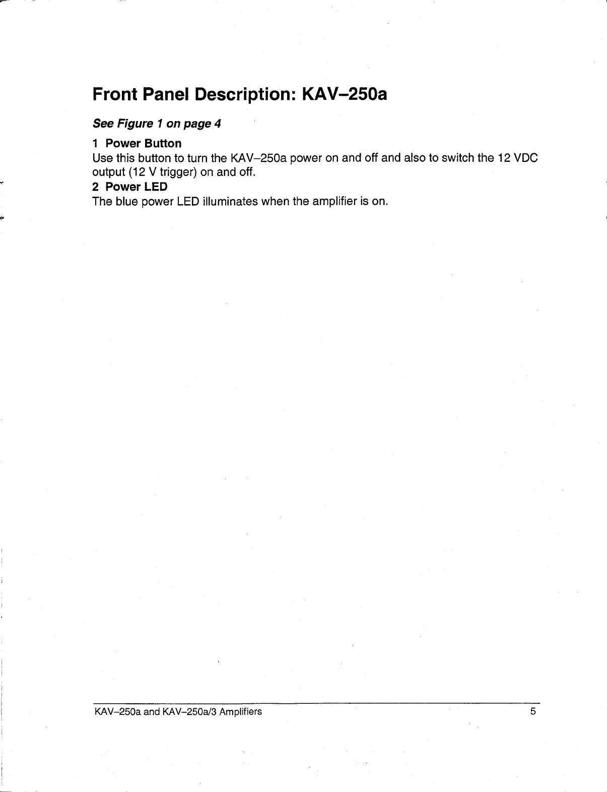
Front Panel Description: KAV-250a
See Figure 1 on page 4
1 Power Button
Use this button to turn the KAV-250a power on and off and also to switch the 12 VDC
output (12 V trigger) on and off.
2 Power LED
The blue power LED illuminates when the amplifier is on.
KAV-250a and KAV-250a/3 Amplifiers 5
Page 10
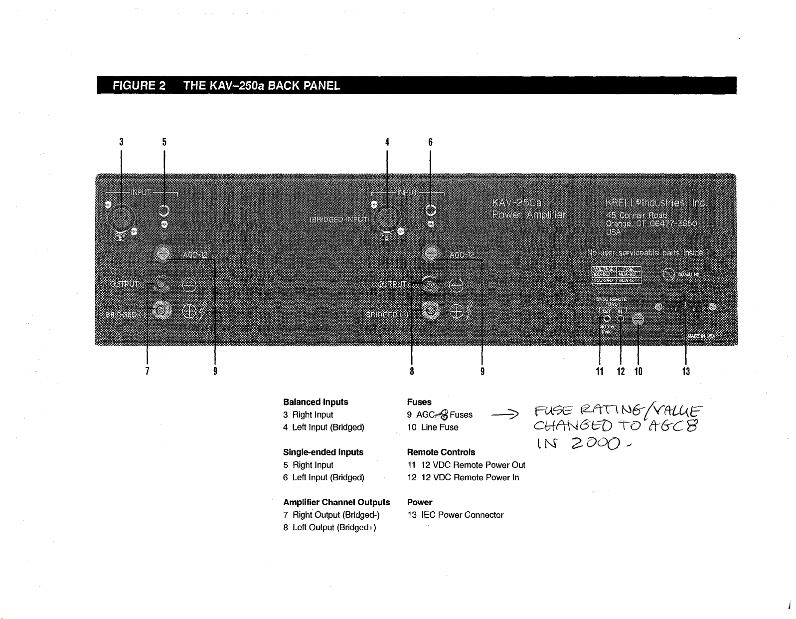
FIGURE 2 THE KAV-250a BA(;K PANEL
5
11 12 10 13
Balanced Inputs
3 Right Input
4 Left Input (Bridged)
Single-ended Inputs
5 Right Input
6 Left Input (Bridged)
Amplifier Channel Outputs
7 Right Output (Bridged-)
8 Left Output (Bridged+)
Fuses
9 AGC~ Fuses
10 Line Fuse
Remote Controls
11 12 VDC Remote Power Out
12 12 VDC Remote Power In
Power
13 IEC Power Connector
Page 11
Back Panel Description: KAV-250a
See Figure 2 on page 6
The KAV-250a back panel provides connections for all inputs and outputs, remote
control input and output links, and AC power supply. Inputs and outputs labeled left and
right are on the left and right side of the amplifier, respectively, when viewing the
amplifier from the front panel.
Balanced Inputs
3, 4 Inputs
These are the right (3) and the left (4) KAV-250a channel inputs for output devices
balanced XLR connectors.
Single-ended Inputs
5,6 Inputs
These are the right (5) and the left (6) KAV-250a channel inputs for output devices
single-ended RCA connectors.
The left balanced or single-ended inputs are used for bridged operation. See
Reconfiguring the KA V-250a for Bridged Operation, on page 20.
Amplifier Channel Outputs
7 Output Bridged(-)
8 Output Bridged(+)
These are the right (7) and left (8) KAV-250a amplifier channel outputs with five-way
loudspeaker binding posts. The loudspeaker binding post terminals accept spade lugs,
bare wire, banana plugs, or pins. Use the red terminal for the positive connection and
the black terminal for the.negative connection. For information on loudspeaker
connections for bridged operation, see Reconfiguring the lEA V-250a for Bridged
Operation, on page 20.
Fuses
9 AGC-12 Fuses
The AGC 12 Volt loudspeaker fuses protect the KAV-250a against short circuits in
loudspeaker output.
10 Line Fuse
The line fuse protects the KAV-250a against short circuits in internal power supplies.
Note
Fuses must be replaced with the fuse value specified on the KA V-250a back panel. Use
a 20 amp slow-blow line fuse for 100/120 V systems or a 12 amp slow-blow line fuse for
220/240 V systems.
KAV-250a and KAV-250a/3 Amplifiers 7
Page 12

Back Panel Description, continued
Remote Controls
11 12 VDC Remote Power Out
12 12 VDC Remote Power In
The KAV-250a is equipped with an output that sends 12 VDC power on/off (12
trigger) signals to other Krell components and other devices that incorporate
12 V trigger. This allows you to turn the KAV-250a on and off using a Krell or other
component in a custom installation.
Notes
12 VDC Out/in (12 V trigger) remote power is limited to 30 ma.
Consult the owner’s manual of any component used in a custom installation to take full
advantage of the KA V-250a remote capability.
Power Supply
13 IEC Connector
The KAV-250a is equipped with a standard female IEC power connector, for use with
the provided AC power cord,
8
KAV-250a and KAV-250a/3 Amplifiers
Page 13
FIGURE 3
THE KAV-250a/3 FRONT PANEL
14 15
14 Power Button
15 Power LED
Page 14

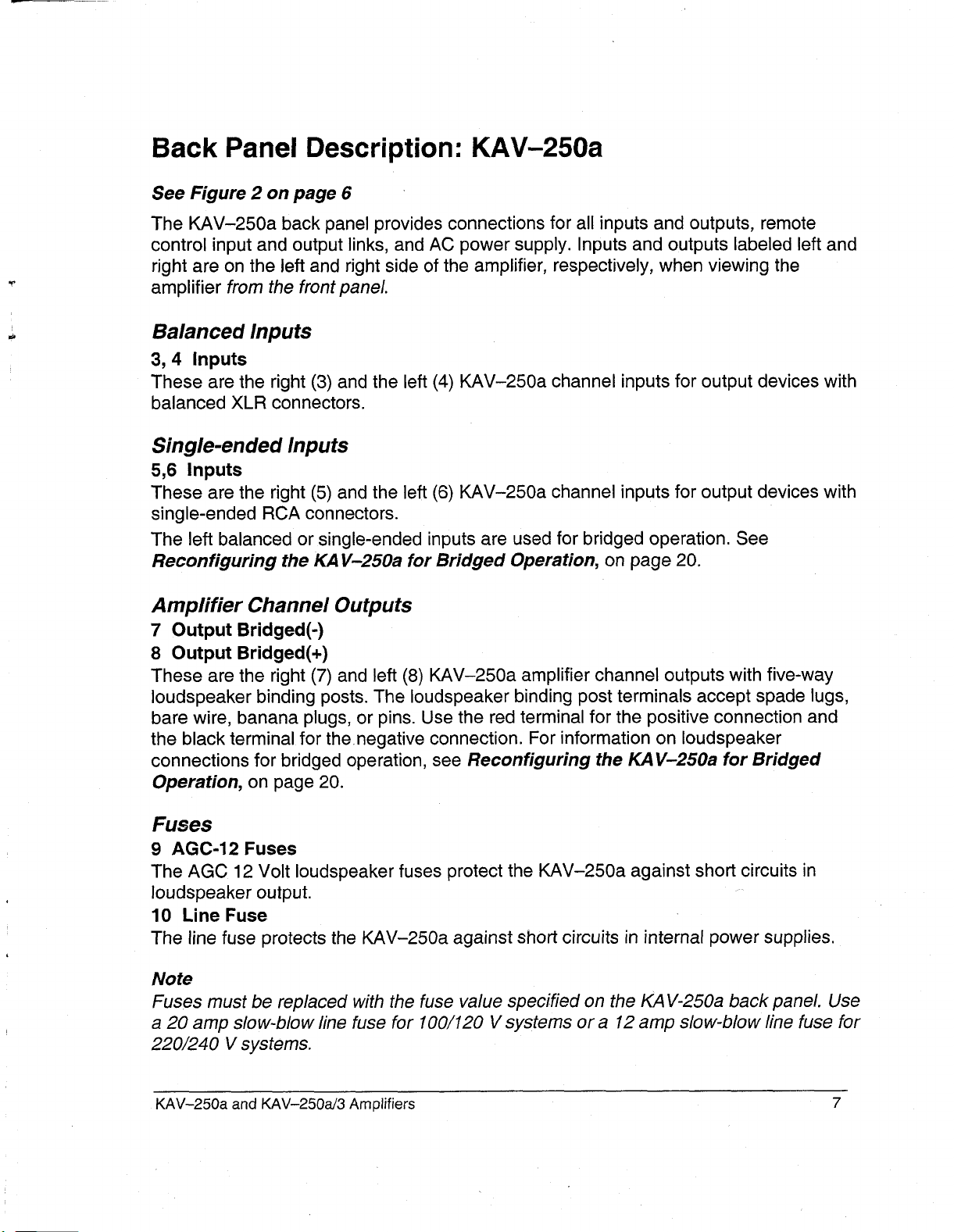
Front Panel Description: KAV-250a/3
See Figure 3 on page 9
14 Power Button
Use this button to turn the KAV-250a/3 power on and off and also to switch the 12 VDC
output (12 V trigger) on and off.
15 Power LED
The blue power LED illuminates when the amplifier is powered on.
10
KAV-250a and KAV-250a/3 Amplifiers
Page 15

FIGURE 4
THE KAV-250a/3 BACK PANEL
16 19 17 2o
25 22
25 23 25 24
Balanced Inputs
16 Right Input
17 Center Input
18 Left Input
Single-ended Inputs
19 Right Input
20 Center Input
21 Left Input
Amplifier Channel Outputs
22 Right Output
23 Center Output
24 Left Output
18 21
Fuses
25 AGC e~Euses ~-----’~
26 Line Fuse
Remote Controls
27 12 VDC Remote Power Out
28 12 VDC Remote Power tn
Power
29 IEC Power Connector
27 28 26 29
ZOO0.
Page 16

Back Panel Description: KAV-250a/3
See Figure 4 on page 11
The KAV-250a/3 back panel provides connections for all inputs and outputs, remote
control input and output links, and AC power supply. Inputs and outputs labeled left and
right are on the left and right side of the amplifier, respectively, when viewing the
amplifier from the front panel.
Balanced Inputs
16, 17, 18 Inputs
These are the right (16), center (17), and left (18) KAV-250a/3 channe~ inputs
output devices with balanced XLR connectors.
Single-ended Inputs
19, 20, 21 Inputs
These are the right (19), center (20), and left (21) KAV-250a/3 channel inputs
output devices with single-ended RCA connectors.
Amplifier Channel Outputs
22, 23, 24 Outputs
These are the right (22), center (23), and left (24) KAV-250a/3 amplifier channel
outputs with five-way loudspeaker binding posts. The loudspeaker binding post
terminals accept spade lugs, bare wire, banana plugs, or pins. Use the red terminal for
the positive connection and the black terminal for the negative connection. For
information about loudspeaker connections for bridged operation, see Reconfiguring
the KA V-250aJ’3 for Bridged Operation, on page 21.
Fuses
25 AGC-12 Fuses
The AGC 12 Volt loudspeaker fuses protect the KAV-250a/3 against short circuits in
loudspeaker output.
26 Line Fuse
The line fuse protects the KAV-250a/3 against short circuits in internal power supplies.
12
KAV-250a and KAV-250aJ3 Amplifiers
Page 17

Back Panel Description, continued
Note
Fuses must be replaced with the fuse value specified on the KA V-250a/3 back panel
Use a 20 amp slow-blow line fuse for 100/120 V systems or a 12 amp slow-blow line
fuse for 220/240 V systems.
Remote Controls
27 12 VDC Remote Power Out
28 12 VDC Remote Power In
The KAV-250a/3 is equipped with an output that sends 12 VDC power on/off (12
trigger) signals to other Krell components and other devices that incorporate
12 V trigger. This allows you to turn the KAV-250aJ3 on and off using a Krell or other
component in a custom installation.
Notes
12 VDC Out/In (12 V trigger) remote power is limited to 30 ma.
Consult the owner’s manual of each component used in a custom installation to take full
advantage of the KA V-250a/3 remote capability.
Power Supply
29 IEC Power Connector
The KAV-250a/3 is equipped with a standard female IEC power connector, for use with
the provided AC power cord.
KAV-250a and KAV-250a/3 Amplifiers 13
Page 18

Connecting the KAV-250a or KAV-250a/3
Amplifier to Your System
INPUT AND OUTPUT CONNECTIONS
The following steps describe how to connect cables to the KAV-250a or KAV-250a/3
amplifier.
1. Neatly arrange and organize the wiring to and from the amplifier and all
components. Separate AC wires from audio cables to prevent hum or other
unwanted noise from being introduced into the system.
21 Connect the loudspeaker cables to the KAV-250a amplifier channel output speaker
binding posts (7, 8), or the KAV-250a/3 amplifier channel output speaker binding
posts (22, 23, 24) located on their respective back panels.
The amplifier channel outputs for the KAV-250a and KAV-250a/3 use five-way
loudspeaker binding posts. The loudspeaker binding post terminals accept spade
lugs, bare wire, banana plugs, or pins. Use the red terminal for the positive
connection and the black terminal for the negative connection.
3. Connect the interconnect cables from your output device to the amplifier inputs. The
KAV-250a is equipped with balanced (3, 4) or single-ended (5, 6) inputs and
KAV-250a/3 is equipped with balanced (16, 17, 18) or single-ended (19, 20,
inputs located on their respective back panels. The balanced inputs use three-pin
XLR connectors; the single-ended inputs use RCA connectors.
4. Insert the end of the AC power cord into the IEC power connector on the KAV-250a
(13) or KAV-250a/3 (29) back panel. Insert the other end into the AC wall outlet.
The amplifier is now ready for operation. See Amplifier Operation, on page 25.
The KAV-250a or KAV-250a/3 amplifier is shipped with shorting pins in the XLR
inputs. These pins should remain in the XLR inputs if the amplifier is operating in the
single-ended mode. When the shorting pin is inserted, pins 1 and 3 are shorted
together. Remove the shorting pins to connect the amplifier for balanced operation.
The XLR pin configuration is described below:
Pin 1 Ground
Pin 2 Non-inverting (0
Pin 3 Inverting (180
Krell recommends using balanced interconnect cables. Balanced interconnect cables
not only can minimize sonic loss but are also immune to induced noise, especially with
installations using long cables. Balanced connections have 6 dB more gain than singleended connections. When level matching is critical, keep this gain value in mind.
14
°)
°)
KAV-250a and KAV-250aJ3 Amplifiers
Page 19

Optional System Configurations
The KAV-250a and KAV-250a/3 can be reconfigured for either Multi Amp Throughput
(MAT) or bridged operation.
IMPORTANT
Removing the cover to reconfigure for MA T or for bridged operation is the ONL Y
instance you are authorized to remove the cover of ANY Kre// component without
voiding your Warranty. For more information on product/imitations and restrictions, see
Warranty, on page 28.
Before Reconfiguring for MAT or Bridged Operation
Read the following important safety instructions before you attempt to reconfigure your
amplifier for either MAT or bridged operation:
1. Unplug the power cord. Unplug the AC power cord from both the IEC power
connector of the KAV-250a (13) or KAV-250aJ3 (29) on the back panel, and
the AC outlet.
2. Avoid the power supply. After removing the screws (see instructions below) and
the cover, locate and stay aware of the location of the power supply. Avoid making
contact with that area of the amplifier.
3. Remove jewelry. Rings, necklaces, bracelets, and other pieces of metal jewelry
can conduct an electrical charge. Consider removing them before attempting any
reconfiguration.
4. Always replace cover. Make sure the amplifier’s cover is properly replaced and
secured by the 12 screws before resuming operation.
IMPORTANT
Operating the amplifier without the cover properly replaced and secured may
void your warranty.
MULTI AMP THROUGHPUT
Multi Amp Throughput (MAT), an internal connection option for either the KAV-250a
the KAV-250a/3, lets you send the same music signal to all amplifier channels using
one balanced or single-ended connection. MAT reduces installation complexity and
cabling requirements in systems containing multiple amplifiers.
Inputs and outputs labeled left and right are on the left and right side of the amplifier,
respectively, when viewing the amplifier from the front panel
KAV-250a and KAV-250a/3 Amplifiers 15
Page 20

FIGURE 5 RECONFIGURING THE KAV-250a FOR MAT OR BRIDGED OPERATI( tN
Left Right
PC boards showing
MAT jumper
configuration
PC boards showing
bridged jumper
configuration
Power supply
Left
Right
PC boards
Right
16 KAV-250a and KAV-250-a/3 Amplifiers
Page 21

Reconfiguring the KAV-250a for MAT
See Figure 5 on page 16
Tools needed: T-15 Torx wrench and one ribbon connection cable
1. Turn the KAV-250a off by pressing the power button (1) on the front panel. The blue
power LED (2) extinguishes. Unplug the AC power cord from the IEC power
connector (13) on the back panel.
2. Using the T:15 Torx wrench, remove the 12 screws that secure the amplifier cover.
Carefully remove the cover.
Locate the small PC board at the rear of each amplifier channel and jumper pins
3.
labeled J4, J5, and J6.
Connect one end of the ribbon connection cable to jumper pin J4 on the left
4.
amplifier channel (closest to the power supply). The ribbon snaps into place.
Connect the other end of the ribbon connection cable to jumper pin J5 on the right
amplifier channel.
Replace the cover (slide the front panel end in first). Using the T-15 Torx wrench,
5.
secure the 12 screws.
The KAV-250a amplifier is now reconfigured for MAT operation.
Connecting the KAV-250a Reconfigured for MAT
See Figure 2 on page 6
1. Connect your output device to a single-ended or balanced input on the back panel of
the KAV-250a.
2. Connect each amplifier channel output (7, 8) to a separate loudspeaker, using the
positive and negative terminals on the speaker binding posts.
Reconfiguring the KAV-250a/3 for MAT
See Figure 6 on page 19
Tools needed: T-15 Torx wrench and two ribbon connection cables
1. Turn the KAV-250a/3 off by pressing the power button (14) on the front panel. The
blue power LED (15) extinguishes. Unplug the AC power cord from the IEC power
connector (29) on the back panel.
2. Using the T-15 Torx wrench, remove the 12 screws that secure the amplifier cover.
Carefully remove the cover.
Locate the small PC board at the rear of each amplifier channel and jumper pins
3.
labeled J4, J5, and J6.
4. Connect one end of the first ribbon connection cable to jumper pin J4 on the left
amplifier channel (closest to the power supply). The ribbon snaps into place.
Connect the other end of this ribbon connection cable to jumper pin J5 on the center
amplifier channel.
KAV-250a and KAV-250a/3 Amplifiers 17
Page 22

5. Connect one end of the second ribbon connection cable to jumper pin J4 on the
center amplifier channel. Connect the other end of this ribbon connection cable to
jumper pin J5 on the right amplifier channel.
Replace the cover (slide the front panel end in first). Using the T-15 Torx wrench,
6.
secure the 12 screws.
The KAV-250a/3 amplifier is now reconfigured for MAT operation.
Connecting the KAV-250a/3 Reconfigured for MAT
See Figure 4 on page 11
1. Connect your output device to a single-ended or balanced input on the back panel of
the KAV-250a/3.
2. Connect each amplifier channel output (22, 23, 24) to a separate loudspeaker, using
the positive and negative terminals on the speaker binding posts.
18
KAV-250a and KAV-250a/3 Amplifiers
Page 23

FIGURE 6 RECONFIGURING THE KAV-250a/3 FOR MAT OR BRIDGED OPERATION
Left Center Right
PC boards showing
MAT jumper
configuration
PC boards showing
bridged jumper
configuration
(See Option 1,
on page 21)
PC boards showing
bridged jumper
configuration
(See Option 2,
on page 21)
Power supply
KAV-250a and KAV-250-a/3 Amplifiers
PC boards
ht
19
Page 24

BRIDGED OPERATION
The KAV-250a and the KAV-250a/3 can be reconfigured for bridged operation. When
the KAV-250a amplifier’s channels are bridged, the amplifier’s output power is
quadrupled: the amplifier delivers 1,000 Watts to an 8 Ohm load. The KAV-250a/3 can
be reconfigured to bridge any two of its three amplifier channels to operate as one
combined amplifier channel. When using the bridged amplifier channel only, the
KAV-250a/3 delivers 1,000 Watts to an 8 Ohm load.
Inputs and outputs labeled left and right are on the left and right side of the amplifier,
respectively, when viewing the amplifier from the front panel
Reconfiguring the KAV-250a for Bridged Operation
See Figure 5 on page 16
Tools needed: T-15 Torx wrench and one ribbon connection cable
Turn the KAV-250a off by pressing the power button (1) on the front panel. The blue
1.
power LED (2) extinguishes. Unplug the AC power cord from the IEC power
connector (13) on the back panel.
2. Using the T-15 Torx wrench, remove the 12 screws that secure the amplifier cover.
Carefully remove the cover.
Locate the small PC board at the rear of each amplifier channel and jumper pins
3.
labeled J4, J5, and J6.
Connect one end of the ribbon connection cable to jumper pin J4 on the left
4.
amplifier channel (closest to the power supply). The cable snaps into place. Connect
the other end of the ribbon connection cable to jumper pin J6 on the right amplifier
channel.
Replace cover (slide front panel end in first). Using the T-15 Torx wrench, secure
5.
the 12 screws.
The KAV-250a amplifier is now ready for bridged operation.
Connecting the Bridged KAV-250a
See Figure 2 on page 6
1. Connect the output cable from the output device to the balanced XLR (4/ or the
single-ended RCA (6) inputs connectors marked (BRIDGED ~NPUT).
2. Connect the positive loudspeaker lead (red) to the positive binding post on the left
amplifier channel output (8), marked BRIDGED (+). Connect the negative loudspeaker
lead (black) to the positive binding post on the right amplifier channel (7), marked
BRIDGED (-).
20
KAV-250a and KAV-250a/3 Amplifiers
Page 25

IMPORTANT
When operating the amplifier in bridged mode and using an output device with
single-ended RCA cables, be sure to remove the shorting pin from the/eft balanced
XLR input (4).
Reconfiguring the KAV-250a/3 for Bridged Operation
See Figure 6 on page 19
Tools needed: T-15 Torx wrench and two ribbon connection cables
1. Turn the KAV-250a/3 off by pressing the power button (14) on the front panel. The
blue power LED (15) extinguishes. Unplug the AC power cord from the IEC power
connector (29) on the back panel.
2. Using the T-15 Torx wrench, remove the 12 screws that secure the amplifier cover.
Carefully remove the cover.
Locate the small PC board at the rear of each amplifier channel and jumper pins
3.
labeled J4, J5, and J6.
Option 1: To bridge left and center amplifier channels, connect one end of the
4.
ribbon connection cable to jumper pin J4 on the left amplifier channel (closest to the
power supply). The cable snaps into place. Connect the other end of the ribbon
connection cable to jumper pin J6 on the center amplifier channel.
Option 2: To bridge center and right amplifier channels, connect one end of the
ribbon connection cable to jumper pin J4 on the center amplifier channel. Connect
the other end of the ribbon connection cable to jumper pin J6 on the right amplifier
channel.
Replace cover (slide the front panel end in first). Using the T-15 Torx wrench,
5.
secure the 12 screws.
The KAV-250aJ3 amplifier is now ready for bridged operation.
Connecting the Bridged KAV-250a/3
See Figure 4 on page 11
When the left and center amplifier channels are bridged (Option 1), connect the
1.
output cable from the output device to the center balanced XLR (17) or single-ended
RCA (20) input.
Connect the positive loudspeaker lead (red) to the positive binding post on the
center amplifier channel (23). Connect the negative loudspeaker lead (black) to
positive binding post of the left amplifier channel (24).
KAV-250a and KAV-250a/3 Amplifiers 21
Page 26

2. When the center and right amplifier channels are bridged (Option 2), connect the
output cable from the output device to the right balanced XLR (16) or single-ended
RCA (19)input.
Connect the positive loudspeaker lead (red) to the positive binding post on the
(right) amplifier channel (22). Connect the negative loudspeaker lead (black)
positive binding post of the center amplifier channel (23).
The remaining channel may be connected for normal operation.
IMPORTANT
When operating the amplifier in bridged mode and using an output device with a
single-ended RCA cable, be sure to remove the shorting pin from the balanced XLR
input.
EXAMPLES OF CONNECTION SCENARIOS
High Power Mono Operation
High power mono operation uses two KAV-250a bridged amplifiers: one amplifier is
dedicated to the left loudspeaker and one amplifier is dedicated to the right
loudspeaker. Additional loudspeakers in a home theater system may be connected in
this way by using additional KAV-250a amplifiers. The diagram below illustrates
connecting a system for high power mono operation:
22
KAV-250a and KAV-250a/3 Amplifiers
Page 27

Examples of Connection Scenarios, continued
Power Biamplification (Stereo, 2-channel)
Power biamplification uses the MAT feature of the KAV-250a to send the same music
signal to all amplifier channels using one balanced or single-ended input connection.
When the KAV-250a is reconfigured for MAT, one channel of the amplifier powers the
Ioudspeaker’s high frequency end, and the other channel powers the Ioudspeaker’s low
frequency end. This connection scenario is used only with loudspeakers that feature
two sets of binding posts. For more information, consult the owner’s reference for your
loudspeakers. The diagram below illustrates connecting a system for power
biamplification:
KAV-250a and KAV-250aJ’3 Amplifiers
23
Page 28

Examples of Connection Scenarios, continued
Multi Power Mode
Multi power mode uses the KAV-250a/3’s MAT feature to independently power multiple
pairs of stereo loudspeakers to extend the listening environment throughout your home.
When the KAV-250a/3 is reconfigured for MAT, each channel powers an individual
loudspeaker, with one KAV-250a/3 dedicated to driving outputs to the left loudspeakers
and one KAV-250a/3 driving outputs to the right loudspeakers. The diagram below
illustrates connecting a system for multi power mode:
24 KAV-250a and KAV-250aJ3 Amplifiers
Page 29

Amplifier Operation
ON/OFF AND OPERATION
When powering up your system, turn amplifiers on last. When powering down your
system, turn amplifiers off first. The procedures for amplifier operation follow.
1. Press the KAV-250a power button (1) or KAV-250a/3 power button (14) on
amplifier’s front panel. Wait until the blue power LED (2) on the KAV-250a or (15)
on the KAV-250a/3 illuminates and you hear a click. The amplifier is now ready for
operation.
2. With the output device muted or volume control fully lowered, select an output
device. Decrease or increase the volume control to the desired listening level.
3. Before turning the system off, mute or lower the output device volume. Press the
front panel power button to turn the amplifier off. It is now safe to turn off the rest of
the system.
IMPORTANT
Always turn off the amplifier before changing input connections, and mute or fully
attenuate the preamplifier level when switching sources.
These amplifiers have tremendous reserves of power and safely drive loudspeakers to
extremely high sound pressure levels. However, use care when setting high playback
levels and lower the volume level at any sign of loudspeaker distress.
KAV-250a and KAV-250a/3 Amplifiers
25
Page 30

Amplifier Troubleshooting
HOW TO TROUBLESHOOT SYSTEM NOISE
When you mix and match audio components, each with its own ground potential, a low
frequency hum may occur in one or both loudspeakers. This often occurs when
introducing a new component into a system.
If a low frequency hum emanates from the loudspeakers when you place the KAV-
250a stereo or KAV-250a/3 three-channel amplifier into your system, follow these
simple troubleshooting steps.
Check all input and output connections, making sure they are of sound construction.
1,
2. With the amplifier off, remove the interconnect cables, then press the KAV-250a
power button (1) or KAV-250a/3 power button (14) to turn the amplifier
If the hum disappears, press the power button again to turn the amplifier off and
3.
reinsert one of the interconnect cables.
Turn the amplifier back on. If the hum reappears with one or both interconnect
4.
cables inserted, there may be a defective cable. Have the interconnect cables
checked before proceeding.
If the interconnect cables are sound, you may be experiencing a ground loop. This can
often be easily eliminated. Please contact your authorized Krell dealer, distributor, or
Krell for suggestions on how to solve this problem.
26
KAV-250a and KAV-250a/3 Amplifiers
Page 31

Question and Answer
Q. Should I leave the KAV-250a or KAV-250a/3 amplifier on at all times?
A. No. These amplifiers do not have a stand-by mode. Leaving them on at all times
would result in considerable heat output and power consumption. For best results, turn
the amplifier off when not in use, and allow a five minute warm-up after it is turned on.
See Amplifier Operation, on page 25.
Qo When I turn the amplifier on there is a loud hum through the loudspeakers. What
should I do?
A. When a new component is introduced, a low frequency hum may occur in one or
both loudspeakers. Check all input and output connections and cables, making sure
they are of sound construction. See How to Troubleshoot System Noise, on page 26.
If the connections and cables are sound, you may be experiencing a ground loop. This
can often be easily eliminated. Please contact your authorized Krell dealer, distributor,
or Krell for suggestions on how to solve this problem.
Q. When I connect the amplifier to my system using the single-ended inputs, a loud
buzz comes from my loudspeakers. Is the amplifier broken?
A. Check that the shorting pins for the KAV-250a or KAV-250a/3 are inserted into the
XLR inputs (the unit is shipped with the pins in place). When using the single-ended
inputs, these shorting pins must be inserted between pins 1 and 3 to keep external
noise from corrupting the signal. For more information, see Connecting the KAV-250a
or KA V-250a/3 Amplifier to Your System, on page 14.
KAV-250a and KAV-250a/3 Am plifiers 27
Page 32

Warranty
The KAV-250a and KAV-250a/3 amplifiers have. a limited
and transferable warranty of five years for parts and labor
on cimuitry. Should this product fail to perform at any time
during the warranty, Krell will repair it at no cost to the
owner, except as set forth in this warranty.
This warranty does not apply to damage caused by acts of
God or nature.
The warranty described on this page shall be in lieu of any
other warranty, expressed or implied, including, but not limited to, any implied warranty of merchantability or fitness for
a particular purpose. There are no warranties which exceed
beyond those described in this document. If this product
does not perform as warranted herein, the owner’s sole
remedy shall be repair. In no event will Krell be liable for incidental or consequential damages arising from purchase,
use, or inability to use this product, even if Krell has been
advised of the possibility of such damages.
The warranty pedod begins on the date of retail purchase,
as noted on the retail sales slip provided by an authorized
Krell dealer or distributor, or on the warranty registration
card sent to Krell. In the event adequate proof of purchase
date is unavailable, the warranty pedod will begin on the
date the unit was originally shipped from the factory. Krell
can determine the original ship date from the serial number.
Transfer of warranty to a second owner occurs auto-
matically. Please contact Krell to have the registration on the
warranty changed. When the warranty is transferred, any
successive owner assumes the remainder of the odginal
warranty period.
The warranty for Krell products is valid only in the country to
which they were originally shipped, through the authorized
Krell distributor for that country, and at the factory. There
may be restrictions on or changes to Krell’s warranty
because of regulations within a specific country. Please
check with your distributor for a complete understanding of
the warranty in your country.
If a unit is serviced by a distributor who did not import the
unit, there may be a charge for service, even if the product
is within the warranty period.
Freight to the factory is your responsibility. Return freight
within the United States (U.S.A.) is included in the warranty.
If you have purchased your Krell product outside the U.S.A.
and wish to have it serviced at the factory, all freight and
associated charges to the factory are your responsibility.
Krell will pay return freight to the U.S.A.-based freight forwarder of your choice. Freight and other charges to ship the
unit from the freight forwarder to you are also your responsibility.
Krell is not responsible for any damage incurred in transit.
Krell will file claims for damages as necessary for units damaged in transit to the factory. You are responsible for filing
claims for shipping damages during the return shipment.
Krell does not supply replacement parts and/or products to
the owner of the unit. Replacement parts and/or products
will be furnished only to the distribtuor performing service on
this unit on an exchange basis only; any parts and/or prod-
ucts returned to Krell for exchange become the property of
Krell.
No expressed or implied warranty is made for any Krell
product damaged by accident, abuse, misuse, natural or
personal disaster, or unauthorized modification.
Any unauthorized voltage conversion, disassembly,
component replacement, perforation of chassis,
updates, or modifications performed to the unit will
void the warranty.
The operating voltage of this unit is determined by the factory and can only be changed by an authorized Krell distrib-
utor or at the factory. The voltage for this product in the
U.S.A. cannot be changed until six months from the original
purchase date.
In the event that Krel] receives a product for warranty ser-
vice that has been modified in any way without Krell authorization, all warranties on that product will be void. The prod-
uct will be returned to original factory layout Sl~ecifications at
the owner’s expense before it is repaired. All repairs
required after the product has been retumed to odginal fac-
tory specifications will be charged to the customer, at cur-
rent parts and labor rates.
All operational features, functions, and specifications and
policies are subject to change without notification.
To register your product for warranty benefits,
complete and return the Warranty
Registration Card enclosed in the shipping
box within 15 days of purchase. Thank you.
28 KAV-250a and KAV-250a/3 Amplifiers
Page 33

Return Authorization
Procedure
If you believe there is a problem with your
component, please contact your dealer, dis-
tributor, or the Krell factory to discuss the
problem before you return the component for
repair. To expedite service, you may wish to
complete and e-mail the Service Request
Form in the Service Section of our website
at:
http://www.krellonline.com
To return this product to Krell, please
follow this procedure so that we may
serve you better:
1. Obtain a Return Authorization Number
(R/A number) and shipping address
from the Krell Service Department.
Insure and accept all liability for loss of
2.
or damage to this product during ship-
ment to the Krell factory and prepay all
shipping charges. Please see the
Warranty page in this manual, concerning liability for shipping damage and
shipping charges.
To contact the Krell Service Department
TEL 203-799-9954
Monday-Friday
9:00 AM to 5:00 PM EST
FAX 203-799-9796
E-MAIL service@ krellonline.com
WEBSITE http://www.krellonline.com
PRODUCT NAME SERIAL NUMBER
This product may also be hand delivered if
arrangements with the Service Department
have been made in advance. Proof of pur-
chase will be required for warranty validation at the time of hand delivery.
IMPORTANT
Use the original packaging to ensure safe
transit of this product to the dealer, distributor, or factory. Krell may, at its discretion,
return this product in new packaging and bill
the owner for such packaging if the product
received by Krell was boxed in non-stan-
dard packaging or if the original packaging
was so damaged that it was unusable. If
Krell determines that new packaging is
required, the owner will be notified before
this product is returned.
To purchase additional packaging, please
contact your authorized Krell dealer, distrib-
utor, or the Krell Service Department.
29
KAV-250a and KAV-250a/3 Amplifiers
Page 34

Specifications
KAV-250a Stereo Amplifier
FREQUENCY RESPONSE
SIGNAL TO NOISE RATIO
"A" WEIGHTED
TOTAL HARMONIC DISTORTION (THD)
GAIN
INPUT IMPEDANCE
INPUT SENSITIVITY
OUTPUT VOLTAGE
OUTPUT POWER, EACH CHANNEL
DRIVEN
BRIDGED
POWER CONSUMPTION
20 Hz to 20 kHz +0 dB, -0.1 dB
0.4 Hz to 170 kHz +0 dB, -3 dB
118dB
1 kHz < 0.06%
20 kHz < 0.25%
26.4 dB
100 kOhms
2.15 Vrms
Peak to Peak
RMS
8 Ohms
4 Ohms
8 Ohms
Idle
138 V
49 V
250 W
500 W
1,000 W
210W
INPUTS
OUTPUTS
DIMENSIONS
WEIGHT
30
Max.
1 pair single-ended via RCA connectors
1 pair balanced via XLR connectors
1 pair amplifier channels via five-way speaker
binding posts
19w x 6.3h x 15.3d in.
48.3w x 16h x 38.9d cm
Shipping 50 lb., 22.7 kg
Unit only 43 lb., 19.5 kg
KAV-250a and KAV-250a/3 Amplifiers
1,850 W
Page 35

KAV-250a/3 Three-Channel Amplifier
FREQUENCY RESPONSE
SIGNAL TO NOISE RATIO
"A" WEIGHTED
TOTAL HARMONIC DISTORTION (THD)
GAIN
INPUT IMPEDANCE
INPUT SENSITIVITY
OUTPUT VOLTAGE
OUTPUT POWER, EACH CHANNEL
DRIVEN
BRIDGED
POWER CONSUMPTION
20 Hz to 20 kHz
0.4 Hz to 112 kHz
118dB
1 kHz < 0.06%
20 kHz < 0.25%
26.4 dB
100 kOhms
2.15 Vrms
Peak to Peak
RMS
8 Ohms
4 Ohms
8 Ohms
Idle
138 V
250 W
500 W
1,000 W
235 W
+0 dB, -0.2 dB
+0 dB, -3 dB
49 V
Max.
INPUTS
OUTPUTS
DIMENSIONS
WEIGHT
All operational features, functions, specifications, and policies are subject to change without
notification.
3 single-ended via RCA connectors
3 balanced via XLR connectors
3 amplifier channels via five-way speaker
binding posts
19w x 6.3h x 15.8d in.
48.3w x 16h x 40.1d cm
Shipping 60 lb., 27.2 kg
Unit only 52 lb., 23.5 kg
1,930 W
KAV-250a and KAV-250a/3 Amplifiers
31
Page 36

Krell Industries, Inc.
45 Connair Road
Orange, CT 06477-3650 USA
KAV-250a
Stereo Power Amplifier
TEL 203-799-9954
FAX 203-799-9796
E-MAIL krell@ krellonline.com
WEBSITE http://www.krellon line.corn
KAV-250a/3
Three-Channel Power Amplifier
 Loading...