

US ER IN ST RU CT IO NS
FOR MODELS: 278424 (12 Volt Batteries only)
THIS MANUAL CONTAINS IMPORTANT SAFETY AND OPERATING INSTRUCTIONS.
PLEASE KEEP IT SAFE FOR REFERENCE.
CONDITIONER • CHARGER • MAINTAINER
CONDITIONER • CHARGER • MAINTAINER
US ER IN ST RU CT IO NS
In the interests of product improvement we
reserve the right to make technical an d
design changes with out notice.
kree-instructions-A5-v08:Layout 1 26/7/11 15:47 Page 1
SAFETY NOTICE:
WARNING – RISK OF EXPLOSIVE GASES. Batteries generate explosive gases during
normal operation. To avoid risk of injury always observe the following safety notices.
1. To reduce risk of a Battery explosion, follow these instructions and those marked on the Battery or in
the vehicle manual.
2. Always ensure that charging takes place in a well ventilated area.
3. NEVER smoke or allow an open spark or flame to occur in the vicinity of the Battery or engine.
4. Always connect the output (DC) leads to the Battery BEFORE connecting the electric supply.
5. Always use KREE recommended accessories. The use of third party accessories may result in injury
to persons and damage to property.
6. To reduce risk of damage to the AC plug and lead remove the AC lead from the AC supply by
gripping the plug not the lead.
7. Ensure the Charger leads are located so that they cannot be stepped on, tripped over, or otherwise
subjected to damage or stress.
8. Check that the Battery voltage matches the 12V Battery Charger output voltage.
9. To reduce risk of electric shock, unplug the Charger from the AC supply before attempting any
maintenance or cleaning.
10. Use the Charger for charging rechargeable automotive batteries ONLY. It is not intended to supply
power to an electrical system or to charge dry-cell batteries. Charging dry-cell batteries may result in
explosion and cause injury to persons and damage to property.
11. NEVER charge a frozen Battery.
PERSONAL PRECAUTIONS:
1. Have plenty of fresh water and soap nearby in case battery acid contacts skin, clothing or eyes.
2. Wear complete eye and clothing protection.
3. Avoid touching eyes while working with batteries.
4. If battery acid contacts skin or clothing wash immediately with soap and water. If acid enters an eye,
immediately flood eye with running cold water for at least 10 minutes and seek immediate
medical attention.
5. Take care not to drop metal objects onto the Battery terminals which could create sparks or a
short-circuit.
6. Remove personal metal items such as rings, bracelets, necklaces and watches. Batteries can deliver
a current sufficient to weld a ring or the like to metal causing a severe burn.
PREPARING TO CHARGE:
1. Check that the Battery Charger output voltage matches the Battery voltage.
2. If necessary remove the Battery from the vehicle ensuring that all accessories on the vehicle are off in
order to prevent sparks.
3. Always remove the grounded terminal from the Battery first.
4. Be sure the area around the Battery is well ventilated while Battery is being charged.
5. Clean Battery terminals taking care to keep corrosion from coming in contact with eyes.
6. Follow the Battery manufacturer’s instructions closely. e.g. Topping up electrolyte, removing or not
removing cell caps while charging, recommended rates of charge, etc.
POSITIONING THE CHARGER:
1. Position the Charger as far away from Battery as the output cable permits.
2. Never place the Charger directly above or below the Battery being charged. Gases or fluids from the
Battery may corrode and damage the Charger.
3. Never allow battery acid to come into contact with the Charger.
4. Always ensure that charging takes place in a well ventilated area.
5. Position all leads to and from the charger to avoid risks of trips, falls or accidental damage.
2 3
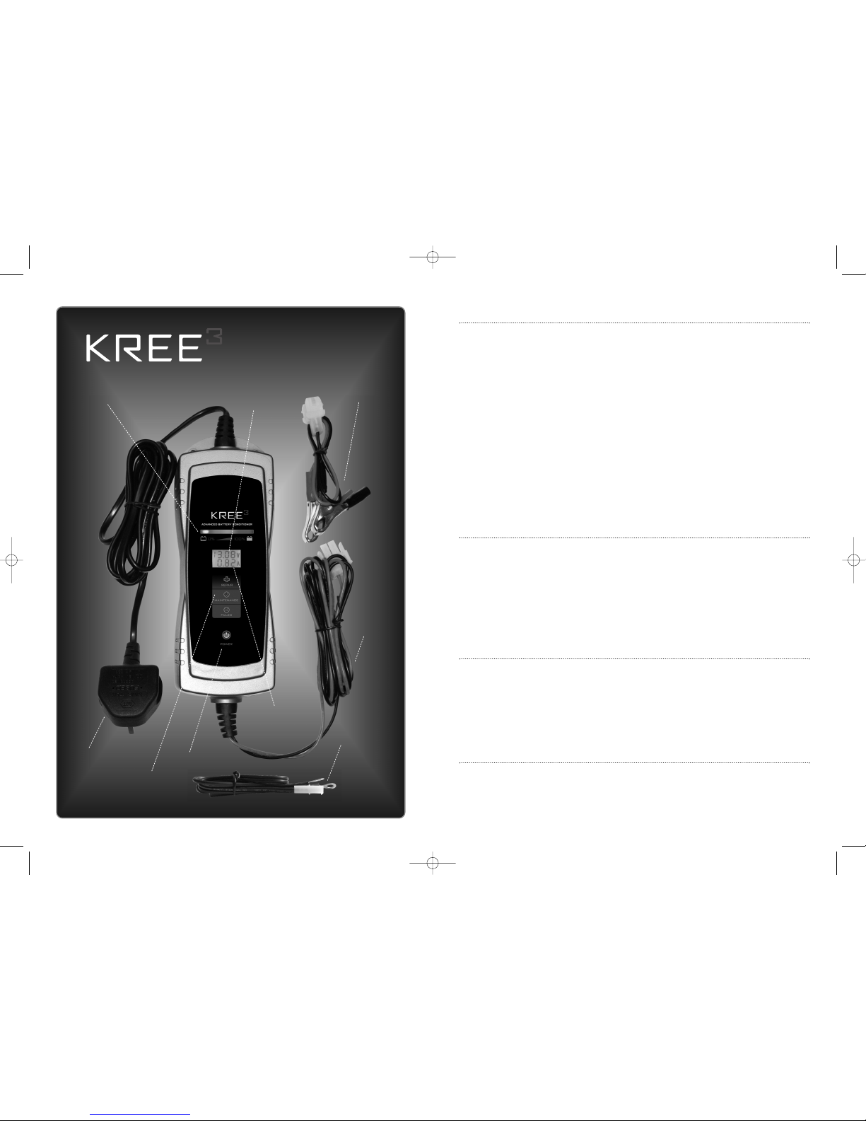
Eyelet
Connection
Crocodile Clip
Connection
Power Indicator
Output
(DC) Lead
Battery Voltage
Indicator
(See page 5)
Charge Current
Indicator
(See page 5)
Input (AC) Lead
Charge
Progress
Bar
LED Charger Status
Indicator (See page 6)
CONDITIONER •CHARGER • MAINTAINER
kree-instructions-A5-v08:Layout 1 26/7/11 15:47 Page 3

CONNECTING THE CHARGER:
NOTE: THE BATTERY CHARGER HAS SPARK FREE CIRCUITRY! The clips will not spark when touched
together. However always connect or disconnect the output leads before plugging into AC power.
KREE supply two methods of connection to the Battery with the Charger. (Other options are available.
See your dealer for more information.)
• Ring Terminal lead for permanent connection to the Battery in the vehicle. This is a convenient way
of connecting the Charger to the vehicle for regular or ongoing maintenance.
• Crocodile clips for charging the Battery outside the vehicle.
1. Follow these steps when Battery is installed in a vehicle and using Crocodile Clips.
a. Double check polarity of Battery terminals. (Red + Positive) (Black – Negative).
b. Determine which terminal of Battery is grounded (connected) to the chassis. If negative terminal
is grounded to the chassis (as in most vehicles), see item (c). If positive terminal is grounded to
the chassis, see item (d).
c. For a negative-grounded vehicle, first connect the positive (red) clip from the Battery Charger to
the positive terminal of Battery. Next connect the negative (black) clip to an unpainted part of
the vehicle chassis, frame or engine block remote from the Battery ensuring a good electrical
contact. Do not connect the clip to the carburetor, fuel lines, or sheet-metal body parts.
d. For a positive-grounded vehicle, connect the negative (black) clip from Battery Charger to
negative terminal of Battery first. Connect the positive (red) clip to an unpainted part of the
vehicle chassis, frame or engine block remote from the Battery ensuring a good electrical
contact. Do not connect the clip to the carburetor, fuel lines, or sheet-metal body parts.
e. Connect Charger supply (AC) lead to a suitable AC supply to commence charging.
f. When disconnecting the Charger, disconnect the electric supply, remove clip from vehicle
chassis, and then remove clip from Battery terminal.
2. Follow these steps when Battery is installed in a vehicle and using Ring Terminal leads.
a. Double check polarity of Battery terminals. (Red + Positive) (Black – Negative).
b. Connect the Ring Terminals to the Battery. (Red + Positive) (Black – Negative) ensuring that the
cable does not impede the normal operation of the vehicle and cannot become damaged.
c. Exit the connector to a point at which it can be conveniently connected to the output (DC) lead
from the Charger and secure if necessary using cable ties or similar.
d. Connect the output (DC) lead from the Charger to the Ring Terminal lead connected to
the Battery.
e. Connect Charger supply (AC) lead to a suitable AC supply to commence charging.
f. When disconnecting the Charger, disconnect the AC supply lead before unplugging the
Charger from the vehicle.
3. Follow these steps when Battery is outside the vehicle using Crocodile Clips.
a. Double check polarity of Battery terminals. (Red + Positive) (Black – Negative).
b. Connect the negative (black) Charger clip to the negative terminal of Battery.
c. Connect the positive (red) Charger clip to the positive terminal of Battery.
d. Connect Charger supply (AC) lead to a suitable AC supply to commence charging.
e. When disconnecting the Charger, always disconnect the AC supply first. Then disconnect the
output (DC) lead in the reverse order of connection.
CHARGER OPERATION:
AUTOMATIC MONITORING – Your new KREE Battery Charger is completely automatic and can be left
connected and powered indefinitely. The Charger output will automatically adjust to the condition and type of
the Battery it is charging. When the Battery is fully charged, the ‘Smiley Face’ will illuminate and the
Charger will switchitself to Maintenance mode automatically monitoring and maintaining the Batteryat full charge.
NOTES:
• Your KREE Battery Conditioner and Maintainer will not commence working unless it senses at least
2V from the Battery.
• It must be correctly connected to the Battery to initiate an output voltage.
• If the Charger output is connected to the Battery in reverse the red light will continue flashing.
Reverse the connection to start the Charger, Red to Positive (+ TO +) and Black to Negative (- TO -).
• Never turn on and off your Battery Charger repeatedly within seconds. Should this occur unplug the
Battery Charger from the AC Supply, wait for one minute and then re-connect the AC supply to
reset the charging cycle.
TIME OF CHARGE:
Your KREE Battery Conditioner and Maintainer in bulk charge mode charges at approximately 0.8 Amps.
To calculate the charge time divide the Amp Hour (Ah) capacity of the Battery by 0.8. For example a 12Ah
Battery will take approximately 15 Hours to charge from flat. e.g. 12/0.8=15. Note that times depend on
the Battery state and are approximate. The Charge Progress Bar is designed to indicate the progress of
the Bulk Charge.
‘FAILED’ BATTERIES:
There are two ways that the Charger will indicate a ‘Failed Battery’.
a. The internal safety circuit of the BATTERY CHARGER must sense more than 2 volts in the
Battery before it will allow the Charger to turn on. If the Battery voltage is 2V or less the Power
Indicator Light will flash to indicate that charging has not been initiated. In most cases batteries
in this state cannot be recovered and must be replaced.
b. If after being charged to capacity the Battery is unable to hold a charge the voltage will drop
over a short period. The Charger will detect this drop and the ‘Failed’ Sad Face will
illuminate indicating that the battery must be replaced.
4 5
ICON on LCD Explanation Description
Battery check & recovery
Battery checks or Recovery Mode
is processing.
No Battery connected
Mains power is connected but the Battery
is not connected.
Error message
1. Bad Battery detected – Replace Battery.
2. Reverse polarity detected - Check the
connection of Battery.
1122..8888VV
Battery voltage indication Battery voltage during charge.
00.. 8800AA
Charge current indication Delivered current during charge.
LCD INDICATIONS:
kree-instructions-A5-v08:Layout 1 26/7/11 15:47 Page 5

6 7
TECHNICAL SPECIFICATIONS:
Model No: .............................................. 278424
Input: ...................................................... 120-240V AC 50/60Hz
Input Cable: ............................................ ~1800mm / H03VV
Output:.................................................... 12VDC 800mA
Output Cables:........................................ ~1800mm / SPT-2
Ring Terminal/Clamp Cable Length: ........ 525mm /18AWG SPT-2
Fuse Protected Cables: .......................... 3.0A
Overcharge Protection:............................ Yes
Reverse Polarity Protection: .................... Yes
Enclosure: .............................................. IP65 rated (Body only)
Accessories:............................................ 1 x 525mm cable lead with crocodile clip
.............................................................. 1 x 525mm cable lead with 6.3mm ring terminals
.............................................................. 1 x Wall mounted hanger
Battery Capacity: .................................... 2 – 40 Ah
LED signal Explanation Description
Power indicator
Mains power attached.
Flashing indicates:
Battery not connected.
Battery voltage < 2V (Dead Battery).
Battery connections reversed.
Repair
Battery checks or Recovery Mode
is processing.
Maintenance
The Battery is fully charged and is being
periodically monitored and charged
automatically as required.
Failed
Not possible to recover Battery.
Replace Battery.
LED INDICATIONS:
9 STAGE BATTERY CARE PROGRAM:
1. Testing:
Battery type and condition is checked prior to charge or recovery. Note: Charge will not be initiated if
Battery is less than 2.0V.
2. Battery Recovery & Check:
Recovery Mode initiates in cases where the Charger detects that the charge voltage has risen
excessively at the beginning of the Testing cycle. Upon successful results from these tests recovery or
normal charge cycle will commence.
3. Soft Start:
Where Battery checks indicate that the Battery cannot accept an immediate bulk charge the Charger
delivers a lower current specific to the Battery as part of the recovery process.
4. Pulse Mode:
Pulse Mode delivers alternating voltages and initiates where Battery checks indicate further recovery
steps are required.
5. Recondition Mode:
Recondition Mode charges at a limited voltage and follows when the Pulse mode is completed. It is
designed to further improve Battery condition before the bulk charge.
6. Bulk Charge:
The Bulk Charge stage delivers constant current to charge the Battery to 80% capacity.
7. Absorption Charge:
Absorption Charge is delivered at constant voltage for the remainder of the charge.
8. Checking:
Battery voltage is periodically checked to ensure it can be retained. Where checks indicate this is not
the case the Battery is classified as ‘Failed’.
9. Maintenance:
Maintenance provides for regular checks and the delivery of a charge specific to the state of the
Battery and its loading.
9 STAGE BATTERY CARE PROGRAM
kree-instructions-A5-v08:Layout 1 26/7/11 15:47 Page 7
 Loading...