

KREBS K2015S, K2015, K3017, K4019 Owner's Manual
K2015S/K2015/K3017/K4019
High-Performance Airless
Sprayer
Owner’s Manual • Notice d’utilisation • Manual del Propietario
Attach the return hose.
Attacher le tuyau de retour.
Fije la manguera de retorno.
Attach the tip.
Attacher la tête de pulvérisation.
Fije la boquilla.
Attach the suction set.
Attacher l'ensemble d'aspiration.
Fije el equipo de succión.
EnglishFrançaisEspañol
1-800-880-0993
Krebs Technical Service
Need help? Call us first for answers fast.
Call toll-free if you have any comments or
problems with this product.
1770 Fernbrook Lane, Minneapolis, MN 55447
Visit us on the world wide web!
Q
uick-start
Easy does it from setup to cleanup:
Printed in the U. S. A.
0902 • Form No. 0512719C
123
456
7
8
9
10
Read all WARNINGS!
Lire toutes les mises en garde!
¡Lea todas las advertencias!
Attach the paint hose.
Attacher le tuyau à fluide.
Fije la manguera de fluido.
Lubricate the packings.
Lubrifier les garnitures.
Lubrique las empaquetaduras.
Purge and prime the system
Amorcer la pompe.
Cebe la bomba.
Spray
Pulvériser
Atomice.
Store temporarily OR clean up
Ranger de façon temporaire OU nettoyer.
Almacene temporalmente O limpie.
Maintain
Faire l'entretien.
Mantenga (De mantenimiento).
U.S. Patent No. 6,435,846
0512719C.qxd 9/3/02 9:23 AM Page 1
TABLE OF CONTENTS
SAFETY . . . . . . . . . . . . . . . . . . . . . . . . . . . . . . . . . . . . . . . . 2
SPECIFICATIONS . . . . . . . . . . . . . . . . . . . . . . . . . . . . . . . . 4
COMPONENTS . . . . . . . . . . . . . . . . . . . . . . . . . . . . . . . . . . 4
GENERAL DESCRIPTION . . . . . . . . . . . . . . . . . . . . . . . . . . 4
Controls and Functions . . . . . . . . . . . . . . . . . . . . . . . . . 4
SETUP . . . . . . . . . . . . . . . . . . . . . . . . . . . . . . . . . . . . . . . . . 5
Attaching the Handle - Cart Model Only . . . . . . . . . . . . . 5
Attaching the Pail Bracket - Cart Model Only . . . . . . . . . 5
Locking and Unlocking the Gun . . . . . . . . . . . . . . . . . . . 5
Attaching the Tip . . . . . . . . . . . . . . . . . . . . . . . . . . . . . . 5
Attaching the Spray Hose. . . . . . . . . . . . . . . . . . . . . . . . 5
Attaching the Suction Set and Return Tube . . . . . . . . . . 5
Plugging in the Unit . . . . . . . . . . . . . . . . . . . . . . . . . . . . 6
PRESSURE RELIEF PROCEDURE . . . . . . . . . . . . . . . . . . . 6
PRIMING . . . . . . . . . . . . . . . . . . . . . . . . . . . . . . . . . . . . . . . 6
Purging and Priming . . . . . . . . . . . . . . . . . . . . . . . . . . . 6
SPRAYING . . . . . . . . . . . . . . . . . . . . . . . . . . . . . . . . . . . . . . 7
Spraying Technique . . . . . . . . . . . . . . . . . . . . . . . . . . . . 7
Practice . . . . . . . . . . . . . . . . . . . . . . . . . . . . . . . . . . . . . 7
ROUTINE CLEANING . . . . . . . . . . . . . . . . . . . . . . . . . . . . . 8
Cleaning the Spray Gun Filter . . . . . . . . . . . . . . . . . . . . 8
Unclogging the Spray Tip. . . . . . . . . . . . . . . . . . . . . . . . 8
Cleaning the Spray Tip. . . . . . . . . . . . . . . . . . . . . . . . . . 8
Cleaning the Suction Set Screen . . . . . . . . . . . . . . . . . . 8
CLEANUP AND STORAGE . . . . . . . . . . . . . . . . . . . . . . . . . 8
Short-Term/Overnight Storage . . . . . . . . . . . . . . . . . . . . 8
Long-Term Storage . . . . . . . . . . . . . . . . . . . . . . . . . . . . 9
MAINTENANCE . . . . . . . . . . . . . . . . . . . . . . . . . . . . . . . . . 10
Daily Maintenance . . . . . . . . . . . . . . . . . . . . . . . . . . . . 10
Extended Maintenance. . . . . . . . . . . . . . . . . . . . . . . . . 10
ACCESSORIES . . . . . . . . . . . . . . . . . . . . . . . . . . . . . . . . . 10
FLUID SECTION . . . . . . . . . . . . . . . . . . . . . . . . . . . . . . . . 11
PARTS LIST. . . . . . . . . . . . . . . . . . . . . . . . . . . . . . . . . . . . 12
TROUBLESHOOTING . . . . . . . . . . . . . . . . . . . . . . . . . . . . 13
WARRANTY. . . . . . . . . . . . . . . . . . . . . . . . . . . . . . . . . . . . 40
SAFETY PRECAUTIONS
This manual contains information which must be read and
understood before using the equipment. When you come to an
area which has one of the following symbols, pay particular
attention and make certain to heed the safeguard.
This symbol indicates a potential hazard which may cause
serious injury or loss of life. Important safety information
will follow.
This symbol indicates a potential hazard to you or to the
equipment. Important information that tells how to prevent
damage to the equipment or how to avoid causes of minor
injuries will follow.
THE K20155 AND K2015 SERIES UNITS ARE PROVIDED
WITH A NON-RESETABLE THERMAL OVERLOAD . THE
K3017 AND K4019 SERIES UNITS ARE PROVIDED WITH A
REPLACEABLE FUSE.
• Always disconnect the motor from the power supply
before working on the equipment.
CAUTION
NOTE: Notes give important information which
should be given special attention.
CAUTION
WARNING
2 © 2000 Krebs - All rights reserved.
HAZARD: Injection injury - A high pressure paint stream
produced by this equipment can pierce the skin
and underlying tissues, leading to serious
injury and possible amputation. SEE A
PHYSICIAN IMMEDIATELY.
DO NOT TREAT AN INJECTION INJURY AS A SIMPLE CUT!
Injection can lead to amputation. See a physician
immediately.
The maximum operating range of the gun is 3000
PSI/207BAR fluid pressure.
PREVENTION:
• NEVER aim the gun at any part of the body.
• NEVER allow any part of the body to touch the fluid
stream. DO NOT allow body to touch a leak in the fluid
hose.
• NEVER put your hand in front of the gun. Gloves will not
provide protection against an injection injury.
• ALWAYS lock the gun trigger, shut the pump off, and
release all pressure before servicing, cleaning the tip or
guard, changing tip, or leaving unattended. Pressure will
not be released by turning off the motor. The
PRIME/SPRAY knob must be turned to PRIME to relieve
the pressure. Refer to the PRESSURE RELIEF
PROCEDURE described in the pump manual.
• ALWAYS keep the tip guard in place while spraying. The
tip guard provides some protection but is mainly a warning
device.
• ALWAYS remove the spray tip before flushing or cleaning
the system.
• Paint hose can develop leaks from wear, kinking and
abuse. A leak can inject material into the skin. Inspect
the hose before each use.
• NEVER use a spray gun without a trigger lock and trigger
guard in place.
• All accessories must be rated at or above 3000 PSI/207
BAR. This includes spray tips, guns, extensions, and hose.
HAZARD: EXPLOSION OR FIRE - Solvent and paint fumes
can explode or ignite. Property damage and/or
severe injury can occur.
PREVENTION:
• Provide extensive exhaust and fresh air introduction to keep
the air within the spray area free from accumulation of
flammable vapors.
• Avoid all ignition sources such as static electric sparks,
open flames, pilot lights, and hot objects. Connecting or
disconnecting power cords or working light switches can
make sparks.
• Do not smoke in spray area.
• Fire extinguisher must be present and in good working
order.
NOTE TO PHYSICIAN:
Injection into the skin is a traumatic injury. It is important
to treat the injury as soon as possible. DO NOT delay
treatment to research toxicity. Toxicity is a concern with
some coatings injected directly into the blood stream.
Consultation with a plastic surgeon or reconstructive
hand surgeon may be advisable.
WARNING
NOTE: The cause of the overload should be corrected
before restarting. Take to Service Center.
English
0512719A.qrk 21/12/00 1:30 PM Page 2
• Place paint pump at a minimum of 3 feet (preferably more)
into a separate, well ventilated room from the spray object
or at least 20 feet from the spray object in a well ventilated
area (add more hose if necessary). Flammable vapors are
often heavier than air. Floor area must be extremely well
ventilated. The paint pump contains arcing parts that emit
spark and can ignite vapors.
• The equipment and objects in and around the spray area
must be properly grounded to prevent static sparks.
• Use only conductive or grounded high pressure fluid hose.
Gun must be grounded through hose connections.
• Power cord must be connected to a grounded circuit.
• Always flush unit into a separate metal container, at low
pump pressure, with spray tip removed. Hold gun firmly
against side of container to ground container and prevent
static sparks.
• Follow the material and solvent manufacturer's warnings
and instructions.
• Use extreme caution when using materials with a
flashpoint below 70° F (21° C). Flashpoint is the
temperature that a fluid can produce enough vapors to
ignite.
• Plastic can cause static sparks. Never hang plastic to
enclose a spray area. Do not use plastic drop cloths
when spraying flammable materials.
• Use lowest possible pressure to flush equipment.
GAS ENGINE (WHERE APPLICABLE)
Always place pump outside of structure in fresh air. Keep all
solvents away from the engine exhaust. Never fill fuel tank with
a running or hot engine. Hot surface can ignite spilled fuel.
Always attach ground wire from pump unit to a grounded object,
such as a metal water pipe. Refer to enigine owner’s manual
for complete safety information.
HAZARD: EXPLOSION HAZARD DUE TO INCOMPATIBLE
MATERIALS - Will cause property damage or
severe injury.
PREVENTION:
• Do not use materials containing bleach or chlorine.
• Do not use halogenated hydrocarbon solvents such as
bleach, mildewcide, methylene chloride and 1,1,1 trichloroethane. They are not compatible with aluminum.
• Contact your coating supplier about the compatibility of
material with aluminum.
HAZARD: HAZARDOUS VAPORS - Paints, solvents,
insecticides, and other materials can be
harmful if inhaled or come in contact with the
body. Vapors can cause severe nausea,
fainting, or poisoning.
PREVENTION:
• Use a respirator or mask if vapors can be inhaled. Read
all instructions supplied with the mask to be sure it will
provide the necessary protection.
• Wear protective eyewear.
• Wear protective clothing as required by coating
manufacturer.
HAZARD: GENERAL - can cause severe injury or
property damage.
PREVENTION:
• Read all instructions and safety precautions before
operating equipment.
WARNING
• Follow all appropriate local, state, and national codes
governing ventilation, fire prevention, and operation.
• The United States Government Safety Standards have
been adopted under the Occupational Safety and Health
Act (OSHA). These standards, particularly part 1910 of
the General Standards and part 1926 of the Construction
Standards should be consulted.
• Use only manufacturer authorized parts. User assumes
all risks and liabilities when using parts that do not meet
the minimum specifications and safety requirements of the
pump manufacturer.
• Before each use, check all hoses for cuts, leaks, abrasion
or bulging of cover. Check for damage or movement of
couplings. Immediately replace the hose if any of these
conditions exist. Never repair a paint hose. Replace it
with another grounded high-pressure hose.
• All hoses, swivels, guns, and accessories must be
pressure rated at or above 3000PSI/207 BAR.
• Do not spray outdoors on windy days.
• Wear clothing to keep paint off skin and hair.
Use only a 3-wire extension cord that has a 3-blade grounding
plug and a 3-slot receptacle that will accept the plug on the
product. Make sure your extension cord is in good condition.
When using an extension cord, be sure to use one heavy
enough to carry the current your product will draw. An
undersized cord will cause a drop in line voltage resulting in loss
of power and overheating. A 14 or 12 gauge cord is
recommended. If an extension cord is to be used outdoors, it
must be marked with the suffix W-A after the cord type
designation. For example, a designation of SJTW-A would
indicate that the cord would be appropriate for outdoor use.
GROUNDING INSTRUCTIONS
This product must be grounded. In the event of an electrical
short circuit, grounding reduces the risk of electric shock by
providing an escape wire for the electric current. This product
is equipped with a cord having a grounding wire with an
appropriate grounding plug. The plug must be plugged into an
outlet that is properly installed and grounded in accordance
with all local codes and ordinances.
Improper installation of the grounding plug can result in a
risk of electric shock.
If repair or replacement of the cord or plug is necessary, do not
connect the green grounding wire to either flat blade terminal.
The wire with insulation having a green outer surface with or
without yellow stripes is the grounding wire and must be
connected to the grounding pin.
Check with a qualified electrician or serviceman if the
grounding instructions are not completely understood, or if you
are in doubt as to whether the product is properly grounded.
Do not modify the plug provided. If the plug will not fit the
outlet, have the proper outlet installed by a qualified
electrician.
WARNING
NOTE: Do not use more than 50 feet of hose. If you
need to paint further than 100 feet from your
power source, use more extension cord, not
more paint hose.
CAUTION
© 2000 Krebs - All rights reserved. 3
English
0512719A.qrk 21/12/00 1:30 PM Page 3
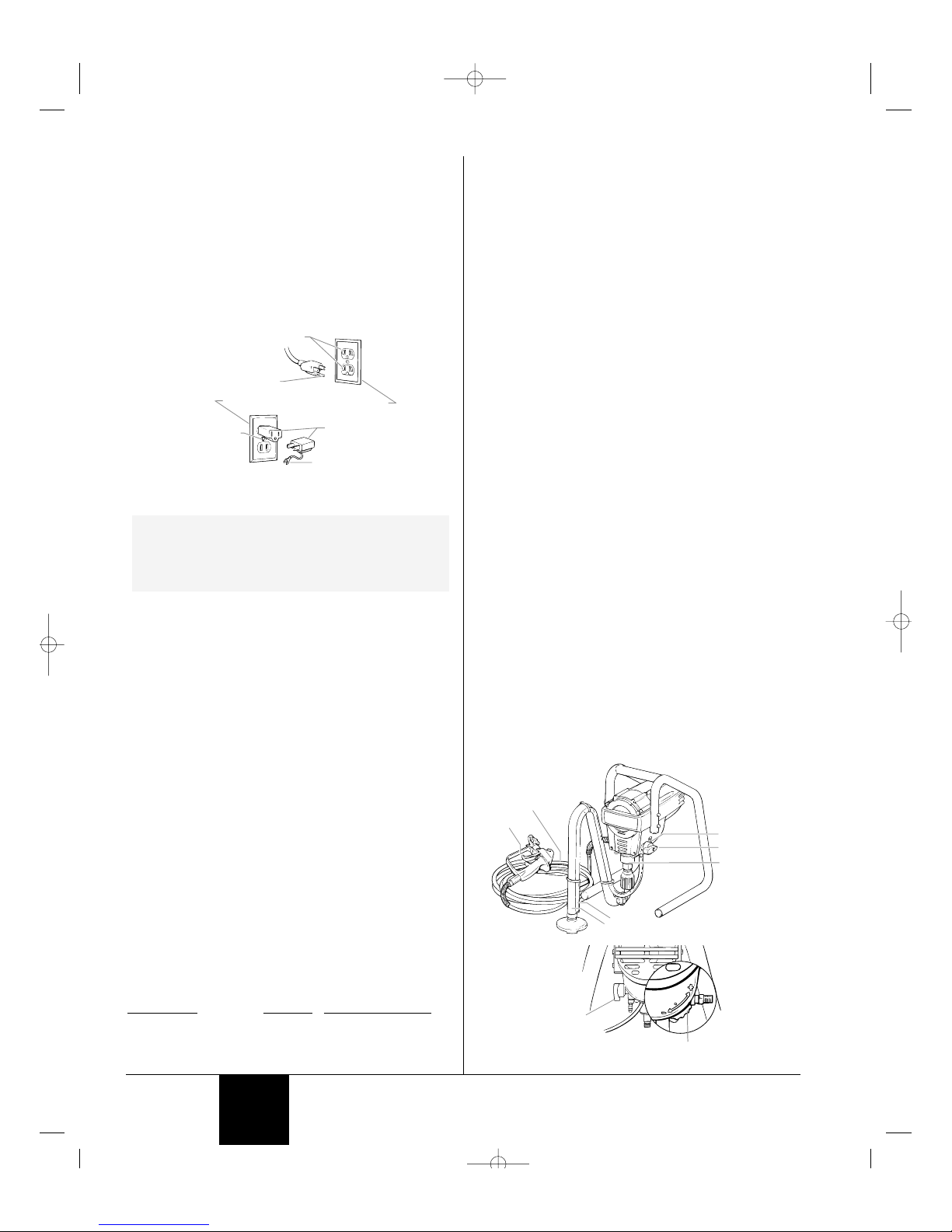
This product is for use on a nominal 120 volt circuit and has a
grounding plug that looks like the plug illustrated below. A
temporary adapter which looks like the adapter illustrated in the
figure below may be used to connect this plug to a 2 pole
receptacle as shown if a properly grounded outlet is not available.
The temporary adapter should be used only until a properly
grounded outlet as shown below can be installed by a qualified
electrician. The green colored rigid ear lug or the grounding
wire extending from the adapter must be connected to a
permanent ground such as a properly grounded outlet box
cover. Whenever the adapter is used, it must be held in place
by a metal screw.
SPECIFICATIONS
Weight ..............................25 lbs. (stand model)
31 lbs. (cart model)
Capacity ...........................Up to .25 gallon (1 liter) per minute.
(K2015 and K20155 Series)
Up to .33 gallon (1.25 liters) per
minute. (K3017 Series)
Up to .42 gallon (1.6 liters) per
minute (K4019 Series)
Power source ...................1/2 Hp universal motor (K20155 and
K2015 Series)
5/8 Hp permanent magnet DC motor
(K3017 Series)
3/4 Hp permanent magnet DC motor
(K4019 Series)
Power requirement...........15 amp minimum circuit on 115
VAC, 60 Hz current.
Generator .........................15 amp A/C.
Spraying pressure ............Up to 2800 psi.
Safety features .................Spray gun trigger lock and pressure
diffuser; built-in tip safety guard;
priming knob for safe pressure
release.
Capability..........................Sprays a variety of paints, oil base
latex, primers, stains, preservatives
and other nonabrasive materials,
including pesticides and liquid
fertilizers.
Unit T
ip Size
: Supplied
Max. Size Supports
K2015, K20155 .013 .015
K3017 .015 .017
K4019 .017 .019
NOTE: This pump is available in two models: a stand
model and a cart model. The stand model is
shown in this manual. All information given for
the stand model applies to the cart model
except where indicated.
Grounded Outlet
Grounding Pin
Tab for
Grounding Screw
Adapter
Metal Screw
Cover for grounded outlet box
4 © 2000 Krebs - All rights reserved.
COMPONENTS
The shipping carton for your painting system contains the
following:
• Suction set and return tube
• Spray gun with filter
• Spray tip assembly
• 25 foot long, 1/4 inch diameter pressure hose (K20155
and K2015)
• 50 foot long, 1/4 inch diameter pressure hose (K3017, K4019)
• Packing lubricant
GENERAL DESCRIPTION
This high performance piston pump is a precision power tool
used for spraying many types of materials. Read and follow
this instruction manual carefully for proper operating
instructions, maintenance and safety information.
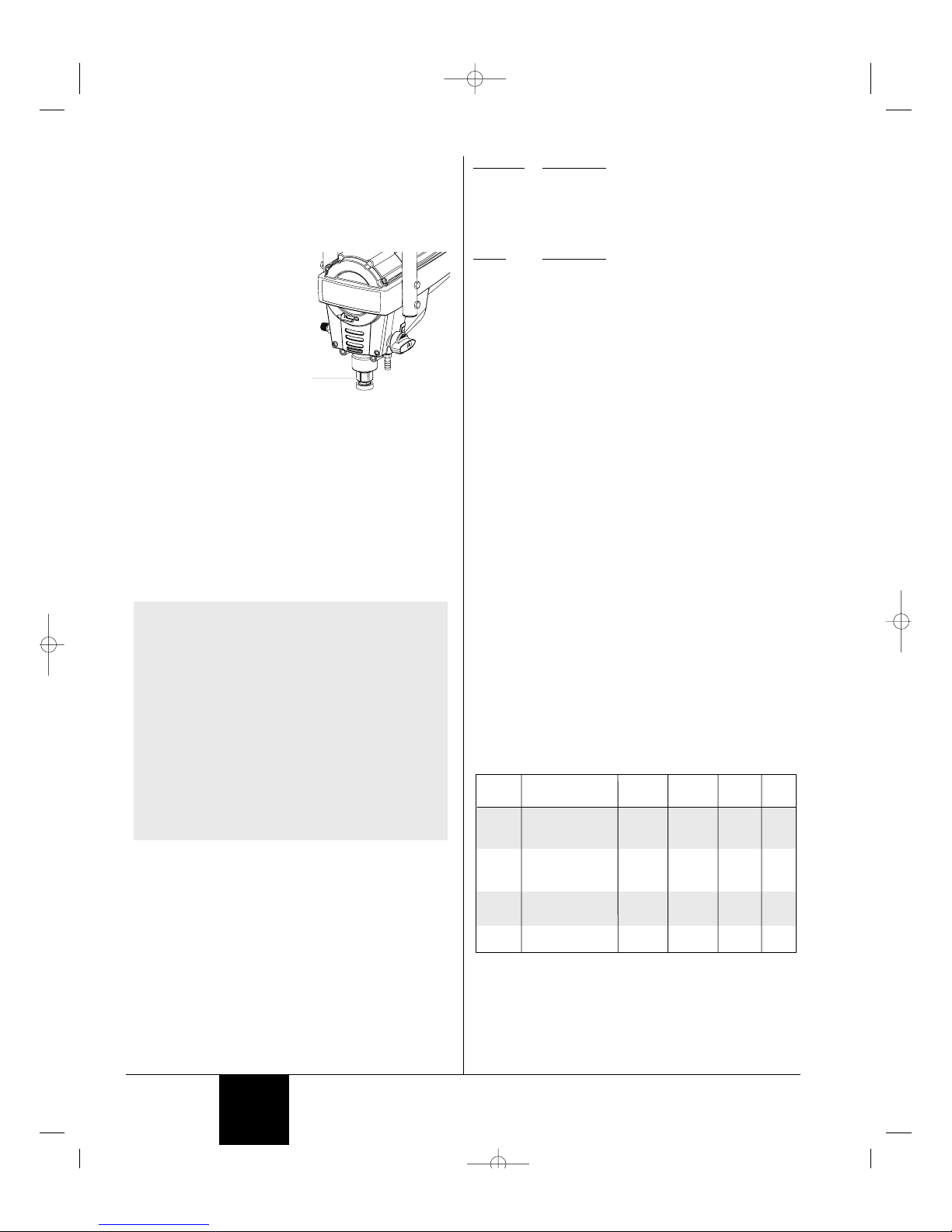
Controls and Functions
ON/OFF Switch ................The ON/OFF switch turns the unit on
and off.
Suction Set.......................Fluid is drawn through the suction
set into the pump.
Fluid Section ....................A piston in the fluid section moves
up and down to create the suction
that draws fluid through the suction
set.
Spray Gun ........................The spray gun controls the delivery
of the fluid being pumped.
Spray Hose ......................The spray hose connects the gun to
the pump.
Return Tube......................Fluid is sent back out through the
return tube to the original container.
PRIME/SPRAY Knob........The PRIME/SPRAY knob directs
fluid to the spray hose when set to
SPRAY or the return tube when set
to PRIME. The arrows on the
PRIME/SPRAY knob shows the
rotation directions for PRIME and
SPRAY.
Pressure Control Dial .......The pressure control dial controls
the amount of force the pump uses
to push the fluid.
PRIME/SPRAY
Knob
PRIME/SPRAY
Knob
Fluid Section
Suction Set
Return Tube
ON/OFF Switch
(Rear View)
Spray Hose
Spray Gun
Pressure Control
Dial
English
0512719A.qrk 21/12/00 1:30 PM Page 4
SETUP
Do not plug in the unit until setup is complete.
Attaching the Handle--Cart Only
1. Position the handle against the cart so that
the holes in the handle line up with the holes
in the cart.
2. Insert the bolts through the holes in the
handle and cart.
3. Tighten the wing nuts onto the bolts.
Attaching the Pail Bracket-Cart Only
1. Position the pail bracket against the
unit so that the holes in the unit line
up with the holes in the bracket.
2. Insert the bolts through the holes in
the bracket and the unit.
3. Tighten the bolts.
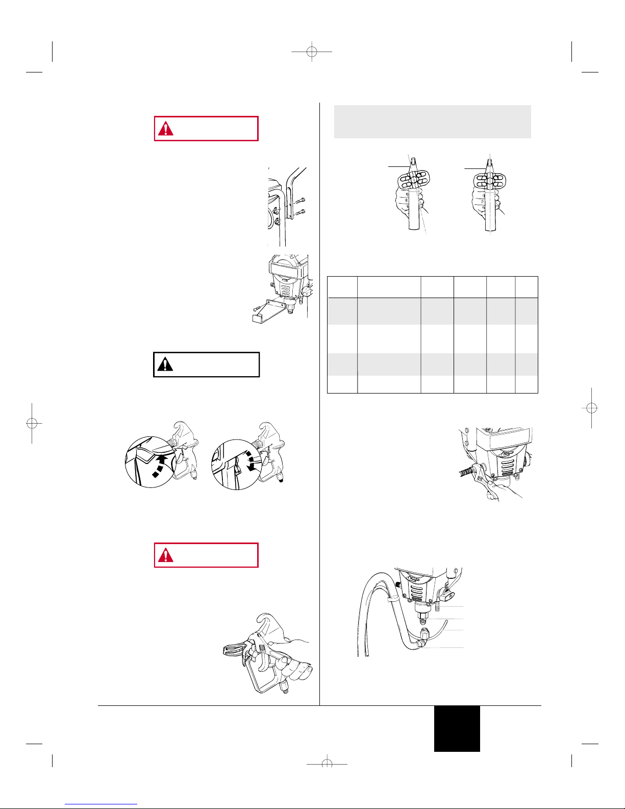
Locking and Unlocking
the Gun
Always lock the trigger off when the gun is not in use.
The gun is secured when the trigger lock is at a 90° angle
(perpendicular) to the trigger in either direction. To unlock the
trigger, turn the trigger lock to be in line with the trigger.
Attaching the Tip to the Gun
POSSIBLE INJECTION HAZARD. Do not spray without the tip
guard in place. Never trigger the gun unless the tip is in
either the spray or the unclog position. Always engage the
gun trigger lock before removing, replacing or cleaning tip.
1. Thread the spray tip onto the
gun. Tighten the nut first
byhand, then tighten more
firmly with a wrench.
WARNING
Gun unocked
(gun will spray)
Gun locked
(gun will not spray)
CAUTION
WARNING
Choosing the Correct Spray Gun Filter
Use the proper gun filter based on the tip size being used.
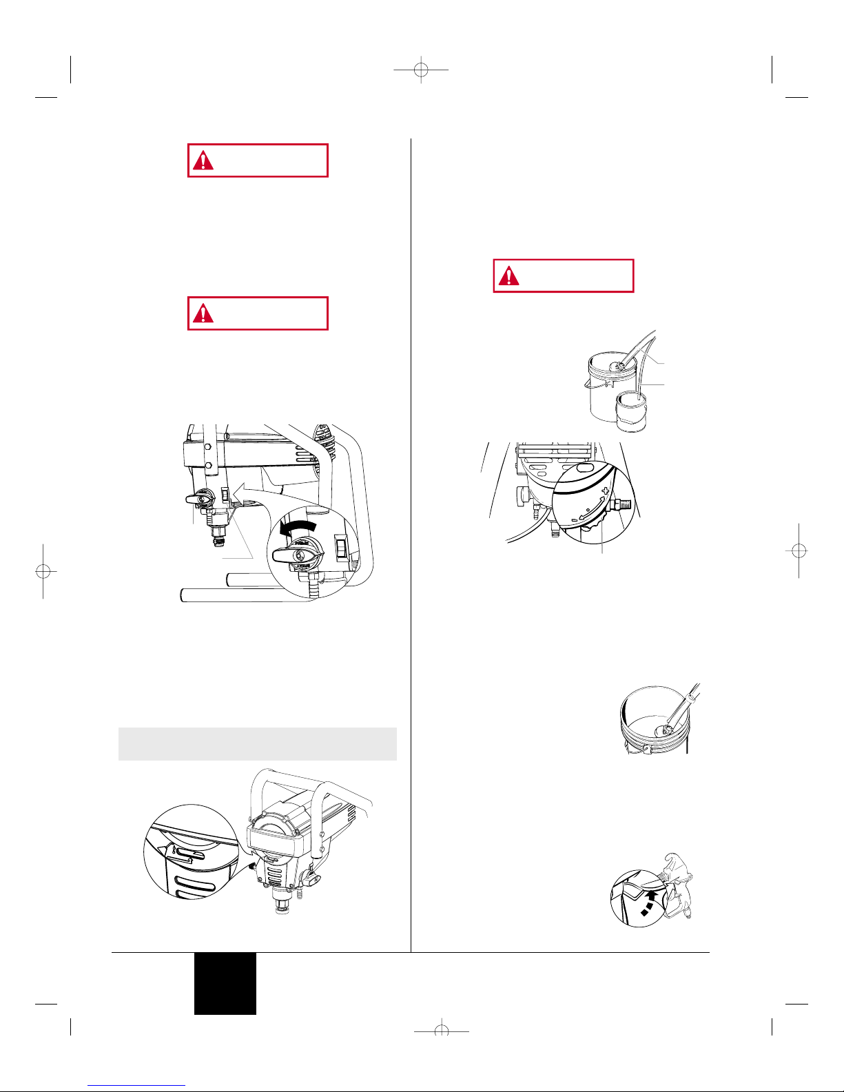
Attaching the Paint Hose
1. Be sure that the motor is turned
to OFF (o).
2. Attach the high pressure hose
to the paint hose port. Use a
wrench to tighten the paint hose
securely.
3. Attach the gun to the other end
of the high pressure hose.
Tighten securely with a wrench.
Attaching the Suction Set and Return Hose
1. Attach the suction tube to the inlet valve and tighten firmly
by hand. Be sure that the threads are straight so that the
fitting turns freely.
2. Press the return tube onto the return tube fitting.
3. Place the suction tube and the return tube into the paint.
4. Place the paint bucket onto the floor or hang on the pail
bracket, depending on the model of pump you have.
Return tube
fitting
Return tube
Inlet valve
Suction set
Part No. Tip Size Filter
Type
Mesh
Number
Qty.Color of
Filter
Body
0154918 .011 Extrafine 180 mesh
0.084 mm
red 2 pack
2 pack
2 pack
2 pack
0154675 .013 - .015 Fine 100 mesh
0.140 mm
yellow
0154842 .017 - .023 Medium 50 mesh
0.315 mm
white
0154919 .023 and up Coarse 30 mesh
0.560 mm
green
Begin
tightening
the tip at
this angle
to achieve
the desired
spray angle
when tight.
NOTE: When attaching tip to the gun, align the tip
guard as shown in figure below, then
tighten with a wrench.
© 2000 Krebs - All rights reserved. 5
English
0512719A.qrk 21/12/00 1:30 PM Page 5
Always lock the gun off when it is not in use.
Plugging in the Unit
1. Check that the ON/OFF switch is in the OFF position (o).
2. Plug the sprayer into a properly grounded outlet or heavy
duty grounded extension cord.
PRESSURE RELIEF PROCEDURE
Be sure to follow the pressure relief procedure when
shutting the unit down for any purpose, including
servicing or adjusting any part of the spray system,
changing or cleaning spray tips, or preparing for cleanup.
1. Lock the spray gun off.
2. Move the ON/OFF switch to the OFF (O) position.
3. Turn the PRIME/SPRAY knob to PRIME.
PRIMING
Preparing to Prime
1. Before priming, squirt some hydraulic oil (P/N 0154908
included with unit) into the indicated area. Light
household oil can be substituted if necessary. This will
prolong seal life of the unit.
NOTE: Apply only a teaspoon amount at a time. Too
much oil may cause the oil to drip into the paint.
o
+
o
+
o
+
+
o
ON/OFF Switch
(+/o)
PRIME/SPRAY
Knob
WARNING
WARNING
6 © 2000 Krebs - All rights reserved.
Purging and Priming
If this unit is new, it is shipped with test fluid in the fluid section
to prevent corrosion during shipment and storage. If you are
going to spray latex paint, this fluid must be purged and
thoroughly cleaned out of the system. If you are going to
spray with solvent-based paint, this fluid must be purged from
the system, but thorough cleaning is not necessary.
If the pump has already been used you will need to purge the
water or solvent used in cleanup and storage.
Always keep the spray gun locked off when purging the pump.
Purging and Priming the Pump for Latex Paint
1. Secure the return tube into a
waste container.
2. Place a full container of paint
underneath the suction tube.
3. Turn the pressure control dial
to minumum pressure (-).
4. Turn the PRIME/SPRAY knob to PRIME.
5. Move the ON/OFF switch to the ON position. If unit does
not start, turn pressure control dial one to two turns until
unit turns on.
6. The unit will begin to draw paint up the suction tube, into
the pump, and out the return tube. Let the unit cycle long
enough to remove test fluid from the pump, or until paint is
coming from the return tube.
7. Remove the return tube from the
waste container and place it in its
operating position above the
container of paint.
8. Keep circulating the paint through the
system until the paint coming out of
the return tube is free of air bubbles.
9. Move the ON/OFF switch to the OFF position.
The pump is now purged. Skip to Purging and Priming the
Spray Hose.
Purging and Priming the Spray Hose
After the pump is purged and primed, you must do the same
for the spray hose.
1. Lock the spray gun off.
2. Remove the spray tip from the gun.
3. Turn the PRIME/SPRAY knob to
SPRAY.
4. Be certain that the spray gun is
unlocked and trigger it into a
waste container. Hold the trigger
Gun locked
(gun will not spray)
Pressure Control
Dial
Return
tube
Suction
tube
WARNING
English
0512719A.qrk 21/12/00 1:30 PM Page 6
until all air, water, or solvent is purged from the spray hose
and paint is flowing freely.
Keep hands clear of the stream of fluid coming from the
spray gun.
Using a metal container, ground the
gun by holding it against the edge of
the container while flushing. Failure to
do so may lead to a static electric
discharge which may cause a fire.
If the PRIME/SPRAY knob is still on SPRAY, there will be
high pressure in the hose and spray gun until the
PRIME/SPRAY knob is turned to PRIME.
5. Turn the PRIME/SPRAY knob to PRIME.
6. Be certain that the spray gun is unlocked and trigger it into
the waste container to be sure that no pressure is left in
the hose.
7. Lock the spray gun off.
8. Attach the spray tip.
SPRAYING
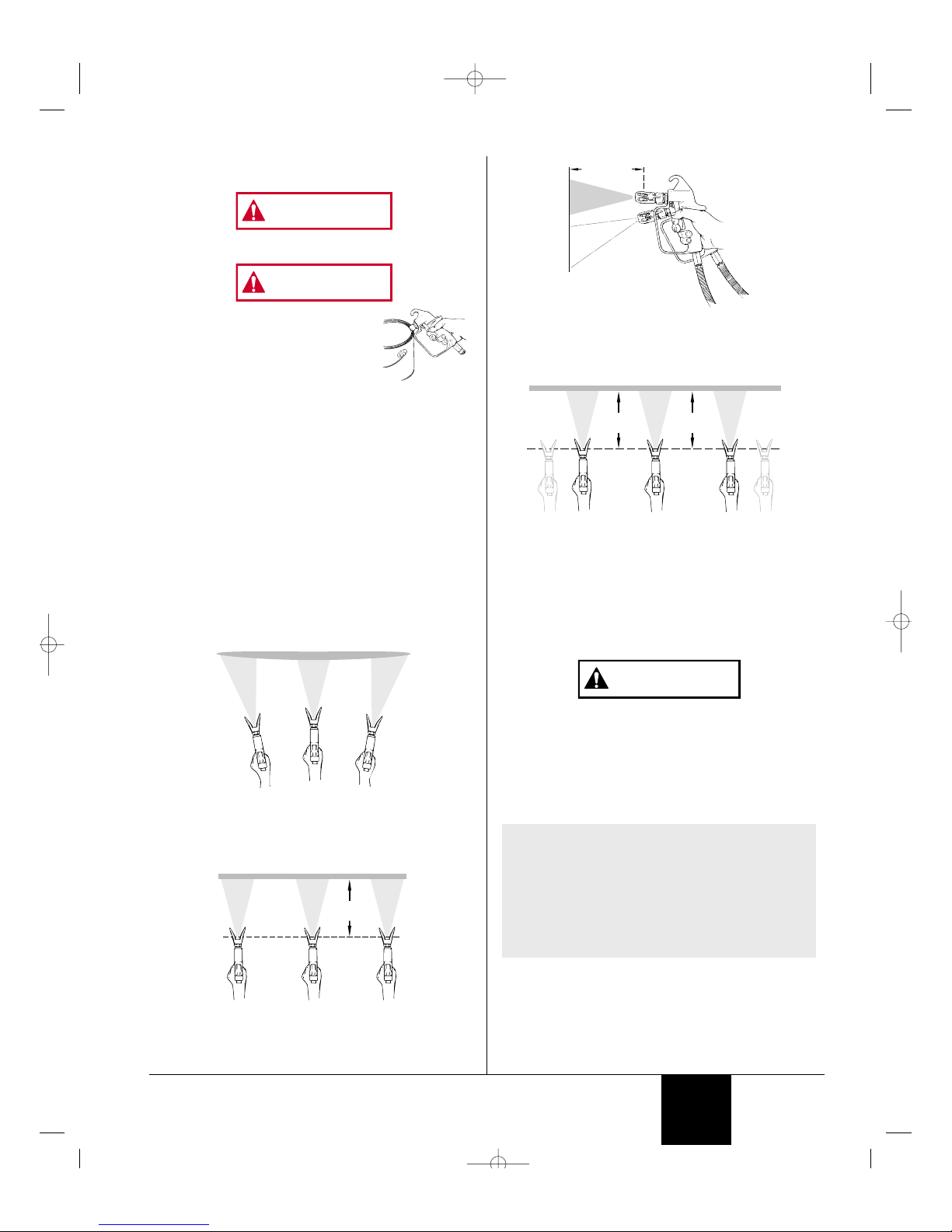
Spraying Technique
The key to a good paint job is an even coating over the entire
surface. This is done by using even strokes. Keep your arm
moving at a constant speed and keep the spray gun at a
constant distance from the surface. The best spraying distance
is 10 to 12 inches between the spray tip and the surface.
Keep the spray gun at right angles to the surface. This means
moving your entire arm back and forth rather than just flexing
your wrist.
Keep the spray gun perpendicular to the surface, otherwise
one end of the pattern will be thicker than the other.
Keep stroke smooth and at an even speed.
Even coat throughout
Approximately
10 to 12 inches
Heavy Coat
Do not flex wrist while spraying.
Light Coat Light Coat
WARNING
WARNING
The spray gun should be triggered by turning it on and off with
each stroke. This will save paint and avoid paint buildup at the
end of the stroke. Do not trigger the gun during the middle of a
stroke. This will result in an uneven spray and splotchy coverage.
Overlap each stroke by about 30%. This will ensure an even coating.
When you stop painting, lock the gun trigger lock, and set the
priming knob to PRIME. Turn the motor switch to OFF and
unplug the sprayer.
If you expect to be gone more than 1 hour, follow the short
term clean up procedure described in the CLEANUP section of
this manual.
Practice
Be sure that the paint hose is free of kinks and clear of
objects with sharp cutting edges.
1. Turn the PRIME/SPRAY knob to SPRAY.
2. Turn the pressure contol dial to its highest setting (+).
The spray hose should stiffen as paint begins to flow
through it.
3. When paint reaches the spray tip, spray a test area to
check the spray pattern.
NOTE: The pressure control dial should be set at the
maximum setting (+) in most cases when
using thicker viscosity materials such as latex
paints. You may have to lower the pressure
setting (-) when using thinner viscosity
materials such as stains. If the pressure is
set too high, you will over atomize and waste
paint. If the pressure is set too low, tailing
will appear or the paint will spatter out in
gobs rather than a fine spray.
CAUTION
Proper way to trigger the spray gun
Approximately
10 to 12 inches
Keep stroke
even
Start stroke End strokePull trigger Release triggerKeep steady
Approximately
10 to 12 inches
Wrong way
Right way
© 2000 Krebs - All rights reserved. 7
English
0512719A.qrk 21/12/00 1:30 PM Page 7
CLEAN UP
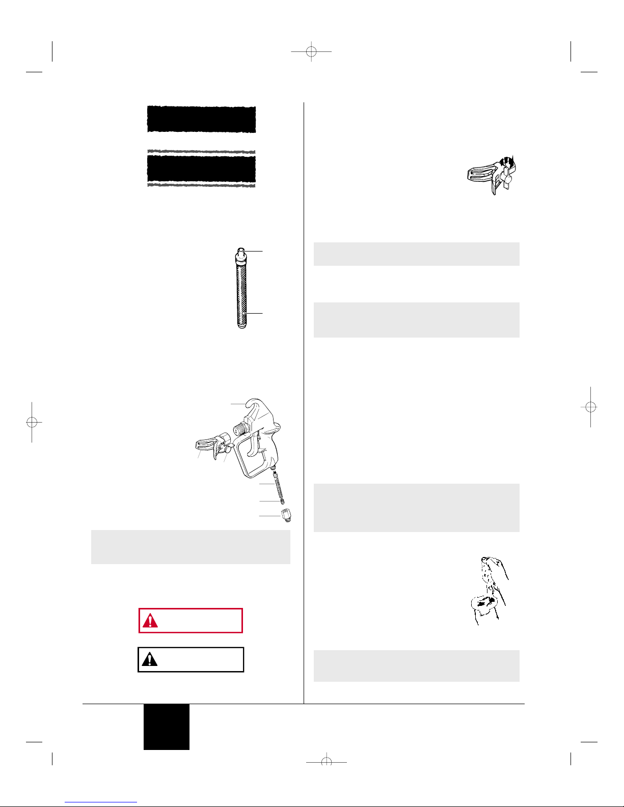
Cleaning the Spray Gun Filter
The spray gun includes a filter to catch
dirt particles before they reach the spray
tip. If this filter becomes clogged or
obstructed it will reduce the flow of
paint, changing the spray pattern and
possibly damaging the filter.
Clean the filter with a brush. Never
poke the filter with a sharp instrument.
This filter must be cleaned daily. If the
material being used is old or contains
hardened particles, then the filter should be cleaned
approximately every 4 hours.
If the filter is not cleaned at the proper time, it will plug from
the top down. When there is about 1 inch of filter that isn't
plugged, the heavy flow of paint will blow pin holes in the filter.
Holes in the filter will allow unwanted particles to get into the
spray tip, causing the spray tip to clog.
Changing the
Filter
1. Unscrew fitting #6 from
the gun, making sure not
to lose the spring #5.
Remove the old filter.
2. Slide the new filter,
tapered end first, into the
gun housing.
3. Replace the spring #5 and the fitting #6. Tighten with a
wrench.
Unclogging the Spray Tip
Do not attempt to unclog or clean the tip with your finger.
Do not use a needle or other sharp pointed instrument to
clean the tip. The hard tungsten carbide is brittle and can
be chipped.
CAUTION
WARNING
NOTE: The tapered end of the filter must be loaded
properly into the gun. Improper assembly
will result in a plugged tip.
4
1
3
2
5
6
Pin hole
Filter top
Good spray pattern
Paint tailing pattern
8 © 2000 Krebs - All rights reserved.
The spray gun is equipped with a reversible tip which allows
you to blow out any particles of old paint or other contaminants
that may obstruct the paint flow through the tip. If the spray
pattern becomes distorted or stops completely while the gun is
triggered, follow these steps:
1. Release the trigger and lock the gun off.
2. Rotate the reversible tip cylinder arrow
180° so that the point of the arrow is
toward the rear of the gun.
3. Unlock the gun and squeeze the trigger,
pointing the gun at a scrap piece of
wood or cardboard. This allows pressure in the spray
hose to blow out the obstruction. When the nozzle is
clean, paint will come out in a straight, high pressure
stream.
4. Release the trigger and lock the gun off.
5. Reverse the tip so the arrow points forward again.
6. Unlock the gun and resume spraying.
Cleaning the Spray Tip
1. Turn the PRIME/SPRAY knob to PRIME. This will bleed
off the pressure in the spray hose and filter. Trigger the
gun to be sure that the pressure is gone. Refer to the
PRESSURE RELIEF PROCEDURE section.
2. Lock the spray gun off.
3. Remove the spray tip assembly from the gun with a
wrench.
4. Turn the spray tip so that the arrow tab is perpendicular to
the spray guard and pull the tip out.
5. Push the seal and washer out the back end of the tip
guard.
6. Wash all the tip assembly parts with soapy water or an
appropriate solvent.
Cleaning the Suction Set Screen
The screen at the bottom of the suction
set may also need cleaning. Check it
every time you change paint buckets.
Remove the screen by pulling it out of the
retainer with a plier. Clean the screen with
water or solvent and a soft-bristle brush.
Short Term Storage (up to
16 hours)
NOTE: Follow these steps when using latex paints
only. If using materials that are oil-based,
follow the long-term storage steps.
NOTE: If spraying with latex paint, use warm soapy
water for cleaning. If using oil or alkyd-based
paints, use mineral spirits of paint thinner.
Refer to the paint manufacturer’s instructions
for specific recommendations.
NOTE: It is sometimes necessary to relieve pump
pressure by turning the PRIME/SPRAY knob to
PRIME before rotating the reversible tip.
NOTE: If the spray tip remains clogged, follow the
Cleaning the Spray Tip procedure.
English
0512719A.qrk 21/12/00 1:30 PM Page 8

Shutdown
1. Lock the spray gun off.
2. Turn the PRIME/SPRAY knob to PRIME.
3. Turn the motor switch to OFF (O) and unplug the sprayer.
4. For latex materials only, pour 1/2 cup water slowly on the
top of the paint to prevent the paint from drying.
5. Wrap the spray gun assembly in a damp cloth and place it
in a plastic bag. Seal the bag shut.
6. Place the sprayer in a safe place out of the sun for shortterm storage.
Startup
1. Remove the gun from the plastic bag.
2. Stir the water into the paint for latex materials. Remove
the seal from the paint bucket and stir the paint for all
other materials.
3. Check to be sure that the PRIME/SPRAY knob is set to
PRIME.
4. Plug sprayer in and turn the motor switch to ON.
5. Turn the PRIME/SPRAY knob to SPRAY.
6. Test the sprayer on a practice piece and begin spraying.
Long-term Storage (16 + hours)
Special clean up instructions for use with flammable
solvents:
IMPORTANT
• ALWAYS FLUSH SPRAY GUN AT LEAST ONE (1)
HOSE LENGTH AWAY FROM SPRAY PUMP.
• If collecting flushed solvents in one (1) gallon metal
container, place it into an empty five (5) gallon metal
container, then flush.
• Area must be free of vapors.
• Follow all cleanup instructions.
Cleaning the Suction Tube
1. Lock the spray gun off.
2. Turn the PRIME/SPRAY knob to PRIME
3. Turn the motor switch to OFF and unplug the sprayer.
4. Remove the suction tube from the paint and hold it above a
bucket of water or solvent. Leave the return tube in the paint
bucket.
Do not use mineral spirits or paint thinner on latex paint,
or the mixture will turn into a jelly-like substance which is
difficult to remove.
5. Plug the sprayer in and turn the motor switch to ON.
6. Trigger the gun to relieve pressure and lock the gun.
7. Remove the spray tip assembly and place it into a
container of water or appropriate solvent for the type of
CAUTION
NOTE: If spraying with latex paint, use warm soapy
water for cleaning. If using oil or alkyd-based
paints, use mineral spirits or paint thinner.
WARNING
material with which you are spraying.
8. Place the attached suction tube and return tube into a
container of water or appropriate solvent for the type of
material with which you are spraying.
9. Let the water or solvent circulate for 2-3 minutes to flush
paint out of the pump, the suction tube and the return tube.
Cleaning the Paint Hose
1. To save paint left in the hose,
release the gun trigger lock, place
the gun body with the spray tip
removed against the paint
container, and carefully trigger the
gun into the container.
2. Turn the PRIME/SPRAY knob to
SPRAY.
3. As soon as the water or solvent starts to come into the
bucket, release the trigger.
4. Change to clean water or solvent and continue circulating
for another 5 minutes to thoroughly clean the hose, pump
and spray gun.
5. Turn the PRIME/SPRAY knob to PRIME.
6. Trigger the gun to remove any pressure which may still be
in the hose.
7. Lock the spray gun off.
8. Turn the motor switch to OFF.
9. Cover the paint container and set it aside.
Cleaning the Gun
1. Remove the spray gun from paint hose using a wrench.
2. Remove the filter housing from the gun. Place the gun
and the filter assembly into a container of water or solvent
to soak.
3. Clean the spray tip and gun filter with a soft brush.
Assemble the spray tip in the cleaning position with the
arrow pointing to the back of the gun.
4. Attach the paint hose to the gun and tighten using a
wrench.
5. Turn the motor switch to ON.
6. Unlock the gun.
7. Turn the PRIME/SPRAY knob to SPRAY and point the gun
to the side of the cleaning bucket.
8. Continue to trigger the gun for
approximately 30 seconds.
9. Turn the PRIME/SPRAY knob to
PRIME.
10. Trigger the gun to remove any
pressure which may still be in
the hose.
11. Lock the spray gun off.
12. Turn the motor switch to OFF.
Preparing the Sprayer for Long-term Storage
1. Remove the tip assembly and raise the suction set above
the cleaning solution.
2. Turn the motor to ON.
© 2000 Krebs - All rights reserved. 9
English
0512719A.qrk 21/12/00 1:30 PM Page 9
3. Turn the PRIME/SPRAY knob to SPRAY.
4. Remove the large suction tube from the inlet valve and
point the gun into the cleaning bucket.
5. Unlock the gun and trigger it into the cleaning bucket until
the hose is pumped dry.
6. Turn the PRIME/SPRAY knob to PRIME.
7. Clean the threads of
the inlet valve with a
damp cloth.
8. Fill the inlet valve with a
light household oil.
Slowly increase the
pressure to distribute
the oil through the
pump. Also add oil to
top bushing of unit in
order to prolong seal
life.
9. Turn the PRIME/SPRAY knob to SPRAY to distribute the oil.
10. Replace the large suction tube onto the inlet valve.
11. Turn the PRIME/SPRAY knob to PRIME.
12. Trigger the gun to remove any pressure which may still be
in the hose.
13. Lock the spray gun off.
14. Turn the motor switch to OFF.
15. Remove and clean the suction set filter in clean water or
the appropriate solvent. Use a soft brush. Return the
suction set filter to its original position.
16. Wipe the entire unit, hose and gun with a damp cloth to
remove accumulated paint.
MAINTENANCE
Daily Maintenance
The only daily maintenance necessary is thorough cleaning.
Follow the cleaning procedures in this manual.
Extended Maintenance
Some pump parts eventually wear out from use and must be
replaced. The following list indicates the available repair kits
for the parts replaced by each kit. However, pump
performance is the only reliable indicator of when to replace
wear parts. Refer to the Troubleshooting section for more
information on when to use these kits.
NOTE: Thorough cleaning and lubrication of the
sprayer is the most important step you can
take to ensure proper operation after storage.
NOTE: If you spray oil-or solvent-based material, the
following cleaning steps must be followed in
addition to the steps in the owner’s manual to
properly clean and lubricate the pump before
storage.
1. Flush the pump with the appropriate solvent as
recommended on the paint manufacturer’s label.
Follow the steps in the owner’s manual.
2. After flushing with solvent, run warm, soapy water
through the pump to remove the solvent material. The
solvent must be removed to allow proper lubrication of
the pump prior to storage.
3. Lubricate the pump using a light household oil as
described in the owner’s manual.
Inlet
valve
10 © 2000 Krebs - All rights reserved.
Kit Part # Description
0512228 Fluid Section Seal Kit (K2015, K20155)
0512222 Valve Replacement Kit (K2015, K20155)
0512229 Fluid Section Seal Kit (K3017, K4019 Series)
0512224 Valve Replacement Kit (K3017, K4019 Series)
ACCESSORIES
Part # Description
0154908 Separating Oil
0154830 Hose, Whip End, 5’ x 3/16”
0270192 Hose, Wireless, 25’ x 1/4"
0270118 Hose, Wireless, 50’ x 1/4"
0093896 Hose Connector, 1/4” x 1/4”M
0088154 Pressure Gauge
0512130 Tip Extension, 12”
0512131 Tip Extension, 24”
0152001 Power Roller Gun Attachment
0155206 9" Roller Cover, 3/8” Nap
0152307 9" Roller Cover, 1/2” Nap
0155208 9" Roller Cover, 3/4” Nap
0152310 9" Roller Cover, 1-1/4” Nap
0501002 GX-08 Four Finger Metal Airless Spray Gun
0501004 GX-07 Two Finger Metal Airless Spray Gun
0501026 GX-06 Two Finger Plastic Airless Spray Gun
0501029 GX-10 Two Finger Metal Airless Spray Gun w/Swivel
0501010 Guard Assembly, F-Thread
0501011 Guard Assembly, G-Thread
0512132 3 Foot Pole Extension w/Swivel
0512133 6 Foot Pole Extension w/Swivel
0154839 All Guard Pump Protector
0512134 180 Degree Swivel
0512135 F- to G-Thread Adapter
0154832 Suction Tube Filter (2 Pack)
0501411 411 Trade Spray Tip
0501413 413 Trade Spray Tip
0501415 415 Trade Spray Tip
0501417 417 Trade Spray Tip
0501419 419 Trade Spray Tip
0501515 515 Trade Spray Tip
0501517 517 Trade Spray Tip
0501519 519 Trade Spray Tip
0093930 Anti-Seize Compound
0156113 TR-10 Telescoping Roller, 9", 3/8" Nap
Choosing the Correct Spray Gun Filter
Use the proper gun filter based on the type of material being
applied as shown below.
Part No. Tip Size Filter
Type
Mesh
Number
Qty.Color of
Filter
Body
0154918 .011 Extrafine 180 mesh
0.084 mm
red 2 pack
2 pack
2 pack
2 pack
0154675 .013 - .015 Fine 100 mesh
0.140 mm
yellow
0154842 .017 - .023 Medium 50 mesh
0.315 mm
white
0154919 .023 and up Coarse 30 mesh
0.560 mm
green
English
0512719A.qrk 21/12/00 1:30 PM Page 10
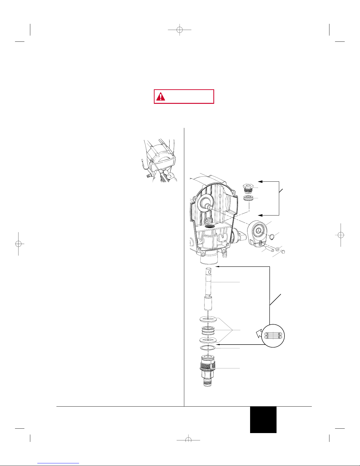
Disassembly of the Fluid Section
1. Remove the suction set.
2. Remove the front cover and the four
screws that secure it using a T20
Torx head driver.
3. Remove the yoke screw and washer
that secures the dowel pin. The
dowel pin connects the yoke to the
piston.
4. Using the pliers, pull the dowel pin out.
5a. For models K2015 and K20155 rotate the pump shaft so
the piston is in the top dead center position. This can be
done by pushing on the yoke. This is required to
disassemble all the parts.
5b. For models K3017 and K4019, Inspect the yoke assembly
and piston, In order to remove all the necessary parts, the
piston must not be in the bottom dead center position. If
the piston is at the bottom of the stroke, install the front
cover and screws, turn the pump on briefly to index the
piston, unplug the unit, and repeat step 2.
6. Unscrew and remove the inlet valve assembly using an
adjustable wrench.
7. Remove the piston assembly by pushing down on the
piston near the yoke.
8. Uscrew and remove the top nut using and adjustable wrench.
9. Remove the worn seals using a flat head screwdriver or
punch. Remove the top seal from the top and the bottom
seal from the bottom by pressing against the side of the
seal and popping it out. Be sure not to scratch the
housing where the seals are located.
10. Clean the area where the new seals are to be installed.
Assembly of the Fluid Section
1. Lubricate the new top seal with Amspray Separating Oil
(P/N 0154908) or light household oil and by hand place the
seal (cup side of seal down) into the top port of the housing.
2. Place the top nut into the top of the housing and tighten
with an adjustable wrench. This will drive the top seal into
the correct position.
3. Turn the pump upside down. Place the two (2) large Orings over the new plastic bottom seal, lubricate similar to
the top seal, and place the bottom seal with O-rings into
the bottom (inlet) of housing by hand. Insert the inlet valve
and thread into position to properly seat the seal.
Remove inlet and go to step four (4).
4. Push the new piston into the bottom (inlet) of the housing
and align with the yoke. A ruber mallet may be used. Be
careful not to damage the piston.
5. Install the dowel pin to connect the yoke to the piston.
The piston may have to be moved up or down to do this.
6. Install the yoke screw and washer to secure the dowel pin.
7. Install the new O-ring on the inlet assembly, lubricate,
thread into the bottom (inlet) of the housing, and tighten
with an adjustable wrench. This will drive the bottom seal
into the correct position.
8. Turn pump right side up and apply a few drops of
Amspray Separating Oil or light household oil between the
top nut and piston. This will prolong the seal life.
9. Install front cover and four (4) screws.
10. Install the suction set.
Dowel
Screw
0512228
(K2015,
K20155 Kit)
0512229
(K3017 and
K4019 Kit)
0512228
(K2015,
K20155 Kit)
0512229
(K3017 and
K4019 Kit)
Washer
Retaining
Ring
Yoke
Piston
Assembly
Top Seal
(cup down)
Top Nut
Bottom
Seal
O-ring
Inlet Valve
Assembly
Bottom Seal
(Cross-Section)
© 2000 Krebs - All rights reserved. 11
English
FLUID SECTION SEAL REPLACEMENT INSTRUCTIONS
KIT 0512228 (Models K2015, K20155)
KIT 0512229 (Models K3017, K4019)
Always wear protective eye wear while servicing the pump. Be sure to follow the PRESSURE RELIEF PROCEDURE when
shutting the unit down for any purpose, including servicing or adjusting. After performing the pressure relief procedure, be
sure to unplug the unit before servicing or adjusting.
Area must be free of solvents and paint fumes.
WARNING
0512719A.qrk 21/12/00 1:30 PM Page 11
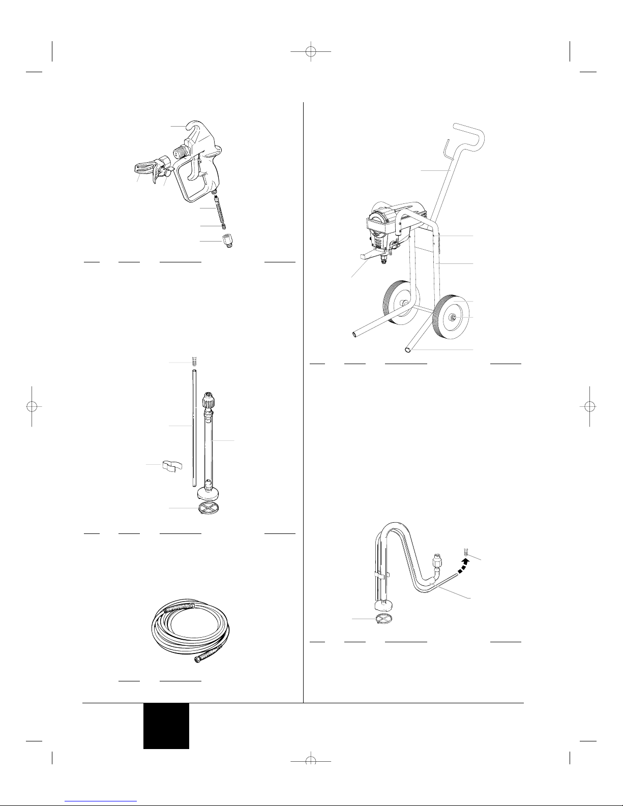
PARTS LIST
Spray Gun
Item Part # Description Quantity
1 0512120 Plastic gun assembly............................1
0512121 Metal gun assembly..............................1
2 0501011 Guard assembly....................................1
3 0501413 Tip* ........................................................1
4 0154675 Filter assembly, 100 mesh ....................1
5 0043590 Spring, filter...........................................1
6 0278357 Cap, filter housing.................................1
*See Accessories section
Suction Set (K2015, K3017, K4019)
Item Part # Description Quantity
1 0512220 Suction set assembly............................1
2 0512389 Return tube...........................................1
3 9885553 Return tube fitting ....................................1
4 0154832 Filter......................................................1
5 0512390 Clip........................................................3
Paint Hose
Part # Description
0291002 1/4” x 25’ Hose (K2015, K20155)
0291000 1/4” x 50’ Hose (K3017 and K4019)
1
2
3
4
5
4
1
3
2
5
6
12 © 2000 Krebs - All rights reserved.
Cart Assembly (K3017, K4019)
Item Part # Description Quantity
1 0512406 Handle . . . . . . . . . . . . . . . . . . . . . . . . 1
2 9800108 Bolt . . . . . . . . . . . . . . . . . . . . . . . . . . 4
9821503 Washer . . . . . . . . . . . . . . . . . . . . . . . 4
9810111 Nut. . . . . . . . . . . . . . . . . . . . . . . . . . . 4
3 0512336 Stand (K20155) . . . . . . . . . . . . . . . . . 1
0512383 Cart (K2015) . . . . . . . . . . . . . . . . . . . 1
0512368 Cart (K3017) . . . . . . . . . . . . . . . . . . . 1
0512385 Cart (K4019) . . . . . . . . . . . . . . . . . . . 1
4 0512396 Wheel (K2015) . . . . . . . . . . . . . . . . . . 2
0512397 Wheel (K3017). . . . . . . . . . . . . . . . . . 2
0278373 Wheel (K4019). . . . . . . . . . . . . . . . . . 2
5 0275728 Cap (K2015, K3017) . . . . . . . . . . . . . 2
9890104 Cap (K4019) . . . . . . . . . . . . . . . . . . . 2
6 9885546 Plug . . . . . . . . . . . . . . . . . . . . . . . . . . 4
7 0512355 Pail Bracket . . . . . . . . . . . . . . . . . . . . 1
Suction Set (K20155)
Item Part # Description Quantity
1 0512215 Suction set assembly............................1
2 9885553 Return tube fitting ....................................1
3 0154832 Filter......................................................1
1
2
3
1
2
3
4
5
6
7
English
0512719B.qxd 4/6/01 9:56 AM Page 12
© 2000 Krebs - All rights reserved. 13
English
Problem
A. The sprayer does not start.
B. The sprayer starts but does
not draw in paint when the
PRIME/SPRAY knob is set to
PRIME.
C. The sprayer draws up paint
but the pressure drops when
the gun is triggered.
D. The PRIME/SPRAY valve is
on SPRAY and there is flow
through the return tube.
E. The spray gun leaks.
F. The tip assembly leaks.
G. The spray gun will not spray.
H. The paint pattern is tailing.
Cause
1. The sprayer is not plugged in.
2. The ON/OFF switch is set to OFF.
3. A fuse is blown in the sprayer.
4. No voltage is coming from the wall plug.
5. The sprayer was turned off while still under
pressure.
6. The extension cord is damaged or has too
low a capacity.
7. There is a problem with the motor.
1. The unit will not prime properly or has lost prime.
2. The paint bucket is empty or the suction
tube is not totally immersed in the paint.
3. The suction set is clogged.
4. The suction tube is loose at the inlet valve.
5. The inlet or outlet valve is stuck.
6. The PRIME/SPRAY valve is plugged.
7. The inlet valve is worn or damaged.
1. The spray tip is worn.
2. The suction set screen is clogged.
3. The gun or spray tip filter is plugged.
4. The paint is too heavy or coarse.
5. The outlet valve assembly is dirty or worn.
6. The inlet valve assembly is damaged or worn.
1. The PRIME/SPRAY valve is dirty or worn.
1. Internal parts of the gun are worn
or dirty.
1. The tip was assembled incorrectly.
2. A seal is worn.
1. The spray tip, the gun filter or the tip filter is
plugged.
2. The spray tip is in the CLEAN position.
1. The pressure is set too low.
2. The gun, the tip, or the suction filter
is plugged.
3. The suction tube is loose at the inlet valve.
4. The tip is worn.
5. The paint is too thick.
6. Pressure loss.
Solution
1. Plug the sprayer in.
2. Turn the ON/OFF switch to ON.
3. Take sprayer to Wagner Authorized Service Center
4. Properly test the power supply voltage.
5. Turn pressure control knob to maximum setting (+).
6. Replace the extension cord.
7. Take the sprayer to a Wagner Authorized Service Center.
1. Try to prime the unit again.
2. Refill the bucket or immerse the suction tube in
paint.
3. Clean the suction set.
4. Clean the tube connection and tighten it securely.
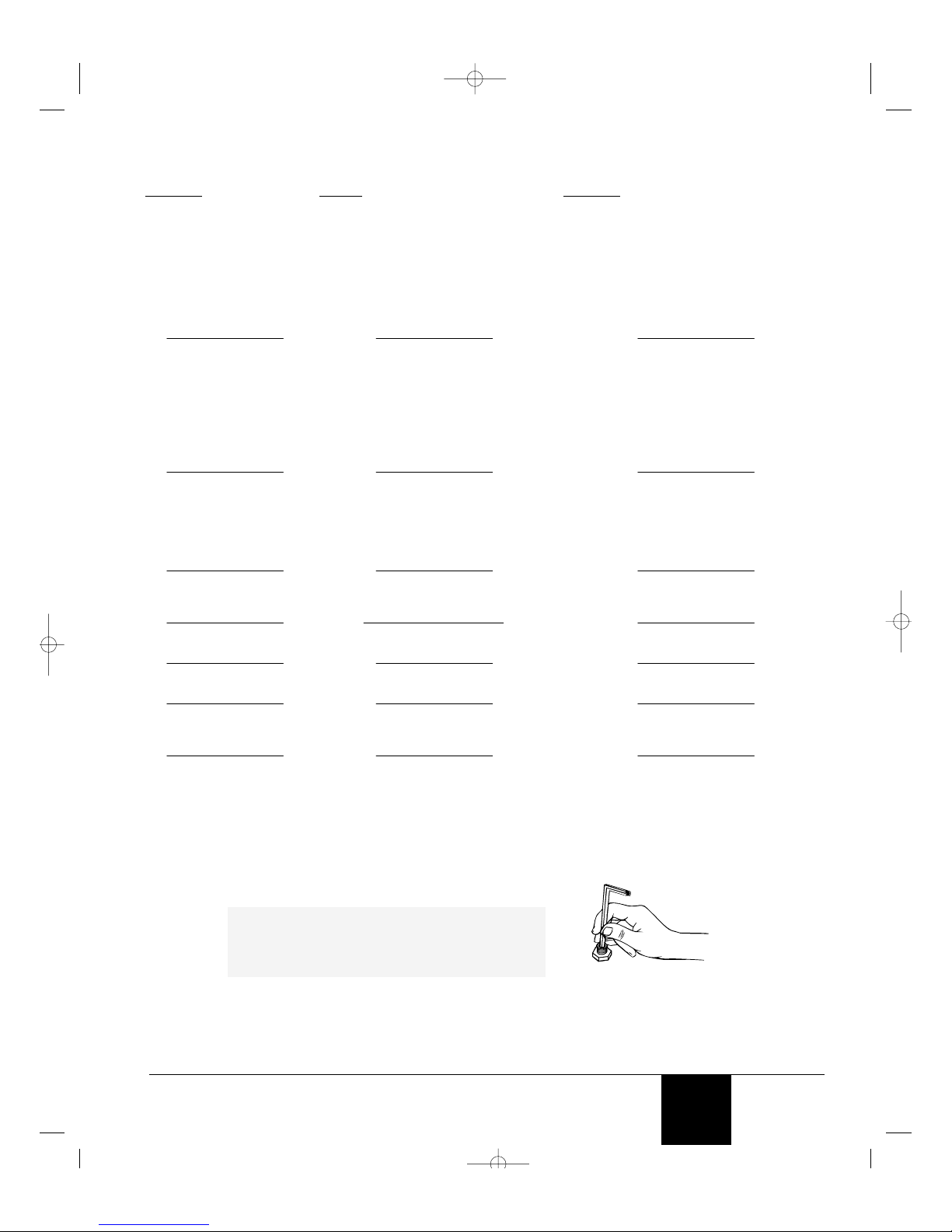
5. Clean the inlet and outlet valves and replace any
worn parts.* Inlet may be stuck from old paint.
Insert allen wrench to release (see figure below).
6. Take sprayer to Wagner Authorized Service Center.
7. Replace the inlet valve.*
1. Replace the spray tip with a new tip.**
2. Clean the suction set screen.
3. Clean or replace the proper filter. Always keep
extra filters on hand.
4. Thin or strain the paint.
5. Clean or replace the outlet valve assembly.*
6. Replace the inlet valve.*
1. Take sprayer to Wagner Authorized Service Center.
1. Take the sprayer to a Wagner Authorized Service
Center.
1. Check the tip assembly and assemble properly.
2. Replace the seal.*
1. Clean the spray tip, gun filter or tip filter.
2. Put the tip in the SPRAY position.
1. Increase the pressure.
2. Clean the filters.
3. Tighten the suction tube fitting.
4. Replace the spray tip.
5. Thin the paint.
6. Refer to Causes and Solutions for problem B.
TROUBLESHOOTING
* Special repair kits with instructions are available for these procedures. Refer to the Maintenance section of this manual for a list
of the kits and their part numbers.
** Additional parts are available for this procedure. Refer to the Accessories section of this manual for a list of the parts and their
part numbers.
NOTE: The electric motor should always be kept clean
and dry. Paint acts as an insulator. Too much
paint on the motor will cause the motor to
overheat.
0512719A.qrk 21/12/00 1:30 PM Page 13
TABLE DES MATIÈRES
SÉCURITE . . . . . . . . . . . . . . . . . . . . . . . . . . . . . . . . . . . . . 14
SPECIFICATION . . . . . . . . . . . . . . . . . . . . . . . . . . . . . . . . 16
COMPOSANTS . . . . . . . . . . . . . . . . . . . . . . . . . . . . . . . . . 16
DESCRIPTION GÉNÉRALE . . . . . . . . . . . . . . . . . . . . . . . . 16
Commandes et fonctions . . . . . . . . . . . . . . . . . . . . . . . 16
MONTAGE . . . . . . . . . . . . . . . . . . . . . . . . . . . . . . . . . . . . . 17
Fixation de la poignée-Modèle sur chariot seulement . . 17
Fixation de la patte de fixation du seau-Modèle sur chariot .
seulement. . . . . . . . . . . . . . . . . . . . . . . . . . . . . . . . . . . . . 17
Verrouillage et déverouillage du pistolet . . . . . . . . . . . . 17
Comment attacher la tête . . . . . . . . . . . . . . . . . . . . . . . 17
Fixation du tuyau de pulvérisation . . . . . . . . . . . . . . . . 18
Fixation de l’ensemble d’aspiration et du tube de retour 18
Branchement de l’appereil . . . . . . . . . . . . . . . . . . . . . . 18
LIMITATION DE LA PRESSION PROCÉDURE. . . . . . . . . . 18
AMORÇAGE . . . . . . . . . . . . . . . . . . . . . . . . . . . . . . . . . . . 18
Purge et amorçage . . . . . . . . . . . . . . . . . . . . . . . . . . . 18
PULVÉRISATION . . . . . . . . . . . . . . . . . . . . . . . . . . . . . . . . 19
Technique de pulvérisation . . . . . . . . . . . . . . . . . . . . . . 19
Practique . . . . . . . . . . . . . . . . . . . . . . . . . . . . . . . . . . . 20
NETTOYAGE D’ENTRETIEN . . . . . . . . . . . . . . . . . . . . . . . 20
Nettoyage du filtre du pistolet . . . . . . . . . . . . . . . . . . . . 20
Débouchage de la tête du pulvérisateur . . . . . . . . . . . . 20
Nettoyage de la tête du pulvérisateur . . . . . . . . . . . . . . 21
Nettoyage de l’écran de l’ensemble d’aspiration . . . . . . 21
NETTOYAGE APRÈS PULVÉRISATION ET ENTREPOSAGE. 21
Entresposage à court terme / de nuit . . . . . . . . . . . . . . 21
Rangement à long terme . . . . . . . . . . . . . . . . . . . . . . . 21
MAINTENANCE . . . . . . . . . . . . . . . . . . . . . . . . . . . . . . . . . 23
Entretien quotidien . . . . . . . . . . . . . . . . . . . . . . . . . . . . 23
Entretien prolongé . . . . . . . . . . . . . . . . . . . . . . . . . . . . 23
ACCESSOIRES . . . . . . . . . . . . . . . . . . . . . . . . . . . . . . . . . 23
COMPARTIMENT LIQUIDE . . . . . . . . . . . . . . . . . . . . . . . . 25
LISTE DE PIÉCES . . . . . . . . . . . . . . . . . . . . . . . . . . . . . . . 26
EN CAS DE PROLEME . . . . . . . . . . . . . . . . . . . . . . . . . . . 27
GARANTIE LIMITÉE . . . . . . . . . . . . . . . . . . . . . . . . . . . . . 42
MESURES DE SECURITÉ
Le présent manuel comprend des renseignements devant être
lus attentivement avant toute utilisation de l'appareil. Lorsque
l'un des symboles suivants apparaît, il est recommandé d'être
particulièrement attentif et de tenir compte des mesures de
sécurité indiquées.
Ce symbole indique un danger potentiel pouvant causer des
blessures graves ou même mortelles. Des renseignements
importants sur la sécurité sont également indiqués.
Ce symbole indique un danger potentiel pouvant causer des
blessures corporelles ou des dommages à l'équipement. Des
renseignements importants sur la façon de prévenir tout
dommage à l'équipement ou toute blessure corporelle mineure
sont également indiqués.
LES APPAREILS SÉRIE K20155 et K2015 COMPRENNENT
UN DISPOSITIF DE SURCHARGE THERMIQUE À
RÉGLAGE UNIQUE, TANDIS QUE LES APPAREILS DSP
SÉRIES K3017 ET K4019 SONT MUNIS D’UN FUSIBLE
REMPLAÇABLE.
• Il faut toujours débrancherle moteur du bloc d’alimentation
avant de travailler sur le matérial.
AVERTISSEMENT
NOTA : Les remarques donnent des renseignements
importants requérant une attention particulière.
AVERTISSEMENT
MISE EN GARDE
14 © 2000 Krebs - Tous droits réservés.
DANGER: BLESSURES PAR PERFORATION - Le jet de
peinture à haute pression produit par cet
appareil peut perforer la peau et les tissus
sous-jacents et entraîner de sévères blessures
pouvant nécessiter une amputation.
CONSULTEZ IMMÉDIATEMENT UN MÉDECIN.
NE PAS TRAITER UNE BLESSURE PAR PERFORATION
COMME UNE SIMPLE COUPURE! Une perforation peut
entraîner des risques d'amputation. Consultez
immédiatement un médecin.
Le plus haut niveau de fonctionnement du pistolet est une
pression du fluide de 3000 PSI / 207 BAR.
PRÉVENTION:
• NE JAMAIS diriger le pistolet vers une quelconque partie
du corps.
• NE JAMAIS mettre une quelconque partie du corps en
contact avec le jet de liquide. NE JAMAIS se mettre au
contact d'un jet de liquide provenant d'une fuite du flexible
d'alimentation en liquide.
• NE JAMAIS placer votre main devant le pistolet. Des
gants ne vous protégeront pas contre les risques de
blessures par perforation.
• TOUJOURS verrouiller la gâchette du pistolet, fermer la
pompe à liquide et décompresser l'appareil lorsque vous
travaillez sur celui-ci, nettoyez le protecteur de tête,
remplacez la tête de pulvérisation ou vous éloignez de
l'appareil. Couper le moteur ne décompresse pas l'appareil.
Vous devez, pour le décompresser, placer le bouton
AMORÇAGE/PULVÉRISATION en position AMORÇAGE.
Reportez-vous, pour cela, à la PROCÉDURE DE
DÉCOMPRESSION décrite dans de ce manuel.
• TOUJOURS s'assurer que le protecteur de tête est en
place lorsque vous pulvérisez. Le protecteur de tête offre
une certaine protection contre les blessures par perforation
mais sa principale fonction est d'ordre préventif.
• TOUJOURS ôter la tête de pulvérisation avant de purger
ou nettoyer l'appareil.
• Le flexible d'alimentation en peinture peut fuir à la suite
d'une usure, de chocs ou de mauvais traitements. Une
fuite peut entraîner une perforation de la peau. Inspecter
le flexible avant chaque utilisation.
• NE JAMAIS utiliser un pistolet dont la gâchette n'est pas
munie d'un loquet ou un cran de sécurité qui soit.
• Tous les accessoires doivent être homologués pour une
pression égale ou supérieure à 3000 PSI / 207 BAR.
Cela s'applique, entre autres, aux têtes de pulvérisation,
aux accessoires du pistolet et aux flexibles.
DANGER: RISQUES D'EXPLOSION OU D'INCENDIE - Les
vapeurs dégagées par le solvant ou la peinture
sont explosives et inflammables et peuvent causer
des dommages matériels ou corporels sérieux.
PREVENTION:
• Offrir énormément d’espace pour l’évacuation d’air et l’introduction
d’air frais afin de garder l’air dans la zone d’épandage libre de
AVERTISSEMENT AUX MÉDECINS :
Une perforation sous-cutanée constitue un
traumatisme. Il est important de traiter la blessure de
façon chirurgicale aussitôt que possible. NE RETARDEZ
PAS ce traitement pour des recherches de toxicité. La
toxicité n'est un risque que dans les cas où certains
produits de revêtement pénètrent dans le flux sanguin.
Il peut être nécessaire de faire appel à des soins de
chirurgie plastique ou de reconstruction de la main.
MISE EN GARDE
NOTA: Il faut remédier à la cause de la surcharge
avant de replacer l’appareil. Emporter
l’appareil à un centre de service autorisé de
Krebs.
Français
0512719A.qrk 21/12/00 1:30 PM Page 14
 Loading...