

GB
Operating instructions
Automatic spray gun RA 5
T-Dok-449-GB-Rev.7
200-0319 ■ 200-0321 ■ 200-0323 ■ 200-0324
Translation of the original operating instructions

Thank you for selecting a Krautzberger product.
This product has been manufactured following state-of-the-art manufacturing procedures and
extensive quality assurance measures. We promise you a product of the highest quality.
If you have questions, requests or suggestions, please contact us. We are always glad to assist
you.
Information about the operating manual
This manual provides important information on how to work with the device safely and efficiently.
The manual is part of the device and must always be kept in the immediate proximity of the device
so that it is accessible to the personnel at all times.
The personnel must have read and understood this manual before starting any work. Compliance
with all specified safety information and instructions is a basic requirement for safe working conditions.
In addition, the local occupational safety regulations and general safety rules apply for the area of
application of the device.
Due to optional finishing variants, it is possible that the figures shown in this operating manual
deviate from your device.
Information about explosion protection
Many of our competitors have been marking their products with the Ex symbol as a matter of principle for some time now.
At Krautzberger we do not do that.
We engineer and manufacture our products in line with currently applicable directives.
If the labelling on the product is required, it is affixed to the product as the result of the necessary
analysis of ignition sources. If no labelling is affixed, the analysis of ignition sources and previous
experience with the assessment of the suitability of products for use in a potentially explosive area
have shown that the product described in this operating manual does not represent a potential
source of ignition, with the exception of an electrostatic charge.
Taking into account the potential equalisation (provided by proper earth connection), the use in an
area at risk for explosions is permitted in accordance with the currently valid directives.
GB–2
mail@krautzberger.com, www.krautzberger.com

Automatic spray gun RA 5
ENGLISH
Table of contents
1 Function and identification................................................................................................ 5
1.1 Function....................................................................................................................... 5
1.2 Identification................................................................................................................. 6
2 Using this operating manual............................................................................................. 7
2.1 Information about the operating manual...................................................................... 7
2.2 Symbols in this operating manual................................................................................ 7
2.3 Personnel requirements............................................................................................... 9
2.4 Personal protective equipment.................................................................................... 9
3 Safety and responsibility................................................................................................. 12
3.1 Responsibility of the owner........................................................................................ 12
3.2 Intended use.............................................................................................................. 12
3.3 Specification for the operation of a complete machine.............................................. 12
3.4 Predictable misuse.................................................................................................... 12
3.5 General safety instructions........................................................................................ 13
3.6 Residual risks............................................................................................................ 14
3.7 Course of action in an emergency............................................................................. 14
4 Transport, storage, and packaging................................................................................. 15
4.1 Transport................................................................................................................... 15
4.2 Storage...................................................................................................................... 15
4.3 Packaging.................................................................................................................. 15
5 Overview............................................................................................................................ 16
6 Installation......................................................................................................................... 17
6.1 Safety......................................................................................................................... 17
6.2 General installation information................................................................................. 17
6.3 Installing the automatic spray gun............................................................................. 18
6.4 Changing the main elements..................................................................................... 19
6.5 Nozzle fixing (optional).............................................................................................. 20
6.6 Connecting the automatic spray gun......................................................................... 21
6.7 Connection scheme................................................................................................... 23
6.8 Preliminary air control................................................................................................ 23
7 Operation........................................................................................................................... 25
7.1 Safety......................................................................................................................... 25
7.2 General information about commissioning and start-up............................................ 26
7.3 Operation................................................................................................................... 26
7.4 Adjusting the spray pattern........................................................................................ 27
7.5 Adjusting the needle stroke....................................................................................... 28
7.6 Shutting down............................................................................................................ 29
200-0319 ■ 200-0321 ■ 200-0323 ■ 200-0324
GB–3

Operating instructions
T-Dok-449-GB-Rev.7
8 Maintenance...................................................................................................................... 30
8.1 Safety......................................................................................................................... 30
8.2 Maintenance schedule............................................................................................... 30
8.3 Cleaning the automatic spray gun............................................................................. 31
8.4 Changing the material nozzle and the air nozzle....................................................... 33
8.5 Changing the fluid needle.......................................................................................... 34
8.6 Changing the needle seals........................................................................................ 37
9 Troubleshooting............................................................................................................... 39
9.1 Customer Care.......................................................................................................... 41
10 Spare parts........................................................................................................................ 42
11 Accessories...................................................................................................................... 43
12 Disassembly and disposal............................................................................................... 44
12.1 Safety....................................................................................................................... 44
12.2 Disassembly............................................................................................................ 44
12.3 Disposal................................................................................................................... 44
13 Technical data................................................................................................................... 45
13.1 Dimensions and weight............................................................................................ 45
13.2 General specifications............................................................................................. 45
13.3 Dimensions.............................................................................................................. 45
14 Declaration of incorporation........................................................................................... 46
15 Notes.................................................................................................................................. 47
16 Index.................................................................................................................................. 50
mail@krautzberger.com, www.krautzberger.com GB–4

Automatic spray gun RA 5
ENGLISH
1 Function and identification
1.1 Function
Automatic spray guns are used for
n automatic coating/marking of surfaces
n Dosing of fluids
n Placement of adhesive or marking points
Typical spray media are paints, dyes, adhesives, glazes, enamels, release agents, etc.
The spray medium is fed into the automatic spray gun under pressure. The pressure is typically
generated by pumps or pressure containers. The automatic spray gun is controlled via compressed air.
For precision control of the automatic spray gun, electrically-activated solenoid valves can be
used.
The spray medium is atomised using compressed air. The geometry of the spray jet and the
sprayed quantity of the spray medium can be adjusted using the following measures:
n Selection of air and material nozzle
n Change of atomiser air pressure
n Changing the spray medium pressure
n Adjustment of the needle stroke on the regulator of the automatic spray gun
Optional equipment:
Automatic spray gun:
n Main element (stainless steel or aluminium, chemically nickel-plated, PTFE-coated)
n Needle stroke adjustment
n Circulation connection
n Double controller (interruption of the material supply through spring force or pneumatically)
n Nozzle fixing (
Adapter:
n Connections: From below or behind (the connections can be made using nipples, screw-type
or plug connectors of different sizes)
n Fastening: Clamp or screw-type fastening of the adapter
Ä
Chapter 6.5 ‘Nozzle fixing (optional)’ on page 20)
200-0319 ■ 200-0321 ■ 200-0323 ■ 200-0324
GB–5
Operating instructions
T-Dok-449-GB-Rev.7
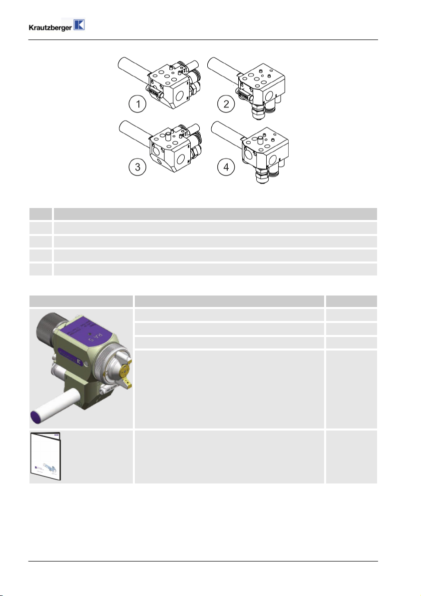
Fig. 1: Adapter variants
Pos. Description
1 Connections from behind, clamp fastening of the automatic spray gun
2 Connections from below, clamp fastening of the automatic spray gun
3 Connections from behind, screw fastening of the automatic spray gun
4 Connections from below, screw fastening of the automatic spray gun
1.2 Identification
Scope of delivery Type Item number
with adapter and conventional nozzle system 200-0319
without adapter and with conventional nozzle system 200-0321
with adapter and HVLP nozzle system * 200-0323
without adapter and with HVLP nozzle system * 200-0324
Operating manual T-Dok-449
* HVLP = High Volume, Low Pressure
Serial number
The serial number of the automatic spray gun is located on the main element. It serves as a unique
identifier.
mail@krautzberger.com, www.krautzberger.com GB–6

Automatic spray gun RA 5
ENGLISH
2 Using this operating manual
2.1 Information about the operating manual
n Knowledge of the fundamental safety instructions and safety regulations is a basic require-
ment for safe handling and defect-free operation of the product.
n This operating manual contains the most important information about enabling safe operation
of the product.
n This operating manual and, in particular, the safety instructions are to be observed by all per-
sons who work on or with the product.
n Furthermore, the rules and regulations for accident prevention in force at the respective oper-
ating site are to be observed.
2.2 Symbols in this operating manual
Safety instructions
This operating manual uses symbols to identify safety instructions. The safety instructions are preceded by signal words that indicate the severity of the hazard.
DANGER!
This combination of symbol and signal word indicates an immediate dangerous situation,
which will cause death or severe injuries if it is not averted.
WARNING!
This combination of symbol and signal word indicates a potentially dangerous situation which
can cause death or severe injuries if it is not averted.
CAUTION!
This combination of symbol and signal word indicates a potentially dangerous situation which
can cause slight injuries if it is not averted.
NOTICE!
This combination of symbol and signal word indicates a potentially dangerous situation which
can cause property and environmental damage if it is not averted.
200-0319 ■ 200-0321 ■ 200-0323 ■ 200-0324
GB–7

Operating instructions
T-Dok-449-GB-Rev.7
ENVIRONMENT!
This combination of symbol and signal word indicates potential dangers to the environment.
Tips and recommendations
This symbol highlights useful tips and recommendations as well as information for efficient
and defect-free operation.
Example for safety instructions in operating instructions
Safety instructions can refer to specific, individual operating instructions. Such safety instructions
are embedded in the operating instructions so that they do not disrupt the reading flow when performing the action. The signal words described above are used.
1. Loosen the screw.
2.
CAUTION!
Pinching hazard at the lid!
Carefully close the lid.
3. Tighten the screw.
Special safety instructions
The following symbols are used in safety instructions to draw attention to specific hazards:
Warning signs Type of danger
Warning – danger zone.
Additional markings
The following markings are used in this manual to highlight operating instructions, outcomes, lists,
references, and other elements:
Identification Explanation
Step-by-step instructions
ð
Results of procedural steps
mail@krautzberger.com, www.krautzberger.com GB–8

Automatic spray gun RA 5
ENGLISH
Identification Explanation
References to sections in this manual and other applicable documents
Lists without specified order
[Button] Operating elements (e.g. buttons, switches), display elements
(e.g. signal lights)
‘Display’ Screen elements (e.g. pushbuttons, assignment of function keys)
2.3 Personnel requirements
This manual identifies the qualifications of the personnel for the different scopes of work as listed
below:
Qualified personnel
Due to their specialised professional training, knowledge, and experience as well as knowledge of
the industry-specific standards and regulations, qualified personnel are in a position to perform
assigned tasks and to identify and avert potential risks on their own.
Specialised personnel
Due to their specialised professional training, knowledge, and experience as well as knowledge of
the industry-specific standards and regulations, qualified personnel are in a position to perform
assigned tasks and to identify and avert potential hazards on their own.
User
The user is familiar with the basic regulations on occupational safety and accident prevention.
2.4 Personal protective equipment
Personal protective equipment is used to protect persons against adverse effects on their health
and safety when working.
Personnel must wear personal protective equipment while carrying out the different tasks on and
with the machine.
In the course of regular, recurring trainings, the owner should inform operating personnel that
working without protective equipment can be detrimental to their health.
Protective equipment is selected according to the ambient conditions at the owner’s premises
and the raw materials that are used. The information provided by the material manufacturer
on the safety data sheet must be adhered to in order to ensure the proper selection of protective equipment.
The recommended personal protective equipment is described below:
200-0319 ■ 200-0321 ■ 200-0323 ■ 200-0324
GB–9

Operating instructions
T-Dok-449-GB-Rev.7
Light respiratory protection
Light respiratory protection is used as protection against hazardous dusts.
Protective gloves
Protective gloves protect hands from friction, abrasion, puncture wounds, or deeper injuries, as
well as from contact with hot surfaces.
Safety goggles
Safety goggles are used to protect the eyes from airborne components and splashes of liquid.
Protective clothing
Protective clothing are tight fitting work clothes with low tear resistance, with tight sleeves, and
without any protruding parts.
mail@krautzberger.com, www.krautzberger.com GB–10

Automatic spray gun RA 5
ENGLISH
Safety shoes
Safety shoes protect the feet against crushing, falling parts or slipping on slippery ground.
Safety helmet
The helmet protects the head from falling parts and oscillating loads on the one hand, and it can
protect it from injuries in cramped situations on the other.
200-0319 ■ 200-0321 ■ 200-0323 ■ 200-0324
GB–11

Operating instructions
T-Dok-449-GB-Rev.7
3 Safety and responsibility
3.1 Responsibility of the owner
Owner
The owner is the person, who directly operates the machine for commercial or economical purposes or who allows a third-party to use/apply it and who is responsible for the legal product stewardship for the protection of the user, the personnel or third parties.
Owner responsibilities
The machine is used in an industrial environment. The owner of the machine is therefore subject to
the obligations as stipulated by the Occupational Health and Safety Act.
In addition to the safety information in this manual, the country-specific safety, accident prevention
guidelines and environmental protection regulations, applicable at the site of implementation of the
machine must be adhered to.
Furthermore, the owner is responsible for making sure that the machine is always in perfect technical condition. Therefore, the following applies:
n The owner must ensure that the maintenance intervals described in this operating manual are
adhered to.
n The owner must have all safety equipment checked regularly for functionality and complete-
ness.
3.2 Intended use
The automatic spray gun is used to spray paints, colours, adhesives, glazes, enamels, release
agents, as well as other fluids. The nozzle size depends on the spray viscosity of the spray fluid.
The intended use also includes the compliance with all the information in this operating manual.
3.3 Specification for the operation of a complete machine
n The operation without CE-marking is prohibited.
n Prior to its use, the automatic spray gun must be assembled to form a complete machine.
n Only operate the automatic spray gun after proper fastening on a suitable carrier construction.
3.4 Predictable misuse
Any use beyond the intended use or any other use constitutes misuse.
n Only carry out the installation and start-up in accordance with the steps described in this oper-
ating manual.
n Always observe the applicable country-specific safety, accident prevention, occupational
safety, and environmental protection regulations for the area of use for the automatic spray
gun.
n Ensure that the utilised hose lines fulfil the requirements with respect to pressure, chemical,
and mechanical loads.
n Do not use sharply abrasive, chemically aggressive, very hot or very cold spray media without
first consulting with and receiving approval from Krautzberger GmbH.
n Adhere to the safety data sheets of the spray medium manufacturer.
n Only use the manufacturer's OEM parts.
n Only operate the automatic spray gun after proper fastening on a suitable carrier construction.
n Do not hold the automatic spray gun in your hand during operation.
mail@krautzberger.com, www.krautzberger.com GB–12

Automatic spray gun RA 5
ENGLISH
n Only operate the automatic spray gun while adhering to the values specified in ( Ä Chapter
13 ‘Technical data’ on page 45).
n Make sure that the connected compressed air is oil-free and free from solid matter.
n Operate the automatic spray gun with processed, dried compressed air (air quality pursuant to
DIN ISO 8573-1: quality class 4).
n Never point the compressed air at living beings.
WARNING!
Misuse of the automatic spray gun can cause dangerous situations.
No claims of any kind can be asserted due to damage resulting from misuse!
3.5 General safety instructions
WARNING!
Life threatening risk of injury or property damage through the application of hazardous
media!
The application of hazardous media can lead to death, serious injuries or property damage.
– Ensure the resistance of the machine against the medium that is to be applied.
– Always adhere to the safety data sheet of the medium that is to be applied.
CAUTION!
Risk of injury through compressed air!
Uncontrolled leaks of compressed air can lead to serious injuries!
– Prior to any work on the device, all compressed-air lines must be closed and bleed if nec-
essary.
WARNING!
Sound pressure level
Depending on the operating conditions, the sound pressure of the device may cause hearing
damage.
Take suitable action to reduce the impact of the existing sound pressure level. The owner is
responsible for the type and implementation of suitable measures, which may depend on the
local conditions.
200-0319 ■ 200-0321 ■ 200-0323 ■ 200-0324
GB–13

Operating instructions
T-Dok-449-GB-Rev.7
Outdoor operation and operation in exterior areas!
Use suitable measures to protect the device during the operation from environmental impacts
in an exterior area through:
– Moisture
– UV radiation
– Frost, etc.
3.6 Residual risks
The automatic spray gun made by Krautzberger GmbH has been manufactured based on state-ofthe-art technology and generally accepted technical safety regulations.
Nonetheless, its use can pose a threat to the life or health of users or third parties, damage the
automatic spray gun itself or cause other property damage.
n The automatic spray gun must only be used as intended.
n The automatic spray gun must only be operated in a defect-free condition.
n Any faults impacting the safety must be remedied immediately.
3.7 Course of action in an emergency
In principle, the applicable national, regional and internal company regulations concerning the
course of action in case of an emergency must be adhered to and if necessary respective
safety measures must be taken on the system owner's side.
mail@krautzberger.com, www.krautzberger.com GB–14

Automatic spray gun RA 5
ENGLISH
4 Transport, storage, and packaging
4.1 Transport
n The automatic spray gun is protected by cardboard packaging.
n The cardboard packaging can be reused for storage.
4.2 Storage
Store the automatic spray gun under the following conditions:
n Store the automatic spray gun in the original packaging.
n Do not store outside.
n Store in a dry and dust-free environment.
n Keep away from any aggressive media.
n Protect from UV radiation.
n Avoid mechanical shocks.
n Storage temperature: 15 to 40 °C.
n Relative atmospheric humidity: max. 60%.
4.3 Packaging
The automatic spray gun is packaged in accordance with the anticipated transport conditions and
the packaging needs to protect it against transport damage, corrosion, and other damage.
n Remove packaging material.
n Remove potentially present transport safety restraints.
200-0319 ■ 200-0321 ■ 200-0323 ■ 200-0324
GB–15

5 Overview
Fig. 2: Overview
1 Needle stroke setting *
2 Main element
3 Cap nut
4 Air nozzle
5 Lever for adapter plug connector *
6 Adapter
7 Retaining bolt *
F Connection for flat jet
Operating instructions
M↑ Connection for material supply (input
M↓ Connection of fluid circulation line
R Connection for round jet
ST A Connection for control air "OPEN"
ST Z Connection of control air "CLOSED"
T-Dok-449-GB-Rev.7
"M")
(output "M") *
(optional)
The connections are marked with letter abbreviations.
* optional / dependent on configuration
mail@krautzberger.com, www.krautzberger.com GB–16

Automatic spray gun RA 5
ENGLISH
6 Installation
6.1 Safety
Personnel:
Specialised personnel
n
Protective equipment:
The selection of the protective equipment depends on the installation conditions on site. Always
observe the applicable country-specific safety, accident prevention, occupational safety, and environmental protection regulations for the proper selection of the protective equipment.
WARNING!
Danger of injury due to improper assembly!
Recoil forces and vibrations occur during the operation. In case of insufficient fastening, the
automatic spray gun may come loose and cause serious injuries or property damage.
Note:
– Ensure sufficient fastening of the automatic spray gun.
CAUTION!
Risk of injury due to sharp edges!
Sharp edges and pointed corners can cause abrasions and cuts on the skin.
Note:
– Proceed cautiously when working on or near sharp edges and pointed corners.
– Wear protective gloves, if in doubt.
6.2 General installation information
Adhere to the following general information for the installation:
n Only carry out the installation and start-up in accordance with the steps described in this oper-
ating manual.
n Ensure that the utilised hose lines meet the requirements for pressure, chemical and mechan-
ical loads.
n Only operate the automatic spray gun after proper fastening on a suitable carrier construction.
n Make sure that the connected compressed air is oil-free and free from solid matter.
n Operate the automatic spray gun with processed, dried compressed air (air quality pursuant to
DIN ISO 8573-1: quality class 4).
n Vibration and recoil forces may occur on the automatic spray gun during the operation.
Ensure sufficient fastening.
n Never point the compressed air at living beings.
200-0319 ■ 200-0321 ■ 200-0323 ■ 200-0324
GB–17

Operating instructions
T-Dok-449-GB-Rev.7
6.3 Installing the automatic spray gun
Changing the installation position of the automatic spray gun
To change the installation position of the automatic spray gun, the retaining bolt ( Fig. 3/2) can
be screwed into the adapter ( Fig. 3/1) from the other side.
Fig. 3: Installing the automatic spray gun
1. Fasten the adapter ( Fig. 3/1) with the retaining bolts ( Fig. 3/2) to a suitable construction.
2.
The main element is either plugged in ( Ä Chapter 6.4.1 ‘Plugged-in design’ on page 19) or
screwed on ( Ä Chapter 6.4.2 ‘Screw-type design’ on page 20) depending on the design.
mail@krautzberger.com, www.krautzberger.com GB–18

Automatic spray gun RA 5
ENGLISH
6.4 Changing the main elements
6.4.1 Plugged-in design
Removing the main elements
Fig. 4: Removing the main elements
1. Turn the lever ( Fig. 4/3) to the unlocking position.
The unlocking and locking positions are indicated by the symbols and .
2. Press the lever ( Fig. 4/3) in and pull the main element ( Fig. 4/1) off the adapter ( Fig. 4/4).
Mounting the main elements
1. Turn the lever ( Fig. 4/3) to the unlocking position.
2. Insert the main element ( Fig. 4/1) with the clamp bolts ( Fig. 4/2) into the adapter ( Fig. 4/4)
and let them snap in.
3. Turn the lever ( Fig. 4/3) to the locking position.
200-0319 ■ 200-0321 ■ 200-0323 ■ 200-0324
GB–19

Operating instructions
T-Dok-449-GB-Rev.7
6.4.2 Screw-type design
Removing the main elements
Fig. 5: Removing the main elements
1. Loosen the screw ( Fig. 53).
2. Remove the main element ( Fig. 5/1) from the adapter ( Fig. 5/2).
Mounting the main elements
1. Push the main element ( Fig. 5/1) onto the adapter ( Fig. 5/2).
2. Screw on the main element ( Fig. 5/1) and adapter ( Fig. 5/2) with the screw ( Fig. 5/3).
6.5 Nozzle fixing (optional)
Flat jet nozzles can be adjusted to adapt to the workpiece geometry either seamlessly or in 45°
increments.
Fig. 6: Nozzle fixing
mail@krautzberger.com, www.krautzberger.com GB–20

Automatic spray gun RA 5
1. Loosen cap nut.
2. Turn flat jet nozzle anti-clockwise to the desired position.
NOTICE!
Property damage due to incorrect operation!
– The flat jet nozzle may only be turned anti-clockwise.
3. Tighten cap nut.
6.6 Connecting the automatic spray gun
See also (
Ä
Chapter 6.7 ‘Connection scheme’ on page 23).
ENGLISH
200-0319 ■ 200-0321 ■ 200-0323 ■ 200-0324
GB–21

Operating instructions
T-Dok-449-GB-Rev.7
The connections are marked with letter abbreviations.
Fig. 7: Connecting the automatic spray gun
1. Connect control air "OPEN" to "ST A" ( Fig. 7).
2. Connect control air "CLOSED" to "ST Z" ( Fig. 7) (optional, only for double controller
design).
For extremely short switching times, the automatic spray gun can also be connected
pneumatically via the optional connection "ST Z" ( Ä Chapter 6.8 ‘Preliminary air control’ on page 23).
3. Connecting the atomising air:
n Connect connection round jet to "R" ( Fig. 7).
n Connect connection flat jet to "F" ( Fig. 7).
4. Connect fluid supply to input "M↑" ( Fig. 7).
5. For design with circulation connection, connect the fluid circulation line to output "M↓" (
Fig. 7).
The fluid connections "M
↑" and "M↓" ( Fig. 7) are marked with arrows and may not be
interchanged.
mail@krautzberger.com, www.krautzberger.com GB–22

Automatic spray gun RA 5
ENGLISH
6.7 Connection scheme
Fig. 8: Connection scheme
1 Compressed-air port
2 Ball cock
3 Oil- /water separator
4 Compressed air regulator round jet
4.1 Solenoid valve round jet ON
5 Pressure jet regulator flat jet
5.1 Solenoid valve flat jet air ON
6 Solenoid valve ON
7 Solenoid valve OFF
9 Back pressure regulators
10 Container
F Flat jet air
R Round jet air
ST A Open control air
ST Z Close control air (double controller,
optional)
M Fluid connection
M Circulation connection (optional)
8 Pump
6.8 Preliminary air control
Absolutely adhere to the preliminary air control "F" and "R" according to the scheme. Otherwise,
fluid can escape non-atomised from the fluid nozzle at the beginning of the spraying procedure and
when ending the spray procedure, the nozzles can be soiled or clogged.
200-0319 ■ 200-0321 ■ 200-0323 ■ 200-0324
GB–23

Fig. 9: Preliminary air control
F Flat jet air
R Round jet air
ST A Control air ON
ST Z Control air OFF (double controller)
p Air ON
0 Air OFF
t Time
t
Time until the atomiser air is stable
1
t
Automatic spray gun in operation
2
t
Time until the nozzle is blown clean
3
Operating instructions
T-Dok-449-GB-Rev.7
mail@krautzberger.com, www.krautzberger.com GB–24

Automatic spray gun RA 5
ENGLISH
7 Operation
7.1 Safety
Personnel:
User
n
Specialised personnel
n
Protective equipment:
The selection of the personal protective equipment depends on the utilised medium of the system
owner. The information provided by the medium manufacturer indicated on the safety data sheet
must be adhered to in order to ensure the proper selection of personal protective equipment.
WARNING!
Risk of injury due to improper operation!
Improper operation can lead to serious personal injuries or property damage.
Note:
– Never point compressed air at people.
– Check the material and compressed air hose lines before each use for damage and tight
fit.
– Adhere to the spray media manufacturer's specifications in the safety data sheet.
– Make sure that the connected compressed air is oil-free and free of solid matter.
WARNING!
Life threatening risk of injury or property damage through the application of hazardous
media!
The application of hazardous media can lead to death, severe injuries or property damage.
Note:
– Ensure the resistance of the device/machine against the medium that is to be applied.
– Always adhere to the safety data sheet of the medium that is to be applied.
The owner is responsible for the presence and the up-to-date status of the safety data
sheet and the associated generation of the risk assessment of the effected workstations.
200-0319 ■ 200-0321 ■ 200-0323 ■ 200-0324
GB–25

Operating instructions
T-Dok-449-GB-Rev.7
WARNING!
Risk of fatal injury, risk of injury or property damage due to damaged or disconnected
lines!
Damaged or disconnected lines can cause death, serious injuries or property damage due to
whip-like movements and the spraying of fluids.
Note:
– Check the fluid pressure lines for damage and a tight fit prior to every work process.
7.2 General information about commissioning and start-up
Adhere to the following general information for the start-up:
n Only carry out the commissioning of the automatic spray gun pursuant to the steps described
in this operating manual.
n Check the material and compressed air hose lines for damage and tight fit before each use.
n Always observe the applicable country-specific safety, accident prevention, occupational
safety, and environmental protection regulations applicable for the area of use for the automatic spray gun.
n Do not use sharply abrasive, chemically aggressive, very hot or very cold spray media without
first consulting with and receiving approval from Krautzberger GmbH.
n Adhere to the safety data sheets of the spray medium manufacturer.
n Only operate the automatic spray gun while adhering to the values specified in (
Ä
Chapter
13 ‘Technical data’ on page 45).
n Only operate the automatic spray gun after proper fastening on a suitable carrier construction.
n Do not hold the automatic spray gun in your hand during operation.
n Never point the compressed air at living beings.
n Adhere to the operating manuals for the respective components.
7.3 Operation
To achieve optimal results, adhere to the following:
– Rinse the automatic spray gun with cleaning products before commissioning.
– Too-high air pressure causes unnecessarily high air consumption and too-strong atomi-
sation of the spray fluid.
– Too-low air pressure produces an unsatisfactory spray pattern.
– Select the lowest possible fluid pressure.
mail@krautzberger.com, www.krautzberger.com GB–26

Automatic spray gun RA 5
ENGLISH
WARNING!
Sound pressure level
Depending on the operating conditions, the sound pressure of the device may cause hearing
damage.
Take suitable action to reduce the impact of the existing sound pressure level. The owner is
responsible for the type and implementation of suitable measures, which may depend on the
local conditions.
CAUTION!
Risk of injury caused by compressed air!
Uncontrolled leaks of compressed air can lead to serious injuries.
Note:
– Check the compressed-air hoses for damage and tight fit before start-up.
– Check compressed air hoses for proper connection prior to start-up.
– Never point compressed air at living beings.
1. Make sure that the control air and atomiser air connections are not reversed.
2. Close the control air (connection "St A").
3. "Open" material supply.
Depending on the type of material supply, the "opening" of the material supply is carried out
– By opening the connection tap
– By applying pressure to the storage container
– By filling the material into a storage container (hydrostatic inherent pressure).
4. Open the control air.
The fluid is sprayed. Generally, the adjustment of the spray pattern is now required (
ð
Ä
Chapter 7.4 ‘Adjusting the spray pattern’ on page 27).
7.4 Adjusting the spray pattern
There are air and fluid nozzles in available various sizes. There are 4 different families:
n Round jet – cone-shaped jet in front of the nozzle.
n Flat jet – width-adjustable jet for flat-shaped application. Depending on the design, flat jet
nozzles can be adjusted to adapt steplessly to the workpiece geometry or in 45° increments.
200-0319 ■ 200-0321 ■ 200-0323 ■ 200-0324
GB–27

Operating instructions
T-Dok-449-GB-Rev.7
n Rotary stream – a rotary pulse produces a highly “swirled” spray jet; for difficult workpiece
geometries (angular sections etc.).
n Full-cone rotary stream – a rotary pulse produces a highly “swirled” spray jet; for difficult
workpiece geometries (back cuts, etc.).
Adjust the spray pattern with the following measures:
n Change the atomiser air pressure.
n Change the pressure of the spray fluid.
n Select another nozzle size.
n Adjust the needle stroke (optional) (
Ä
Chapter 7.5 ‘Adjusting the needle stroke’ on page 28).
Too-high air pressure causes unnecessarily high air consumption and too-strong atomisation
of the spray fluid. It is recommended that you first adjust the spray pattern by varying the air
and spray fluid pressure. If you cannot achieve satisfactory results this way, you should
experiment with other nozzle sizes.
To reduce overspray and the concentration of harmful substances when coating, observe the following points:
n Guide the spray jet vertically to the surface
n Adjust the spray jet to suit the geometry of the workpiece
n The spray gun should be as close to the workpiece as possible
n Always spray in the extraction direction
7.5 Adjusting the needle stroke
Fig. 10: Adjusting the needle stroke
1. Pull out the needle stroke adjustment screw ( Fig. 10/1) until it loosens.
2. Adjust the needle stroke by turning the needle stroke adjustment screw ( Fig. 10/1).
3. Push in the needle stroke adjustment screw ( Fig. 10/1) until it tightens again.
mail@krautzberger.com, www.krautzberger.com GB–28

Automatic spray gun RA 5
ENGLISH
7.6 Shutting down
7.6.1 Temporary shut-down
Fig. 11: Shutting down
End the spray procedure by switching off the control air (connection "St A", Fig. 11/1).
7.6.2 Long-term shut-down
1. End the spray procedure by switching off the control air (connection "St A", Fig. 11/1).
2. Close the material supply and switch off the fluid pressure pump or the pressure container if
necessary.
3.
If necessary, clean the automatic spray gun ( Ä Chapter 8.3 ‘Cleaning the automatic spray
gun’ on page 31).
200-0319 ■ 200-0321 ■ 200-0323 ■ 200-0324
GB–29

Operating instructions
T-Dok-449-GB-Rev.7
8 Maintenance
8.1 Safety
Personnel:
Specialised personnel
n
Protective equipment:
The selection of the protective equipment depends on the maintenance conditions on site and the
medium utilized by the system owner. The applicable country-specific safety, accident prevention,
occupational safety, and environmental protection regulations must adhered to for the proper
selection of the protective equipment and the information given by the spray media manufacturer
on the safety data sheet must be taken into consideration.
WARNING!
Risk of injury through the use of incorrect spare parts!
The use of incorrect or defective spare parts can cause hazards for the personnel as well as
damage, malfunctions or complete failure.
– Only use OEM parts from Krautzberger or Krautzberger-approved spare parts.
– In case of questions, always contact our Customer Care department.
CAUTION!
Risk of injury through compressed air!
Uncontrolled leaks of compressed air can lead to serious injuries!
– Prior to any work on the device, all compressed-air lines must be closed and bleed if nec-
essary.
Hose and pipelines
Even with intended use by environmental influences, the service life of hose lines and pipelines is limited. For the sake of prevention, all hose and pipelines should be replaced regularly
according to their load.
8.2 Maintenance schedule
The following sections describe the maintenance work that is required for optimal and fault-free
operation of the automatic spray gun. Check wearing parts such as seals, nozzles and needles at
regular intervals. The level of wear depends on the abrasiveness of the spray fluid used. Escaping
air and spray fluid as well as the deterioration of the spray pattern are signs that parts are worn.
Contact Krautzberger Customer Care with any questions on maintenance work and maintenance
intervals.
mail@krautzberger.com, www.krautzberger.com GB–30

Automatic spray gun RA 5
ENGLISH
Interval Maintenance work Personnel
before performing any
maintenance work
Clean the automatic spray gun ( Ä Chapter 8.3
‘Cleaning the automatic spray gun’ on page 31)
if needed Change material nozzle and air nozzle (
Ä
Chapter 8.4 ‘Changing the material nozzle
Specialised personnel
Specialised personnel
and the air nozzle’ on page 33)
Change fluid needle ( Ä Chapter 8.5 ‘Changing
Specialised personnel
the fluid needle’ on page 34)
Change needle seals ( Ä Chapter 8.6
Specialised personnel
‘Changing the needle seals’ on page 37)
Always replace material nozzle and material needle at the same time ( Ä Chapter 8.4
‘Changing the material nozzle and the air nozzle’ on page 33) and ( Ä Chapter 8.5 ‘Changing
the fluid needle’ on page 34).
8.3 Cleaning the automatic spray gun
WARNING!
Risk of injury due to improper cleaning!
– Adhere to the safety data sheets of the cleaning product manufacturer.
– Do not fully immerse the automatic spray gun in a cleaning product.
200-0319 ■ 200-0321 ■ 200-0323 ■ 200-0324
GB–31

Operating instructions
1.
Interrupt the operation ( Ä Chapter 7.6 ‘Shutting down’ on page 29).
T-Dok-449-GB-Rev.7
2. Switch off the system and secure it against being switched on again.
3. Connect cleaning product to input "M".
For design with circulation connection (optional), connect the fluid circulation line to output
"M".
The fluid connections are marked with arrows and must not be interchanged.
4. Switch on the compressed air supply.
5. Where applicable, switch on fluid pressure pump or pressure container for cleaning
product.
6. Begin the spraying procedure by switching on the control air (connection "ST A").
7. Spray until the cleaning product runs clear.
8. Interrupt the supply of cleaning product by switching off the fluid pressure pump or the pres-
sure container.
9. Blow out cleaning product residue by briefly switching on the control air.
10. Switch off the compressed air supply and secure it against a restart.
11. Clean the outside of the device with a cloth dipped in cleaning product.
12.
Remove fluid and air nozzle ( Ä Chapter 8.4 ‘Changing the material nozzle and the air
nozzle’ on page 33) and clean with a soft brush. Do not use hard or sharp-edged objects.
We recommend our brush set. See the last page for contact information.
13. Slightly grease sliding parts with special Krautzberger grease.
The special grease can be purchased from Krautzberger GmbH (contact data see last page).
mail@krautzberger.com, www.krautzberger.com GB–32

Automatic spray gun RA 5
8.4 Changing the material nozzle and the air nozzle
Removing the nozzles
Fig. 12: Removing the nozzles
1. Loosen cap nut ( Fig. 12/4).
2. Remove the air nozzle ( Fig. 12/3).
3. Unscrew the fluid nozzle ( Fig. 12/2) with a flat spanner.
Always change the fluid nozzle and needle together ( Ä Chapter 8.5 ‘Changing the
fluid needle’ on page 34).
ENGLISH
Attaching the nozzles
1.
The air distributor ring ( Fig. 12/1) is only required for flat jet nozzles. When fitting the
automatic spray gun with round or flat jet nozzles, the air distributor ring ( Fig. 12/1) is
not mounted but it is included in the scope of delivery.
If necessary, make sure that the air distributor ring ( Fig. 12/1) is positioned correctly.
2. Screw on the fluid nozzle ( Fig. 12/2) with a flat spanner.
3. Attach the air nozzle ( Fig. 12/3) and tighten it with the cap nut ( Fig. 12/4).
200-0319 ■ 200-0321 ■ 200-0323 ■ 200-0324
GB–33

Operating instructions
T-Dok-449-GB-Rev.7
8.5 Changing the fluid needle
Removing the fluid needle
Fig. 13: Removing fluid needle
1. Loosen the screws ( Fig. 13/1) slightly.
2.
Locking piece ( Fig. 13/6) (optional) is under spring force.
Turn the locking piece ( Fig. 13/6) (or depending on the design of the cover) slightly anticlockwise and remove it.
3. Remove the pressure spring ( Fig. 13/4) and if necessary the seal ( Fig. 13/5) (only for
double controller).
4. Screw a screw ( Fig. 13/1) into the control piston ( Fig. 13/7).
5. Pull out the control piston ( Fig. 13/7) from the main element ( Fig. 13/8) using the screw (
Fig. 13/1).
Fig. 14: Removing fluid needle
mail@krautzberger.com, www.krautzberger.com GB–34

Automatic spray gun RA 5
6.
CAUTION!
Risk of injury due to fluid needles!
Remove the fluid needle ( Fig. 14/4) from the control piston ( Fig. 14/3).
7.
WARNING!
Risk of injury through the use of incorrect spare parts!
Check the condition of the seals ( Fig. 14/1 and 2), replace the seals if necessary.
ENGLISH
200-0319 ■ 200-0321 ■ 200-0323 ■ 200-0324
GB–35

Operating instructions
T-Dok-449-GB-Rev.7
Attaching the fluid needle
Fig. 15: Attaching the fluid needle
1.
CAUTION!
Risk of injury due to fluid needles!
Hook a new fluid needle ( Fig. 15/2) into the control piston ( Fig. 15/3).
2. Ensure that the needle stroke adjustment ( Fig. 15/4) (optionally) is relaxed. If necessary,
release the pressure by turning anti-clockwise.
3. Push the fluid needle ( Fig. 15/2) with the control piston ( Fig. 15/3) into the main element (
Fig. 15/1).
Fig. 16: Attaching the fluid needle
4. Unscrew the screw ( Fig. 16/2) from the control piston ( Fig. 16/6) and screw it into the main
element again ( Fig. 16/7).
5. Make sure that the seal ( Fig. 16/4) is seated properly.
6. Press in the pressure spring ( Fig. 16/3) with the locking part ( Fig. 16/5).
7. Hook the locking part ( Fig. 16/5) into the screws ( Fig. 16/1).
8. Tighten the screws ( Fig. 161) evenly.
mail@krautzberger.com, www.krautzberger.com GB–36

Automatic spray gun RA 5
ENGLISH
9. After assembly, check the tight fit of all parts.
10. Check moving parts to make sure they run easily.
8.6 Changing the needle seals
Removing the needle seals
1.
Remove the material needle ( Ä Chapter 8.5 ‘Changing the fluid needle’ on page 34).
Fig. 17: Removing the needle seals
2. Unscrew the clamping screw ( Fig. 17/4) with a box spanner.
3. Remove the slotted ring ( Fig. 17/5) from the clamping screw ( Fig. 17/4).
4. Remove the bracket ( Fig. 17/2) and slotted ring ( Fig. 17/1) from the bracket ( Fig. 17/2).
5. Check the condition of the O-ring ( Fig. 17/3), replace if necessary.
6. Replace the slotted rings ( Fig. 17/1 and 5).
200-0319 ■ 200-0321 ■ 200-0323 ■ 200-0324
GB–37

Operating instructions
T-Dok-449-GB-Rev.7
Inserting the needle seals
1.
WARNING!
Risk of injury through the use of incorrect spare parts!
Insert the slotted ring ( Fig. 17/1) into the bracket ( Fig. 17/2). Here, make sure that the
slotted ring ( Fig. 18/1) is in the correct position.
2. Make sure that the O-ring ( Fig. 17/3) fits correctly on the clamping screw ( Fig. 17/4).
Ensure that the slotted ring ( Fig. 17/5) is correctly positioned in the clamping screw (
Fig. 17/4).
Fig. 18: Installation state
3. Place the bracket ( Fig. 17/2) with the slotted ring ( Fig. 17/1) onto the material needle and
then slide it into the main element.
4. Screw in the bracket with the socket wrench until you feel gentle resistance.
5. Press the material needle with the material nozzle firmly into the main element ( Fig. 17/6).
6. Tighten the complete package with the socket wrench.
mail@krautzberger.com, www.krautzberger.com GB–38

Automatic spray gun RA 5
ENGLISH
9 Troubleshooting
Personnel:
Qualified personnel
n
If the fault is not included in the following tables or if it cannot be eliminated with the measures
described, contact Krautzberger Customer Care.
Spray pattern Error Cause Remedy
Normal flat jet spray pattern
Spray pattern too
heavy towards the top
and towards the
bottom
Spray pattern concentrated on the left or
right side
Heavy application in
the centre of the spray
pattern
Split spray pattern
Spray pattern too thin
n Dirty air nozzle
n Dirty fluid nozzle
Clean nozzles (
Ä
Chapter 8.3
‘Cleaning the automatic spray gun’
on page 31)
n Dirty air nozzle
n Dirty fluid nozzle
Clean nozzles (
Ä
Chapter 8.3
‘Cleaning the automatic spray gun’
on page 31)
n Too much mate-
rial
n Reduce material
supply
n Material too thick n Thin material
n Insufficient mate-
rial
n Flat jet air pres-
sure too high
n Cap nut loose
n Increase material
supply
n Reduce flat jet air
pressure
Tighten cap nut
200-0319 ■ 200-0321 ■ 200-0323 ■ 200-0324
GB–39

Operating instructions
Spray pattern Error Cause Remedy
Fluid jet comes out in
spurts or rapid bursts
n Insufficient mate-
rial supply
n Increase material
supply
n Blocked fluid path n Clean
n Loose or dam-
aged fluid nozzle
n Tighten or replace
( Ä Chapter 8.4
‘Changing the
material nozzle
and the air nozzle’
on page 33)
n Worn needle seal n Replace needle
seal ( Ä Chapter
8.6 ‘Changing the
needle seals’
on page 37)
Leakage on the
clamping screw
n Needle seal
defective
n Replace needle
seal ( Ä Chapter
8.6 ‘Changing the
needle seals’
on page 37)
Fluid nozzle drips
n Worn or damaged
fluid needle
n Change fluid
needle (
Ä
‘Changing the
fluid needle’
on page 34)
n Dirty or damaged
fluid nozzle
n Clean (
Ä
‘Cleaning the
automatic spray
gun’ on page 31)
or replace fluid
nozzle (
Ä
‘Changing the
material nozzle
and the air nozzle’
on page 33)
- Spray pattern change
after reassembly.
Atomisers for round
n Air distributor ring
installed wrong
way
n Remove air dis-
tributor ring and
install correctly
and flat jets can no
longer be regulated
separately
T-Dok-449-GB-Rev.7
Chapter 8.5
Chapter 8.3
Chapter 8.4
mail@krautzberger.com, www.krautzberger.com GB–40

Automatic spray gun RA 5
9.1 Customer Care
Krautzberger GmbH
Customer service
Stockbornstr. 13
65343 Eltville am Rhein
+49 6123 - 698151
customercare@krautzberger.com
ENGLISH
200-0319 ■ 200-0321 ■ 200-0323 ■ 200-0324
GB–41

Operating instructions
10 Spare parts
– Only use OEM parts from Krautzberger or Krautzberger-approved spare parts.
– In case of questions, always contact our Customer Care department.
Spare parts order – General
To make spare part ordering easier, please provide the following information:
– Serial number
– Model / product name
– Designation
– Item number according to spare parts list
– Quantity
– Desired shipping method (post, freight, sea, air, express)
– Delivery address
T-Dok-449-GB-Rev.7
A complete spare part overview is available on the website of Krautzberger GmbH:
www.krautzberger.de
mail@krautzberger.com, www.krautzberger.com GB–42

Automatic spray gun RA 5
ENGLISH
11 Accessories
A wide range of accessories is available for the automatic spray gun. For further information, visit
us on the Internet (www.krautzberger.com) or contact your Krautzberger specialist dealer, consultant or our office staff. Here are a few examples:
n Air nozzles
n Fluid needles
n Fluid nozzles
n Arm extension for robot
n etc.
200-0319 ■ 200-0321 ■ 200-0323 ■ 200-0324
GB–43

Operating instructions
T-Dok-449-GB-Rev.7
12 Disassembly and disposal
12.1 Safety
Personnel:
Qualified personnel
n
Protective equipment:
The selection of the protective equipment depends on the environmental conditions at the site of
the owner and the coating material that is used. To ensure the proper selection of personal protective equipment, the information provided by the spray material manufacturer indicated on the
safety data sheet must be adhered to.
12.2 Disassembly
WARNING!
Risk of injury due to improper disassembly!
Prior to starting the disassembly:
n Switch off the device and secure it against a restart.
n Physically disconnect the entire power supply from the device, and discharge any energy
stored in the machine.
n Remove and dispose of operating and auxiliary material as well as remaining processing
materials in an environmentally friendly manner.
Afterwards, properly clean components and modules and take them apart in compliance with applicable local occupational health & safety regulations as well as environmental protection regulations.
12.3 Disposal
ENVIRONMENT!
Danger to the environment due to incorrect disposal!
Incorrect disposal may cause dangers to the environment.
If no return or disposal agreement has been made, recycle the dismantled parts:
n Scrap metals.
n Recycle plastic components.
n Sort remaining components based on the respective material and dispose of them accord-
ingly.
n Properly dispose of potential spray media residue separately from the device.
If in doubt, obtain information about environmentally-appropriate disposal from the local authorities
or specialised disposal companies.
mail@krautzberger.com, www.krautzberger.com GB–44

Automatic spray gun RA 5
ENGLISH
13 Technical data
13.1 Dimensions and weight
Specification Value Unit
Width 94.5 mm
Height max. 86.5 mm
Length 113 mm
Connection for spray fluid (M) female * G1/8 "
Connection for atomiser air (R, F) female * G1/8 "
Connection for control air (St) female * M5 -
Weight aluminium design 0.55 kg
Weight stainless steel housing 0.97 kg
* female = internal thread
13.2 General specifications
Specification Value Unit
Working pressure control air (St) max. 8 bar
Working pressure spray fluid (M) max. 12 bar
Working pressure atomiser air (R, F) max. 8 bar
Sound pressure level depends on the nozzle approx. 73 - 96 dB(A)
Spray medium temperature max. 50 °C
13.3 Dimensions
Fig. 19: Dimensions
200-0319 ■ 200-0321 ■ 200-0323 ■ 200-0324
GB–45

Operating instructions
14 Declaration of incorporation
T-Dok-449-GB-Rev.7
Fig. 20: Declaration of incorporation
mail@krautzberger.com, www.krautzberger.com GB–46

Automatic spray gun RA 5
ENGLISH
15 Notes
______________________________________________________________________________
______________________________________________________________________________
______________________________________________________________________________
______________________________________________________________________________
______________________________________________________________________________
______________________________________________________________________________
______________________________________________________________________________
______________________________________________________________________________
______________________________________________________________________________
______________________________________________________________________________
______________________________________________________________________________
______________________________________________________________________________
______________________________________________________________________________
______________________________________________________________________________
______________________________________________________________________________
______________________________________________________________________________
______________________________________________________________________________
______________________________________________________________________________
______________________________________________________________________________
______________________________________________________________________________
______________________________________________________________________________
______________________________________________________________________________
______________________________________________________________________________
______________________________________________________________________________
______________________________________________________________________________
______________________________________________________________________________
______________________________________________________________________________
______________________________________________________________________________
______________________________________________________________________________
______________________________________________________________________________
______________________________________________________________________________
______________________________________________________________________________
200-0319 ■ 200-0321 ■ 200-0323 ■ 200-0324
GB–47

Operating instructions
T-Dok-449-GB-Rev.7
______________________________________________________________________________
______________________________________________________________________________
______________________________________________________________________________
______________________________________________________________________________
______________________________________________________________________________
______________________________________________________________________________
______________________________________________________________________________
______________________________________________________________________________
______________________________________________________________________________
______________________________________________________________________________
______________________________________________________________________________
______________________________________________________________________________
______________________________________________________________________________
______________________________________________________________________________
______________________________________________________________________________
______________________________________________________________________________
______________________________________________________________________________
______________________________________________________________________________
______________________________________________________________________________
______________________________________________________________________________
______________________________________________________________________________
______________________________________________________________________________
______________________________________________________________________________
______________________________________________________________________________
______________________________________________________________________________
______________________________________________________________________________
______________________________________________________________________________
______________________________________________________________________________
______________________________________________________________________________
______________________________________________________________________________
______________________________________________________________________________
______________________________________________________________________________
______________________________________________________________________________
mail@krautzberger.com, www.krautzberger.com GB–48

Automatic spray gun RA 5
ENGLISH
______________________________________________________________________________
______________________________________________________________________________
______________________________________________________________________________
______________________________________________________________________________
______________________________________________________________________________
______________________________________________________________________________
______________________________________________________________________________
______________________________________________________________________________
______________________________________________________________________________
______________________________________________________________________________
______________________________________________________________________________
______________________________________________________________________________
______________________________________________________________________________
______________________________________________________________________________
______________________________________________________________________________
______________________________________________________________________________
______________________________________________________________________________
______________________________________________________________________________
______________________________________________________________________________
______________________________________________________________________________
______________________________________________________________________________
______________________________________________________________________________
______________________________________________________________________________
______________________________________________________________________________
______________________________________________________________________________
______________________________________________________________________________
______________________________________________________________________________
______________________________________________________________________________
______________________________________________________________________________
______________________________________________________________________________
______________________________________________________________________________
______________________________________________________________________________
______________________________________________________________________________
200-0319 ■ 200-0321 ■ 200-0323 ■ 200-0324
GB–49

Operating instructions
T-Dok-449-GB-Rev.7
16 Index
C
Cleaning ......................................................31
Complete machine ................................................12
Connection values ................................................45
D
Delivery ......................................................15
Dimensions ....................................................45
Disassembly ...................................................44
E
Emissions .....................................................45
F
Function description ...............................................5
H
Health .......................................................13
I
Item number ....................................................6
M
Measurements ..................................................45
Model plate .....................................................6
N
Noise emission ..................................................45
O
Operating pressures ...............................................45
Owner .......................................................12
P
Personnel ......................................................9
Pictograms .....................................................7
R
Recycling .....................................................44
S
Serial number ...................................................6
Sound pressure level ..............................................45
Storage ......................................................15
Symbols .......................................................7
mail@krautzberger.com, www.krautzberger.com GB–50

Automatic spray gun RA 5
ENGLISH
T
Temperature specifications ..........................................45
Troubleshooting table ..............................................39
U
User qualification .................................................9
W
Weight .......................................................45
200-0319 ■ 200-0321 ■ 200-0323 ■ 200-0324
GB–51


Krautzberger GmbH
Stockbornstrasse 13
D-65343 Eltville am Rhein, Germany
Hotline: +49 (0) 6123 698-222
Head Office: +49 (0) 6123 698-0
Fax: +49 (0) 6123 698-200
Email: mail@krautzberger.com
Internet: www.krautzberger.com
© Krautzberger GmbH 2017
© Krautzberger GmbH 2017
 Loading...