


GB
Operating instructions
Diaphragm pump MP-520
Article No. ■ 200-0216 ■ 200-0330
Original operating instructions
T-Dok-397-EN-Rev.0-
web

Thank you for selecting a Krautzberger product.
This product has been manufactured according to the latest manufacturing procedures and with
extensive quality assurance measures. We promise you a product of the highest quality
If you have questions, desires or suggestions, please contact us; we are always glad to assist you.
Information about the topic of Ex protection
Many of our competitors have been identifying their products with the Ex symbol for a while now.
Krautzberger does not do this.
We construct and manufacture our products according the currently-valid guidelines.
If the marking on the product is required, then it is affixed on the product as the result of the necessary analysis of ignition sources. If no marking is affixed, then the required analysis of ignition
sources as well as previous experience with the assessment of the applicability of the products in
the Ex area showed that the product described in these operating instructions provides no potential
source of ignition with the exception of the electrostatic charge.
Taking into account the potential equalisation (due to proper earthing), use in the Ex area is admissible according to the currently-valid guidelines.
mail@krautzberger.com, www.krautzberger.com GB–2

Diaphragm pump MP-520
ENGLISH
Table of contents
1 Safety................................................................................................................................... 4
1.1 Proper use................................................................................................................... 5
1.2 Personnel requirements............................................................................................... 5
1.3 Personal safety equipment and clothing...................................................................... 6
1.4 Disposal....................................................................................................................... 6
2 Technical data..................................................................................................................... 7
2.1 Dimensions.................................................................................................................. 7
2.2 General specifications................................................................................................. 8
2.3 Material delivery properties.......................................................................................... 8
3 Structure and function..................................................................................................... 10
3.1 Overview.................................................................................................................... 10
3.2 Functional description................................................................................................ 10
4 Installation and connection............................................................................................. 11
4.1 Installing the diaphragm pump................................................................................... 11
4.2 Connection example.................................................................................................. 12
4.3 Connecting the diaphragm pump............................................................................... 13
5 Operation........................................................................................................................... 14
5.1 Commissioning.......................................................................................................... 15
5.2 Stopping operation..................................................................................................... 15
6 Maintenance...................................................................................................................... 16
6.1 Maintenance schedule............................................................................................... 16
6.2 Maintenance work...................................................................................................... 17
7 Faults................................................................................................................................. 20
7.1 Fault table.................................................................................................................. 20
7.2 Replace the pressure controller/control valve............................................................ 22
8 Spare parts/accessories.................................................................................................. 26
8.1 Diaphragm pump spare parts.................................................................................... 26
8.2 Accessories............................................................................................................... 28
9 EU declaration of conformity.......................................................................................... 29
Article No. ■ 200-0216 ■ 200-0330
GB–3

Operating instructions
T-Dok-397-EN-Rev.0-
1 Safety
Safety instructions
DANGER!
This combination of symbol and signal word indicates an immediately dangerous situation
which causes death or severe injuries if it is not avoided.
WARNING!
This combination of symbol and signal word indicates a possibly dangerous situation which
can cause death or severe injuries if it is not avoided.
CAUTION!
This combination of symbol and signal word indicates a possibly dangerous situation which
can cause slight injuries if it is not avoided.
web
NOTICE!
This combination of symbol and signal word indicates a possibly dangerous situation which
can cause property and environmental damage if it is not avoided.
This symbol highlights useful tips and recommendations as well as information for efficient
and fault-free operation.
Symbol Explanation
Indicates step-by-step instructions.
ð
Indicates a condition or an automatic sequence as the result of an action.
Indicates references to sections of these instructions and other applicable
documents.
Indicates enumerations and list entries without a specified sequence.
mail@krautzberger.com, www.krautzberger.com GB–4

Diaphragm pump MP-520
ENGLISH
1.1 Proper use
The MP-520 diaphragm pump is a pump operated with compressed air and is used exclusively
n for the conveying of liquid and low-viscosity coatings from non-pressurised storage con-
tainers.
n for the supply of material to spray guns. automatic spray guns, metering devices and similar.
It is mainly used for painting and coating operations.
Proper use also includes observance of all details in these instructions.
Any use beyond the proper use or any other use counts as misuse.
WARNING!
Danger due to misuse!
Misuse of the diaphragm pump can cause dangerous situations.
– Always observe the valid safety, accident prevention, occupational safety and environ-
mental protection regulations valid for the area of application of the diaphragm pump.
– Only use sharply abrasive, chemically-aggressive, very hot or very cold spray media in
consultation with Krautzberger GmbH.
– Only use the manufacturer's original spare parts.
– Only operate the diaphragm pump while adhering the values specified in the
2 ‘Technical data’ on page 7.
Ä
Chapter
– Only operate the diaphragm pump after proper fastening on a suitable carrier construc-
tion.
– Do not hold the diaphragm pump in your hand during operation.
– Adhere to the spray media manufacturer's safety data sheets.
– Do not use the diaphragm pump in the food or pharmaceutical sectors.
No claims of any type can be asserted due to damage resulting from misuse.
1.2 Personnel requirements
Ensure the use of the device by skilled employees! Only skilled employees can independently
detect and avoid possible dangers during use based on their professional training, experience and
knowledge of the relevant regulations.
Article No. ■ 200-0216 ■ 200-0330
GB–5

Operating instructions
T-Dok-397-EN-Rev.0-
1.3 Personal safety equipment and clothing
When using the device, always wear breathing, eye and ear protection.
Only wear approved protective gloves during cleaning work with solvents.
1.4 Disposal
When the useful life of the device has been exhausted, dispose of it in commercial waste. In order
to prevent damage to the environment, dispose of any remains of spray fluid properly separately
from the device.
web
mail@krautzberger.com, www.krautzberger.com GB–6

Diaphragm pump MP-520
2 Technical data
2.1 Dimensions
ENGLISH
Fig. 1: Dimensions in mm
Article No. ■ 200-0216 ■ 200-0330
GB–7

Operating instructions
T-Dok-397-EN-Rev.0-
2.2 General specifications
Data Value Unit
Delivery rate (with respect to water, free flow) 15 l/min
Material connection (outlet) 3/4" external thread Inches
Max. temperature of the coating material used 0 ... +50 °C
Max. pressure 8 bar
Max. permitted operating pressure 8 bar
Compressed air connection (hose sleeve) 8/9 mm
Min. air intake pressure 4 bar
Max. air intake pressure 8 bar
Max. stroke (double strokes) 120 DS/min
Recommended number of strokes (double strokes) 100 DS/min
Weight 9.0 kg
Noise pressure level (at 8 bar and100 DS) 80 dB(A)
Transformation ratio 1:1
Compressed air supply oil-free, filtered
web
2.3 Material delivery properties
Material Suitability
Paint (with solvent) good
Water-based paint, dispersions, wood preservatives good
Water good
Oils, heating oils, diesel fuel good
Emulsions, soap, detergents good
Alcohol, glazes, latex limited
Lime sludge limited
Cell and fibre materials unsuitable
Sludge, mash, pastes unsuitable
mail@krautzberger.com, www.krautzberger.com GB–8

Diaphragm pump MP-520
ENGLISH
In case of doubt about suitability of materials not listed, please enquire. In special cases we
will determine the suitability in an experiment.
Article No. ■ 200-0216 ■ 200-0330
GB–9

Operating instructions
3 Structure and function
3.1 Overview
Fig. 2: Overview
1 Material intake connection (material entry)
2 Compressed air connection
3 Pressure gauge
4 Material pressure connection (material outlet)
5 Surge tank connection
6 Material pressure connection 2 (material outlet)
7 Compressed air controller
8 Barrel cover mount (optional)
T-Dok-397-EN-Rev.0-
web
3.2 Functional description
The pressure required at the extraction point can be adjusted continuously variably using the compressed air controller (Fig. 2/7). As soon as the set material pressure has been reached, the diaphragm pump switches off automatically. The material pressure is maintained until material is
extracted at the extraction point. The diaphragm pump switches on automatically and keeps the
set material pressure constant.
mail@krautzberger.com, www.krautzberger.com GB–10

Diaphragm pump MP-520
ENGLISH
4 Installation and connection
4.1 Installing the diaphragm pump
Fig. 3: Installation
1. Install the pump directly on a wall or supporting structure using the elongated holes
(Fig. 3/3) with suitable fastening screws. In the process, make sure that the material suction
connection (Fig. 3/1) points vertically downwards after installation.
The diaphragm pump can be fitted directly to a barrel cover using the optional barrel cover
mount (Fig. 3/4).
2. Connect the earthing with the earthing screw (Fig. 3/2).
WARNING!
Risk of fatal injury from electrostatic charge.
Electrostatic charges can cause shocks and sparks and thus explosions.
– Ensure proper earthing.
– Use conductive hose line (< 1 MW).
Article No. ■ 200-0216 ■ 200-0330
GB–11

Operating instructions
4.2 Connection example
Fig. 4: Connection example
1 Air controller unit with filter
2 MP-520 diaphragm pump
3 Surge tank
4 Ball cock
5 Screw connection
6 Material filter
7 Reducer
8 Material controller
9 Low-pressure material hose with fittings
10 Spray gun
11 Intake hose with suction cage
T-Dok-397-EN-Rev.0-
web
mail@krautzberger.com, www.krautzberger.com GB–12

Diaphragm pump MP-520
4.3 Connecting the diaphragm pump
Fig. 5: Connection
1. Connect the material intake hose to the material intake connection (Fig. 5/1).
2. Connect the compressed air supply to the compressed air port (Fig. 5/2).
ENGLISH
The compressed air supply must be dry, free of oil and secured by a pressure relief
valve.
3. Connect the material pressure hose to the material pressure connection (material outlet)
(Fig. 5/3 or 5).
4. If necessary, connect the surge tank to the connection (Fig. 5/4).
5. Check that all connections are firmly in place.
Article No. ■ 200-0216 ■ 200-0330
GB–13

Operating instructions
T-Dok-397-EN-Rev.0-
5 Operation
WARNING!
Risk of injury due to improper operation!
– Only perform operation in accordance with the steps shown in these operating instruc-
tions.
– Never point the compressed air at people.
– Check the material and compressed air hose lines before each use for damage and tight
fit.
– Make sure that the hose lines used fulfil the requirements with respect to pressure,
chemical and mechanical loads.
– Make sure that the connected compressed air is oil-free and free of solid matter.
– Adhere to the spray media manufacturer's specifications in the safety data sheet.
web
mail@krautzberger.com, www.krautzberger.com GB–14
Diaphragm pump MP-520
ENGLISH
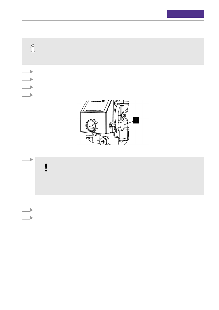
5.1 Commissioning
Adhere to the operating instructions for the respective components.
1. Check the material and compressed air lines to make sure they are whole and fit tightly.
2. Switch on the compressed air supply.
3. Make sure that there is air pressure of 4 to 8 bar.
4. Make sure that the material intake hose is dipped into the material.
Fig. 6: Compressed air controller
5.
NOTICE!
Risk of increased wear if run in idle.
During initial commissioning there is still air in the diaphragm pump and the supply
lines. In idle mode the diaphragm pump is subject to particularly high levels of wear.
To bleed the pressure controller (Fig. 6/1), first set a low air pressure.
6. Activate the extraction point (e.g. manual spray gun) until material escapes.
7. After successful bleeding, set the desired material pressure with the pressure controller.
5.2 Stopping operation
See Ä Chapter 6.2.1 ‘Cleaning the diaphragm pump’ on page 17.
Article No. ■ 200-0216 ■ 200-0330
GB–15

Operating instructions
T-Dok-397-EN-Rev.0-
web
6 Maintenance
Hose and pipelines
The service life of hose and pipelines is limited even with proper use by environmental influences. For the sake of prevention, all hose and pipelines should be replaced regularly
according to their load.
6.1 Maintenance schedule
The following sections describe the maintenance work that is required for optimal and fault-free
operation of the device.
Check wearing parts such as seals at regular intervals. The level of wear depends on the abrasiveness of the spray fluid used. Escaping air and spray fluid are signs that parts are worn. In case of
questions about maintenance work and intervals, contact the manufacturer; see contact data on
the last page.
Interval Maintenance work Personnel
After each use
When required
Clean diaphragm pump (Ä Chapter 6.2.1 ‘Cleaning the
diaphragm pump’ on page 17)
Replace valve parts (Ä Chapter 6.2.2 ‘Replacing valve
parts’ on page 18)
Replace diaphragms (Ä Chapter 6.2.3 ‘Replacing diaphragms’ on page 19)
Qualified personnel
Qualified personnel
Qualified personnel
mail@krautzberger.com, www.krautzberger.com GB–16

Diaphragm pump MP-520
ENGLISH
6.2 Maintenance work
6.2.1 Cleaning the diaphragm pump
WARNING!
Danger of injury due to improper cleaning!
– Observe the safety data sheets of the detergent manufacturer.
– Do not use any halogenated detergents.
1. Interrupt the compressed air supply in a suitable location (e.g. shut-off device).
2. Dip the material intake hose into a suitable detergent.
3. Switch on the compressed air supply.
4. Rinse out the diaphragm pump by activating the extraction point until only detergent liquid
escapes.
5. Disconnect the compressed air supply.
6. If necessary, activate the extraction point again and depressurise the pump.
7. Leave detergent liquid in the pump.
8. Clean the outside of the device with a cloth dipped in detergent.
Article No. ■ 200-0216 ■ 200-0330
GB–17

Operating instructions
6.2.2 Replacing valve parts
1.
Clean diaphragm pump (Ä Chapter 6.2.1 ‘Cleaning the diaphragm pump’ on page 17).
2. Make sure that the compressed air supply is switched off.
3. If necessary, depressurise the material by activating the extraction point.
T-Dok-397-EN-Rev.0-
web
Fig. 7: Valve parts
4. Unscrew the hexagon screws (Fig. 7/1).
5. Remove the bridge (Fig. 7/2).
6. Remove the flat seals (Fig. 7/3), ball cages (Fig. 7/4), valve balls (Fig. 7/5) and the valve
seat (Fig. 7/6).
7. Check all parts for damage and wear and replace them as necessary.
8.
Replace diaphragms (
Ä
Chapter 6.2.3 ‘Replacing diaphragms’ on page 19).
9. Clean the valve housing.
10. Install all valve parts (Fig. 7/3 to 6) in the sequence shown.
11. Attach the bridge (Fig. 7/2).
12. Screw the hexagon screws (Fig. 7/1) tight.
13.
Clean the diaphragm pump (Ä Chapter 6.2.1 ‘Cleaning the diaphragm pump’ on page 17)
and perform a test run (Ä Chapter 5.1 ‘Commissioning’ on page 15).
mail@krautzberger.com, www.krautzberger.com GB–18

Diaphragm pump MP-520
ENGLISH
6.2.3 Replacing diaphragms
The following is a description of how to replace the diaphragm using the example of the lefthand side of the diaphragm pump.
1.
Clean diaphragm pump (Ä Chapter 6.2.1 ‘Cleaning the diaphragm pump’ on page 17).
2. Make sure that the compressed air supply is switched off.
3. If necessary, depressurise the material by activating the extraction point.
4.
Remove the bridges and valve parts (Ä Chapter 6.2.2 ‘Replacing valve parts’ on page 18).
Fig. 8: Unscrew the cover
5. Unfasten all 4 screws (Fig. 8/1) and remove the diaphragm cover (Fig. 8/2).
6. Unscrew the diaphragm (Fig. 8/3) from the control pin (Fig. 8/4).
7. Clean contact surfaces of the diaphragm cover.
8. Screw the new diaphragm (Fig. 8/3) firmly into the control pin (Fig. 8/4).
9. Attach the diaphragm cover (Fig. 8/2).
10. Lightly grease all 4 screws (Fig. 8/1) and screw tight to 20 Nm.
11.
Install the bridges and valve parts (
12.
Perform test run (Ä Chapter 5.1 ‘Commissioning’ on page 15).
Article No. ■ 200-0216 ■ 200-0330
Ä
Chapter 6.2.2 ‘Replacing valve parts’ on page 18).
GB–19

Operating instructions
T-Dok-397-EN-Rev.0-
7 Faults
7.1 Fault table
If the fault is not included in the following tables or if it cannot be eliminated with the measures
described, contact the manufacturer (for contact data, see last page).
Fault Cause Remedy
Air in the pressure line Suction line loose/leaking Check suction line, tighten if
Seals faulty/worn
Diaphragm faulty Replace diaphragm
Diaphragm pump runs
Foreign bodies sucked in Remove the valve parts and
unevenly
Air is sucked in Check suction direction
Suction line blocked Check suction line and clean it
Valve balls/valve seat soiled/
leaking
The diaphragm pump runs
unevenly after removing the
control valve
The control valve has been
installed positioned slightly to
the side after removal /
replacement.
The diaphragm pump does not
No compressed air available Switch on and check com-
start up
Pressure controller/control
valve faulty
Pump works but no pressure
builds up or no suction
Intake screen soiled Clean intake screen
Suction hose is kinked/leaking Check suction hose
necessary
Replace seal (Ä Chapter 6.2.2
‘Replacing valve parts’
on page 18)
(Ä Chapter 6.2.3 ‘Replacing
diaphragms’ on page 19)
check for damage, replace any
parts as necessary (Ä Chapter
6.2.2 ‘Replacing valve parts’
on page 18)
as necessary
Clean/replace valve balls/valve
seat (Ä Chapter 6.2.2
‘Replacing valve parts’
on page 18)
Check the position of the control valve and adjust it as
necessary (Ä Chapter 7.2
‘Replace the pressure controller/control valve’
on page 22)
pressed air supply
Replace the pressure controller/control valve (Ä Chapter
7.2 ‘Replace the pressure controller/control valve’
on page 22)
web
mail@krautzberger.com, www.krautzberger.com GB–20

Diaphragm pump MP-520
Fault Cause Remedy
Valve parts soiled/worn Clean or replace the valve
parts (Ä Chapter 6.2.2
‘Replacing valve parts’
on page 18)
Seals faulty/worn
Replace seals (Ä Chapter
6.2.2 ‘Replacing valve parts’
on page 18)
Pressure fluctuations in operation or changed running noises
Diaphragm worn Replace diaphragm
(Ä Chapter 6.2.3 ‘Replacing
diaphragms’ on page 19)
ENGLISH
Article No. ■ 200-0216 ■ 200-0330
GB–21

Operating instructions
7.2 Replace the pressure controller/control valve
1. Make sure that the compressed air supply is switched off.
2. Reduce the material pressure by activating the extraction point.
3. Disconnect the compressed air hose from the diaphragm pump.
Fig. 9: Panelling
4. Unscrew the screws (Fig. 9/1) and remove the panelling (Fig. 9/2).
T-Dok-397-EN-Rev.0-
web
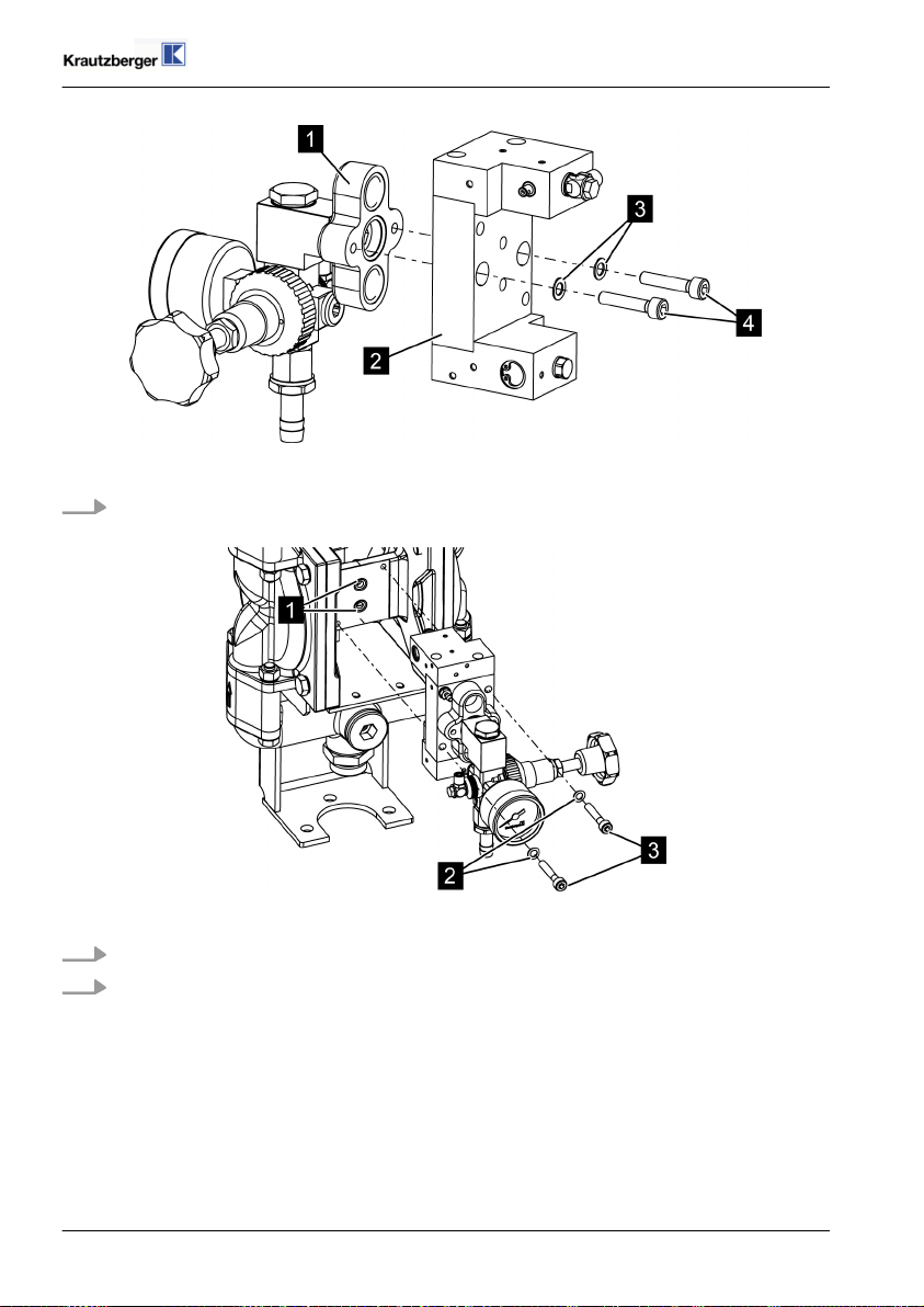
Fig. 10: Pressure controller
5. Unscrew the screws (Fig. 10/1).
6. Remove the complete unit from the pump with the pressure controller (Fig. 10/2).
mail@krautzberger.com, www.krautzberger.com GB–22

Diaphragm pump MP-520
Fig. 11: Pressure controller
7. Unscrew the screws (Fig. 11/1).
ENGLISH
Fig. 12: Pressure controller
8. Unscrew the fastening nipple (Fig. 12/7).
9. Replace the seals (Fig. 12/2, 5 and 6).
10. Remove the sound absorber (Fig. 12/4) from the valve adapter (Fig. 12/3) hand check for
wear. Replace it as necessary.
11. Screw the new pressure controller (Fig. 12/1) in place with the fastening nipple (Fig. 12/7)
as shown.
Article No. ■ 200-0216 ■ 200-0330
GB–23
Operating instructions
T-Dok-397-EN-Rev.0-
Fig. 13: Control valve
12. Screw the control valve (Fig. 13/2) to the valve adapter (Fig. 13/1) with the screws
(Fig. 13/4) and locking washers (Fig. 13/3).
web
Fig. 14: Pump
13. Replace the seals (Fig. 14/1).
14. Insert the complete unit into the pump and screw it to the pump with the screws (Fig. 14/3)
and the locking washers (Fig. 14/2)
mail@krautzberger.com, www.krautzberger.com GB–24

Diaphragm pump MP-520
ENGLISH
Fig. 15: Panelling
15. Put on the panelling (Fig. 15/2) and fasten it in place with the screws (Fig. 15/1).
Article No. ■ 200-0216 ■ 200-0330
GB–25

Operating instructions
8 Spare parts/accessories
8.1 Diaphragm pump spare parts
T-Dok-397-EN-Rev.0-
web
Fig. 16: Diaphragm pump spare parts
mail@krautzberger.com, www.krautzberger.com GB–26

Diaphragm pump MP-520
ENGLISH
Fig. 17: Diaphragm pump spare parts
Article No. ■ 200-0216 ■ 200-0330
GB–27

Operating instructions
Diaphragm pump spare parts list
T-Dok-397-EN-Rev.0-
web
8.2 Accessories
There are a wide range of accessories available for the diaphragm pumps. For further information,
visit us on the Internet (www.krautzberger.com) or contact your Krautzberger specialist dealer,
consultant or our office staff. Here are a few examples:
n Surge tank with removable cleaning cover and pressure gauge for balancing out the pulsation
and displaying the set material pressure.
n Several suction devices in various models, with sieve basket.
n Pressure pipe with pressure gauge for displaying the set material pressure.
n Material filter with drain valve.
n Material pressure controller for absolutely constant material pressure, ever in very low pres-
sure ranges.
n Pneumatic pump stroke devices.
n Carriage with pump stand.
n Wall brackets.
n Container lids for diaphragm pump build-up.
n Material drain valve.
n ... and additional accessories.
mail@krautzberger.com, www.krautzberger.com GB–28

Diaphragm pump MP-520
9 EU declaration of conformity
ENGLISH
Article No. ■ 200-0216 ■ 200-0330
GB–29

Operating instructions
T-Dok-397-EN-Rev.0-
web
mail@krautzberger.com, www.krautzberger.com GB–30

Diaphragm pump MP-520
ENGLISH
Article No. ■ 200-0216 ■ 200-0330
GB–31


Krautzberger GmbH
Stockbornerstraße 13
65343 Eltville am Rhein, Germany
Hotline: +49 (0) 6123 698-222
Reception: +49 (0) 6123 698-0
Fax: +49 (0) 6123 698-200
email: mail@krautzberger.com
Internet: www.krautzberger.com
© Krautzberger GmbH 2011
 Loading...