

GB
Operating instructions
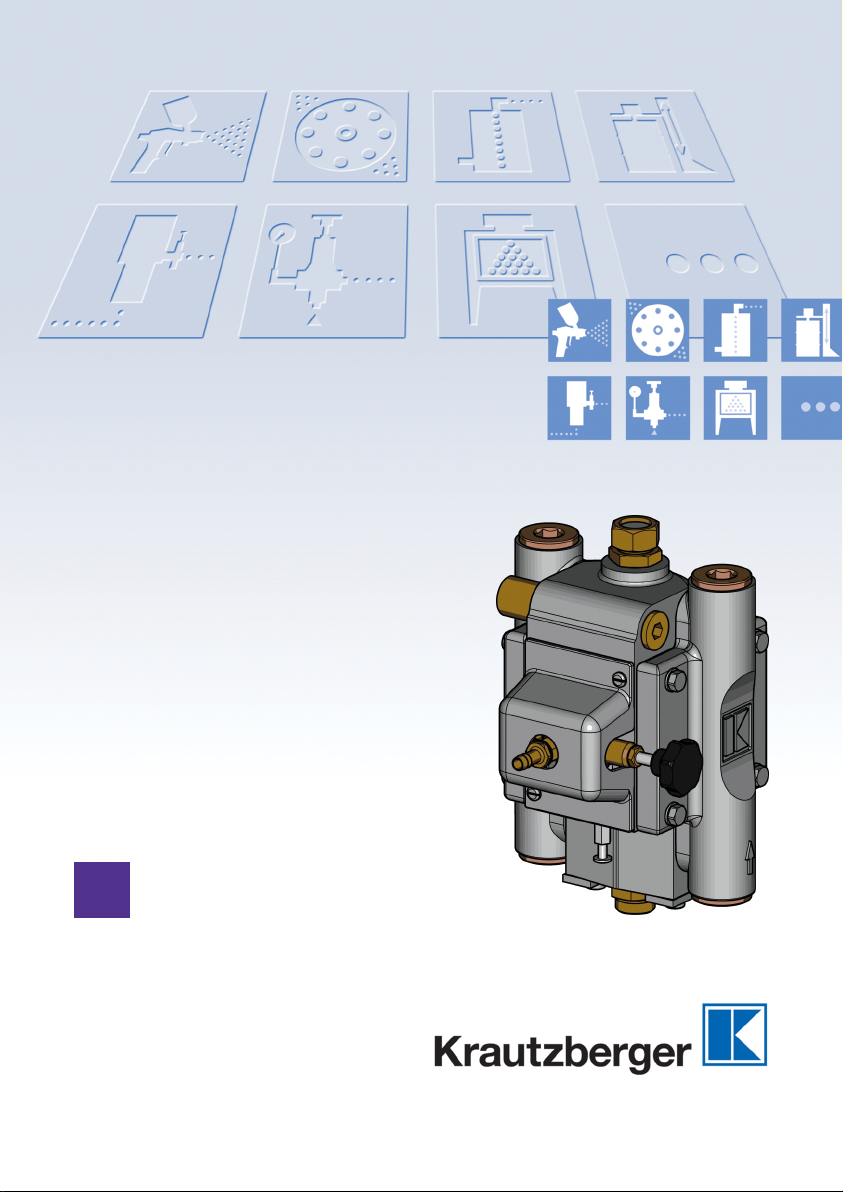
Diaphragm pump MP-400
T-Dok-236-GB-Rev.3
Item number: 200-0102
Translation of the original operating instructions

Thank you for selecting a Krautzberger product.
This product has been manufactured following state-of-the-art manufacturing procedures and
extensive quality assurance measures. We promise you a product of the highest quality.
If you have questions, requests or suggestions, please contact us. We are always glad to assist
you.
Information about the operating manual
This manual provides important information on how to work with the device safely and efficiently.
The manual is part of the device and must always be kept in the immediate proximity of the device
so that it is accessible to the personnel at all times.
The personnel must have read and understood this manual before starting any work. Compliance
with all specified safety information and instructions is a basic requirement for safe working conditions.
In addition, the local occupational safety regulations and general safety rules apply for the area of
application of the device.
Due to optional finishing variants, it is possible that the figures shown in this operating manual
deviate from your device.
Information about explosion protection
Many of our competitors have been marking their products with the Ex symbol as a matter of principle for some time now.
At Krautzberger we do not do that.
We engineer and manufacture our products in line with currently applicable directives.
If the labelling on the product is required, it is affixed to the product as the result of the necessary
analysis of ignition sources. If no labelling is affixed, the analysis of ignition sources and previous
experience with the assessment of the suitability of products for use in a potentially explosive area
have shown that the product described in this operating manual does not represent a potential
source of ignition, with the exception of an electrostatic charge.
Taking into account the potential equalisation (provided by proper earth connection), the use in an
area at risk for explosions is permitted in accordance with the currently valid directives.
GB–2
mail@krautzberger.com, www.krautzberger.com

Diaphragm pump MP-400
ENGLISH
Table of contents
1 Function and identification................................................................................................ 5
1.1 Function....................................................................................................................... 5
1.2 Identification................................................................................................................. 5
2 Using this operating manual............................................................................................. 6
2.1 Information about the operating manual...................................................................... 6
2.2 Symbols in this operating manual................................................................................ 6
2.3 Personnel requirements............................................................................................... 8
2.4 Personal protective equipment.................................................................................... 8
3 Safety and responsibility................................................................................................. 11
3.1 Responsibility of the owner........................................................................................ 11
3.2 Intended use.............................................................................................................. 11
3.3 Predictable misuse.................................................................................................... 11
3.4 General safety instructions........................................................................................ 12
3.5 Residual risks............................................................................................................ 13
3.6 Course of action in an emergency............................................................................. 14
4 Transport, storage, and packaging................................................................................. 15
4.1 Transport................................................................................................................... 15
4.2 Storage...................................................................................................................... 15
4.3 Packaging.................................................................................................................. 15
5 Menu.................................................................................................................................. 16
6 Installation......................................................................................................................... 17
6.1 Safety......................................................................................................................... 17
6.2 General installation information................................................................................. 18
6.3 Installing the diaphragm pump................................................................................... 19
6.4 Connecting the diaphragm pump............................................................................... 21
7 Operation........................................................................................................................... 23
7.1 Safety......................................................................................................................... 23
7.2 General information about the start-up...................................................................... 25
7.3 Shut-down.................................................................................................................. 25
7.3.1 Temporary shut-down............................................................................................. 25
7.3.2 Long-term shut-down.............................................................................................. 25
7.4 Start-up...................................................................................................................... 26
8 Maintenance...................................................................................................................... 27
8.1 Safety......................................................................................................................... 27
8.2 General maintenance information.............................................................................. 28
8.3 Maintenance schedule............................................................................................... 28
8.4 Clean the diaphragm pump....................................................................................... 29
Item number: 200-0102
GB–3

Operating instructions
T-Dok-236-GB-Rev.3
8.5 Replace valve parts................................................................................................... 30
8.6 Replace the diaphragm.............................................................................................. 32
9 Faults................................................................................................................................. 34
9.1 Safety......................................................................................................................... 34
9.2 Customer Care.......................................................................................................... 34
9.3 Fault table.................................................................................................................. 35
9.4 Fault rectification work............................................................................................... 36
9.4.1 Moving the control piston into the end position....................................................... 36
9.5 Replacing the pressure controller.............................................................................. 37
10 Spare parts........................................................................................................................ 40
11 Accessories...................................................................................................................... 41
12 Disassembly and disposal............................................................................................... 42
12.1 Safety....................................................................................................................... 42
12.2 Disassembly............................................................................................................ 42
12.2.1 Dismantling the diaphragm pump......................................................................... 43
12.3 Disposal................................................................................................................... 45
13 Technical data................................................................................................................... 46
13.1 Dimensions.............................................................................................................. 47
14 Declaration of conformity................................................................................................ 48
15 Notes.................................................................................................................................. 49
16 Index.................................................................................................................................. 50
mail@krautzberger.com, www.krautzberger.com GB–4
Diaphragm pump MP-400
ENGLISH
1 Function and identification
1.1 Function
The MP-400 is an air-operated diaphragm pump.
By changing the pressure in the air supply, the conveying capacity of the diaphragm pump can be
seamlessly regulated.
As soon as the set fluid pressure has been reached, the diaphragm pump switches off automatically. The fluid pressure is maintained until material is extracted at the extraction point. The diaphragm pump switches on automatically and keeps the set fluid pressure constant.
It is optimally suited for conveying paints, oils, etc.
1.2 Identification
Scope of delivery Model Product number
Diaphragm pump MP-400 200-0102
Operating instructions T-Dok-236
Serial number
Fig. 1: Serial number
The serial number ( Fig. 1) of the diaphragm pump is located on the underside. It serves as a
unique identifier.
Item number: 200-0102
GB–5
Operating instructions
T-Dok-236-GB-Rev.3
2 Using this operating manual
2.1 Information about the operating manual
n Knowledge of the fundamental safety instructions and safety regulations is a basic require-
ment for safe handling and defect-free operation of the product.
n This operating manual contains the most important information about enabling safe operation
of the product.
n This operating manual and, in particular, the safety instructions are to be observed by all per-
sons who work on or with the product.
n Furthermore, the rules and regulations for accident prevention in force at the respective oper-
ating site are to be observed.
2.2 Symbols in this operating manual
Safety instructions
This operating manual uses symbols to identify safety instructions. The safety instructions are preceded by signal words that indicate the severity of the hazard.
DANGER!
This combination of symbol and signal word indicates an immediate dangerous situation,
which will cause death or severe injuries if it is not averted.
WARNING!
This combination of symbol and signal word indicates a potentially dangerous situation which
can cause death or severe injuries if it is not averted.
CAUTION!
This combination of symbol and signal word indicates a potentially dangerous situation which
can cause slight injuries if it is not averted.
NOTICE!
This combination of symbol and signal word indicates a potentially dangerous situation which
can cause property and environmental damage if it is not averted.
mail@krautzberger.com, www.krautzberger.com GB–6
Diaphragm pump MP-400
ENGLISH
ENVIRONMENT!
This combination of symbol and signal word indicates potential dangers to the environment.
Tips and recommendations
This symbol highlights useful tips and recommendations as well as information for efficient
and defect-free operation.
Example for safety instructions in operating instructions
Safety instructions can refer to specific, individual operating instructions. Such safety instructions
are embedded in the operating instructions so that they do not disrupt the reading flow when performing the action. The signal words described above are used.
1. Loosen the screw.
2.
CAUTION!
Pinching hazard at the lid!
Carefully close the lid.
3. Tighten the screw.
Special safety instructions
The following symbols are used in safety instructions to draw attention to specific hazards:
Warning signs Type of danger
Warning – hot surface.
Warning – danger zone.
Additional markings
The following markings are used in this manual to highlight operating instructions, outcomes, lists,
references, and other elements:
Item number: 200-0102
GB–7

Operating instructions
T-Dok-236-GB-Rev.3
Identification Explanation
Step-by-step instructions
ð
Results of procedural steps
References to sections in this manual and other applicable documents
Lists without specified order
[Button] Operating elements (e.g. buttons, switches), display elements
(e.g. signal lights)
‘Display’ Screen elements (e.g. pushbuttons, assignment of function keys)
2.3 Personnel requirements
This manual identifies the qualifications of the personnel for the different scopes of work as listed
below:
Qualified personnel
Due to their specialised professional training, knowledge, and experience as well as knowledge of
the industry-specific standards and regulations, qualified personnel are in a position to perform
assigned tasks and to identify and avert potential risks on their own.
Specialised personnel
Due to their specialised professional training, knowledge, and experience as well as knowledge of
the industry-specific standards and regulations, qualified personnel are in a position to perform
assigned tasks and to identify and avert potential hazards on their own.
Trained electrician
Due to specialised professional training, knowledge and experience as well as knowledge of the
industry specific standards and regulations, a trained electrician is able to carry out work on the
electrical systems and to identified and avert potential risks on his/her own.
The trained electrician has completed specialised training for the specific work environment where
he/she works and knows the relevant standards and regulations.
User
The user is familiar with the basic regulations on occupational safety and accident prevention.
2.4 Personal protective equipment
Personal protective equipment is used to protect persons against adverse effects on their health
and safety when working.
Personnel must wear personal protective equipment while carrying out the different tasks on and
with the machine.
In the course of regular, recurring trainings, the owner should inform operating personnel that
working without protective equipment can be detrimental to their health.
mail@krautzberger.com, www.krautzberger.com GB–8

Diaphragm pump MP-400
ENGLISH
Protective equipment is selected according to the ambient conditions at the owner’s premises
and the raw materials that are used. The information provided by the material manufacturer
on the safety data sheet must be adhered to in order to ensure the proper selection of protective equipment.
The recommended personal protective equipment is described below:
Light respiratory protection
Light respiratory protection is used as protection against hazardous dusts.
Protective gloves
Protective gloves protect hands from friction, abrasion, puncture wounds, or deeper injuries, as
well as from contact with hot surfaces.
Safety goggles
Safety goggles are used to protect the eyes from airborne components and splashes of liquid.
Item number: 200-0102
GB–9

Operating instructions
T-Dok-236-GB-Rev.3
Protective clothing
Protective clothing are tight fitting work clothes with low tear resistance, with tight sleeves, and
without any protruding parts.
Safety shoes
Safety shoes protect the feet against crushing, falling parts or slipping on slippery ground.
Safety helmet
The helmet protects the head from falling parts and oscillating loads on the one hand, and it can
protect it from injuries in cramped situations on the other.
mail@krautzberger.com, www.krautzberger.com GB–10

Diaphragm pump MP-400
ENGLISH
3 Safety and responsibility
3.1 Responsibility of the owner
Owner
The owner is the person, who directly operates the machine for commercial or economical purposes or who allows a third-party to use/apply it and who is responsible for the legal product stewardship for the protection of the user, the personnel or third parties.
Owner responsibilities
The machine is used in an industrial environment. The owner of the machine is therefore subject to
the obligations as stipulated by the Occupational Health and Safety Act.
In addition to the safety information in this manual, the country-specific safety, accident prevention
guidelines and environmental protection regulations, applicable at the site of implementation of the
machine must be adhered to.
Furthermore, the owner is responsible for making sure that the machine is always in perfect technical condition. Therefore, the following applies:
n The owner must ensure that the maintenance intervals described in this operating manual are
adhered to.
n The owner must have all safety equipment checked regularly for functionality and complete-
ness.
3.2 Intended use
The MP-400 diaphragm pump is a pump operated with compressed air and is used exclusively:
n for conveying liquid and low-viscosity coating material from depressurised storage con-
tainers.
n for supplying material to automatic spray guns, metering devices and such like.
The intended use also includes compliance with all of the specifications in this operating manual.
3.3 Predictable misuse
Any use beyond the intended use or any other use constitutes misuse.
n Always carry out installation, commissioning, and use in accordance with the steps described
in this operating manual.
n Ensure that the hose lines used meet the requirements with regard to pressure, chemical, and
mechanical loads.
n Always observe the applicable country-specific safety, accident prevention, occupational
safety, and environmental protection regulations etc. for the area of use for the diaphragm
pump.
n The chemical resistance of the materials which we use cannot always be assessed with
authority due to the large number of fluids used, concentrations, temperatures and impurities.
For this reason, please check the suitability as we cannot offer any guarantees in this regard.
n Adhere to the safety data sheets of the spray medium manufacturer.
n Only use the manufacturer's OEM parts.
n Only operate the diaphragm pump in compliance with the values specified in (
‘Technical data’ on page 46).
n Only operate the diaphragm pump after fastening it properly to a suitable supporting structure.
n Do not hold the diaphragm pump in your hand during operation.
Item number: 200-0102
Ä
Chapter 13
GB–11

Operating instructions
T-Dok-236-GB-Rev.3
n Make sure that the connected compressed air is oil-free and free from solid matter.
n Operate the diaphragm pump with processed, dried compressed air (air quality pursuant to
DIN ISO 8573-1: quality class 4).
n Never point the compressed air at living beings.
n It is imperative to adhere to maintenance and cleaning intervals.
n The conformity of the product is voided in case of structural modifications of the diaphragm
pump.
n Do not use the diaphragm pump in the food or pharmaceutical industries.
WARNING!
Improper use of the diaphragm pump can lead to hazardous situations.
No claims of any kind can be asserted due to damage resulting from misuse.
3.4 General safety instructions
WARNING!
Risk of death, risk of injury or property damage due to hazardous media!
Potential consequences: The application of hazardous media can lead to death, severe injuries or property damage.
When handling hazardous substances, ensure that the current safety data sheets of the hazardous substance manufacturer are available. The necessary measures can be derived from
the content of the safety data sheet. Since the hazardous potential of a material can be reassessed at any time due to new lessons learned, the safety data sheet must be checked regularly and replaced if necessary.
The system owner is responsible for the presence and the up-to-date status of the safety data
sheet and the associated generation of the risk assessment of the effected workstations.
WARNING!
Hazardous media / contamination of persons and equipment
Possible consequences: Fatality or serious injuries, property damage
– Ensure the resistance of the device against the medium that is to be conveyed
– Always adhere to the safety data sheet of the medium that is to be conveyed The system
owner is responsible that the safety data sheet is present and up-to-date
– The safety data sheet of the conveyed medium is always authoritative for the initiation of
countermeasures in case of a leak of the conveyed medium
– Adhere to the general limitations with respect to viscosity limits, chemical stability and
density
mail@krautzberger.com, www.krautzberger.com GB–12

Diaphragm pump MP-400
ENGLISH
WARNING!
Risk of injury due to hot surfaces!
The surfaces of components can become very hot during operation. Direct contact with hot
surfaces causes severe skin burns.
Note:
– Always wear protective clothing and protective gloves for all work in the vicinity of hot
parts.
– Ensure that all surfaces have sufficiently cooled down prior to starting any work.
CAUTION!
Risk of injury caused by compressed air!
Uncontrolled leaks of compressed air can lead to serious injuries.
Note:
– Prior to any work on the device/machine, all compressed-air lines must be closed and
disconnected.
– Never point compressed air at living beings.
Operation in indoor and outdoor areas!
During operation in indoor and outdoor areas, use suitable measures to protect the device
against ambient conditions such as:
– Moisture
– UV radiation
– Frost, etc.
3.5 Residual risks
Devices, machines or systems made by Krautzberger GmbH have been manufactured based on
state-of-the-art technology and in compliance with technical safety regulations.
Nonetheless, their use may pose a threat to the life or health of users or third parties, or harm the
device, the machine, the system or other material assets.
n Mechanical hazards (crushing, shearing, cutting, jamming, burning, etc.) are possible at any
time during the installation, during operation as well as during maintenance work and servicing.
Item number: 200-0102
GB–13

Operating instructions
T-Dok-236-GB-Rev.3
3.6 Course of action in an emergency
In principle, the applicable national, regional and internal company regulations concerning the
course of action in case of an emergency must be adhered to and if necessary respective
safety measures must be taken on the system owner's side.
mail@krautzberger.com, www.krautzberger.com GB–14

Diaphragm pump MP-400
ENGLISH
4 Transport, storage, and packaging
4.1 Transport
n The diaphragm pump is protected by cardboard packaging.
n The cardboard packaging can be reused for storage.
4.2 Storage
Store packaged units subject to following conditions:
n Do not store outside.
n Store in a dry and dust-free environment.
n Keep away from any aggressive media.
n Protect from UV radiation.
n Avoid mechanical shocks.
n Storage temperature: 15 to 40 °C.
n Relative atmospheric humidity: max. 60%.
4.3 Packaging
The diaphragm pump is packaged in accordance with the anticipated transport conditions and the
packaging needs to protect it against transport damage, corrosion, and other damage.
n Remove packaging material.
n Remove potentially present transport safety restraints.
Item number: 200-0102
GB–15
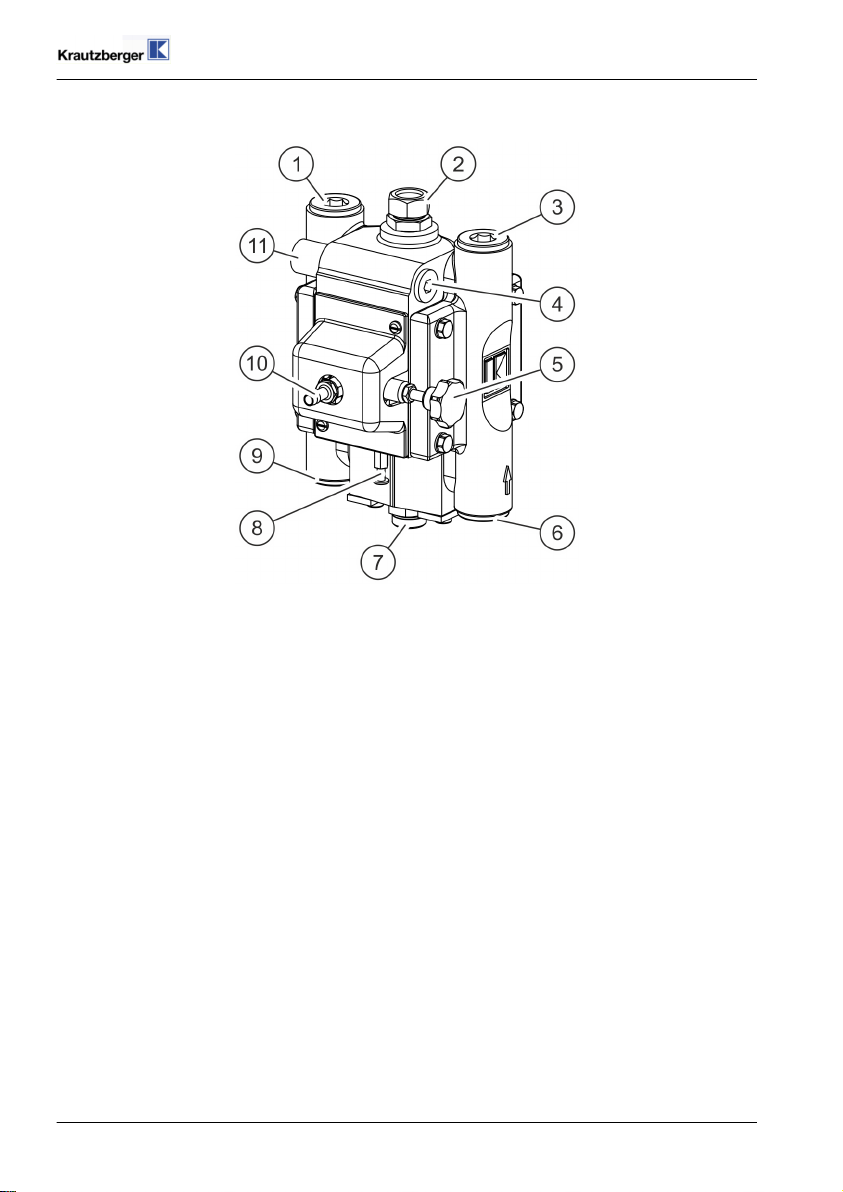
5 Menu
Fig. 2: Menu
1 Screw plug
2 Surge tank connection
3 Screw plug
4 Screw plug
5 Compressed air controller
6 Screw plug
7 Fluid intake connection (fluid inlet)
8 Auxiliary actuator
9 Screw plug
10 Compressed-air connection
11 Fluid pressure connection (fluid outlet)
Operating instructions
T-Dok-236-GB-Rev.3
mail@krautzberger.com, www.krautzberger.com GB–16

Diaphragm pump MP-400
ENGLISH
6 Installation
6.1 Safety
Personnel:
Specialised personnel
n
Trained electrician
n
Protective equipment:
The selection of the protective equipment depends on the installation conditions on site. Always
observe the applicable country-specific safety, accident prevention, occupational safety, and environmental protection regulations for the proper selection of the protective equipment.
WARNING!
Risk of injury due to improper installation!
Improper installation may cause serious personal injury or material damage.
Note:
– Ensure ample of space for the installation prior to starting any work.
– Carefully handle open, sharp-edged components.
– Maintain order and cleanliness at the installation site. Components that are loosely
stacked or are scattered around can cause accidents.
– Assemble components properly. Adhere to specified screw tightening torque.
– Secure components against tipping or falling.
– Ensure that the utilised hose lines meet the requirements for pressure, chemical and
mechanical loads. At the same time, adhere to the spray media manufacturer's specifica-
tions in the safety data sheet.
CAUTION!
Risk of injury through compressed air!
Uncontrolled leaks of compressed air can lead to serious injuries!
– Prior to any work on the device, all compressed-air lines must be closed and bleed if nec-
essary.
Item number: 200-0102
GB–17

Operating instructions
T-Dok-236-GB-Rev.3
CAUTION!
Risk of injury due to sharp edges!
Sharp edges and pointed corners can cause abrasions and cuts on the skin.
Note:
– Proceed cautiously when working on or near sharp edges and pointed corners.
– Wear protective gloves, if in doubt.
6.2 General installation information
Adhere to the following general information for the installation:
n Only carry out the installation and start-up in accordance with the steps described in these
operating instructions.
n Ensure that the utilised hose lines meet the requirements for pressure, chemical and mechan-
ical loads.
n Only operate the diaphragm pump after fastening it properly to a suitable supporting structure.
n Install the diaphragm pump vertically and with the fluid intake connection pointing down.
n Vibrations may occur on the diaphragm pump during operation. Ensure sufficient fastening.
n Make sure that the connected compressed air is oil-free and free of solid matter.
n Operate the diaphragm pump with processed, dried compressed air (air quality pursuant to
DIN ISO 8573-1: quality class 4).
n Never point the compressed air at living beings.
mail@krautzberger.com, www.krautzberger.com GB–18

Diaphragm pump MP-400
ENGLISH
6.3 Installing the diaphragm pump
Fig. 3: Installation
1. Attach the bracket ( Fig. 3/1) to a wall or supporting construction with the appropriate
screws so that the fluid intake connection ( Fig. 3/2) faces vertically downwards after
assembly.
Fig. 4: Installation
2. Lightly grease three screws ( Fig. 4/3).
3. Attach the diaphragm pump ( Fig. 4/4) to the bracket ( Fig. 4/2) with the screws ( Fig. 4/3).
4. Screw the earth connection to the earth connection screw ( Fig. 4/1).
Item number: 200-0102
GB–19

Operating instructions
WARNING!
Risk of fatal injury from electrostatic charge!
Electrostatic charges can cause shocks and sparks and thus lead to explosions.
– Ensure proper earth connection.
– Use conductive hose line (< 1 MW).
T-Dok-236-GB-Rev.3
mail@krautzberger.com, www.krautzberger.com GB–20

Diaphragm pump MP-400
6.4 Connecting the diaphragm pump
Connection scheme - Air and material supply
ENGLISH
Fig. 5: Connection example
1 Ball cock
2 Diaphragm pump MP-400
3 Surge tank
4 Screw connection
5 Material filter
6 Reducer
7 Material controller
8 Low-pressure fluid hose with fittings
9 Spray gun
10 Air controller unit with filter
11 Intake hose with suction cage
Item number: 200-0102
GB–21

Operating instructions
T-Dok-236-GB-Rev.3
Connection
Fig. 6: Connection
1. Connect the fluid intake hose to the fluid intake connection (fluid inlet) ( Fig. 6/3).
2. Connect the fluid pressure hose to the fluid pressure connection (fluid outlet) ( Fig. 6/4).
The fluid pressure connection can be made on the left or right.
3. If applicable, connect the surge tank to the connection ( Fig. 6/1).
4. Connect the compressed-air supply to the compressed-air connection point ( Fig. 6/2).
The compressed air supply must be dry, free of oil and secured by a pressure relief
valve.
Check all connections for a tight fit.
5.
mail@krautzberger.com, www.krautzberger.com GB–22

Diaphragm pump MP-400
ENGLISH
7 Operation
7.1 Safety
Personnel:
User
n
Specialised personnel
n
Protective equipment:
The selection of the personal protective equipment depends on the utilised medium of the system
owner. The information provided by the medium manufacturer indicated on the safety data sheet
must be adhered to in order to ensure the proper selection of personal protective equipment.
WARNING!
Risk of injury due to improper operation!
Improper operation can lead to serious personal injuries or property damage.
Note:
– Never point compressed air at people.
– Check the material and compressed air hose lines before each use for damage and tight
fit.
– Adhere to the spray media manufacturer's specifications in the safety data sheet.
– Make sure that the connected compressed air is oil-free and free of solid matter.
WARNING!
Risk of death, risk of injury or property damage due to hazardous media!
Potential consequences: The application of hazardous media can lead to death, severe injuries or property damage.
When handling hazardous substances, ensure that the current safety data sheets of the hazardous substance manufacturer are available. The necessary measures can be derived from
the content of the safety data sheet. Since the hazardous potential of a material can be reassessed at any time due to lessons learned, the safety data sheet must be checked regularly
and replaced if necessary.
The system owner is responsible for the presence and the up-to-date status of the safety data
sheet and the associated generation of the risk assessment of the effected workstations.
Item number: 200-0102
GB–23

Operating instructions
T-Dok-236-GB-Rev.3
WARNING!
Hazardous media / contamination of persons and equipment
Possible consequences: Fatality or serious injuries, property damage
– Ensure the resistance of the device against the medium that is to be conveyed
– Always adhere to the safety data sheet of the medium that is to be conveyed The system
owner is responsible that the safety data sheet is present and up-to-date
– The safety data sheet of the conveyed medium is always authoritative for the initiation of
countermeasures in case of a leak of the conveyed medium
– Adhere to the general limitations with respect to viscosity limits, chemical stability and
density
WARNING!
Risk of fatal injury, risk of injury or property damage due to damaged or disconnected
lines!
Damaged or disconnected lines can cause death, serious injuries or property damage due to
whip-like movements and the spraying of fluids.
Note:
– Check the fluid and compressed air lines for damage and a tight fit prior to every work
process.
WARNING!
Risk of injury due to hot surfaces!
The surfaces of components can become very hot during operation. Direct contact with hot
surfaces causes severe skin burns.
– Do no touch hot surfaces during operation, wear protective gloves if necessary.
– Ensure that all surfaces have sufficiently cooled down prior to starting any work.
mail@krautzberger.com, www.krautzberger.com GB–24

Diaphragm pump MP-400
WARNING!
Hearing damage due to excessive noise exposure!
Depending on the operating conditions, the sound pressure of the device/machine may cause
hearing damage.
Note:
– Take suitable action to reduce the impact of the existing sound pressure level. The owner
is responsible for the type and implementation of suitable measures, which may depend
on the local conditions.
ENGLISH
7.2 General information about the start-up
Adhere to the following general information for the start-up:
n Carry out the start-up of the diaphragm pump only in compliance to the steps described in this
operating manual.
n Always observe the applicable country-specific safety, accident prevention, occupational
safety, and environmental protection regulations for the area of use for the diaphragm pump.
n Check the material and compressed air hose lines for damage and tight fit before each use.
n The chemical consistency of the materials used by us cannot always be reliably assessed due
to the large variety of utilised fluids, concentrations, temperatures, and impurities. For this
reason, please test the suitability because we cannot extend any respective guarantees.
n Adhere to the spray media manufacturer's safety data sheets.
n Only operate the diaphragm pump in compliance with the values specified in (
‘Technical data’ on page 46).
n Only operate the diaphragm pump after fastening it properly to a suitable supporting structure.
n Do not hold the diaphragm pump in your hand during operation.
n It is recommended to flush the diaphragm pump prior to initial start-up using a suitable
cleaning agent.
n Make sure that the connected compressed air is oil-free and free of solid matter.
Ä
Chapter 13
7.3 Shut-down
7.3.1 Temporary shut-down
Interrupt the compressed air supply in a suitable location (e.g. shut-off device).
7.3.2 Long-term shut-down
1. Interrupt the compressed air supply in a suitable location (e.g. shut-off device).
2.
Clean diaphragm pump ( Ä Chapter 8.4 ‘Clean the diaphragm pump’ on page 29).
3. Interrupt the compressed air supply at a suitable location (e.g. shut-off device) and secure it
against a restart.
Item number: 200-0102
GB–25

Operating instructions
T-Dok-236-GB-Rev.3
7.4 Start-up
Adhere to the operating instructions for the respective components.
1. Check the material and compressed air lines to make sure they are undamaged and have a
secure fit.
2. Switch on compressed-air supply provided by the system owner.
3. Make sure that there is air pressure of 4 to 8 bar.
4. Make sure that the fluid intake hose is dipped into the material.
Fig. 7: Compressed air controller
5.
NOTICE!
Risk of increased wear in idle mode!
During initial commissioning there is still air in the diaphragm pump and the supply
lines. In idle mode the diaphragm pump is subject to particularly high levels of wear.
To bleed the pressure controller ( Fig. 7/1), first set a low air pressure.
6. Activate the extraction point (e.g. manual spray gun) until material escapes.
7. After successful bleeding, set the desired fluid pressure with the pressure controller.
mail@krautzberger.com, www.krautzberger.com GB–26

Diaphragm pump MP-400
ENGLISH
8 Maintenance
8.1 Safety
Personnel:
Specialised personnel
n
Protective equipment:
The selection of the protective equipment depends on the maintenance conditions on site and the
medium used by the owner. The applicable country-specific safety, accident prevention, occupational safety, and environmental protection regulations must be adhered to for the proper selection
of the protective equipment and the information given by the spray medium manufacturer on the
safety data sheet must be taken into consideration.
WARNING!
Risk of injury through the use of incorrect spare parts!
The use of incorrect or defective spare parts can cause hazards for the personnel as well as
damage, malfunctions or complete failure.
– Only use OEM parts from Krautzberger or Krautzberger-approved spare parts.
– In case of questions, always contact our Customer Care department.
WARNING!
Risk of injury due to a pressurised diaphragm pump!
Uncontrolled leaks of pressurised fluids or compressed air can cause serious injuries.
Therefore:
– Prior to any work on the diaphragm pump, all compressed air lines are to be closed and
secured against a restart.
– Never point compressed air at living beings.
– Activate the extraction point to depressurise the diaphragm pump.
CAUTION!
Risk of injury due to sharp edges!
Sharp edges and pointed corners can cause abrasions and cuts on the skin.
Note:
– Proceed cautiously when working on or near sharp edges and pointed corners.
– Wear protective gloves, if in doubt.
Item number: 200-0102
GB–27

Operating instructions
T-Dok-236-GB-Rev.3
Hose and pipelines
Even with intended use, the service life of hose and pipelines is limited due to environmental
influences. For the sake of prevention, all hose and pipelines should be replaced regularly
according to their load.
8.2 General maintenance information
The following sections describe the maintenance work that is required for optimal and fault-free
operation of the diaphragm pump.
Check wearing parts such as seals at regular intervals. The level of wear depends on the abrasiveness of the spray medium used. Escaping air and spray medium are signs that parts are worn.
Contact Krautzberger Customer Care should you have any questions about maintenance work and
maintenance intervals.
8.3 Maintenance schedule
Interval Maintenance work
Prior to each work process Check the material or compressed air lines to make sure they
Before performing any maintenance work
Prior to every long-term shutdown
When necessary
are undamaged and have a secure fit
Clean diaphragm pump ( Ä Chapter 8.4 ‘Clean the diaphragm
pump’ on page 29)
Clean diaphragm pump ( Ä Chapter 8.4 ‘Clean the diaphragm
pump’ on page 29)
Replace valve parts ( Ä Chapter 8.5 ‘Replace valve parts’
on page 30)
Replace diaphragm ( Ä Chapter 8.6 ‘Replace the diaphragm’
on page 32)
mail@krautzberger.com, www.krautzberger.com GB–28

Diaphragm pump MP-400
ENGLISH
8.4 Clean the diaphragm pump
WARNING!
Risk of injury due to improper cleaning!
Detergents may be harmful to one's health and be easily flammable. Furthermore, seals of the
diaphragm pump can be destroyed.
Note:
– Adhere to the safety data sheets of the cleaning product manufacturer.
– Do not fully immerse the diaphragm pump in a cleaning product.
– Do not use any high-pressure cleaning devices.
1. Interrupt the compressed air supply in a suitable location (e.g. shut-off device).
2. Dip the fluid intake hose into a suitable detergent.
3. Switch on the compressed air supply.
4. Rinse out the diaphragm pump by activating the extraction point until only detergent liquid
escapes.
5. Disrupt the compressed air supply and secure it against restart.
6. Activate the extraction point again to depressurize the diaphragm pump.
7. Leave detergent liquid in the diaphragm pump.
8. Clean the outside of the device with a cloth dipped in cleaning solution.
Item number: 200-0102
GB–29

Operating instructions
T-Dok-236-GB-Rev.3
8.5 Replace valve parts
1.
Clean diaphragm pump ( Ä Chapter 8.4 ‘Clean the diaphragm pump’ on page 29).
2. Make sure that the compressed air supply is switched off and secured against a restart.
3. Reduce the fluid pressure by activating the extraction point.
Fig. 8: Valve parts
4.
CAUTION!
Risk of injury from spring force!
The screw plugs are under pressure from springs.
Carefully unscrew each screw plug ( Fig. 8/1).
5. Remove the seal ( Fig. 8/2), valve spring ( Fig. 8/3), valve ball ( Fig. 8/4), valve seat (
Fig. 8/5), O-ring ( Fig. 8/6) and, if applicable, spacer basket ( Fig. 8/7).
6. Check all parts for damage and wear and replace them as necessary.
mail@krautzberger.com, www.krautzberger.com GB–30

Diaphragm pump MP-400
ENGLISH
WARNING!
Risk of injury due to improper cleaning!
Detergents may be harmful to one's health and be easily flammable. Furthermore, seals of the
diaphragm pump can be destroyed.
Note:
– Adhere to the safety data sheets of the cleaning product manufacturer.
– Do not fully immerse the valve housing in cleaning product.
– Do not use any high-pressure cleaning devices.
7. Clean the outside of the valve housing with a cloth soaked in cleaning product.
8. Install the O-ring ( Fig. 8/6), valve seat ( Fig. 8/5), valve ball ( Fig. 8/4), valve spring (
Fig. 8/3), seal ( Fig. 8/2) and, if applicable, spacer basket ( Fig. 8/7) in the order shown.
9. Tighten lock screw ( Fig. 8/1) (Tightening torque: 90 Nm).
10.
Clean the diaphragm pump ( Ä Chapter 8.4 ‘Clean the diaphragm pump’ on page 29) and
perform a test run (
Ä
Chapter 7.4 ‘Start-up’ on page 26).
Item number: 200-0102
GB–31

Operating instructions
T-Dok-236-GB-Rev.3
8.6 Replace the diaphragm
The following is a description of how to replace diaphragm using the example of the left-hand
side of the diaphragm pump.
1.
Clean diaphragm pump (
2. Make sure that the compressed air supply is switched off and secured against a restart.
3. Reduce the fluid pressure by activating the extraction point.
Ä
Chapter 8.4 ‘Clean the diaphragm pump’ on page 29).
Fig. 9: Unscrew the cover
4. Unfasten all 4 screw ( Fig. 9/1) and remove the cover ( Fig. 9/2).
Fig. 10: Unscrewing the diaphragm
5. Unscrew the diaphragm ( Fig. 10/3) from the control pin ( Fig. 10/2).
mail@krautzberger.com, www.krautzberger.com GB–32

Diaphragm pump MP-400
ENGLISH
WARNING!
Risk of injury due to improper cleaning!
Detergents may be harmful to one's health and be easily flammable. Furthermore, seals of the
diaphragm pump can be destroyed.
Note:
– Adhere to the safety data sheets of the cleaning product manufacturer.
– Do not use any high-pressure cleaning devices.
6. Clean contact surfaces of the cover.
7. Replace the O-rings ( Fig. 10/1).
8. Screw new diaphragm ( Fig. 10/3) firmly onto the control pin ( Fig. 10/2).
Fig. 11: Screwing the cover in place
9. Put on the cover ( Fig. 11/1), with the arrow ( Fig. 11/3) pointing upwards.
10. Lightly grease all 4 screws ( Fig. 11/2) and screw tight (Tightening torque: 20 Nm).
11.
Perform test run (
Item number: 200-0102
Ä
Chapter 7.4 ‘Start-up’ on page 26).
GB–33

Operating instructions
T-Dok-236-GB-Rev.3
9 Faults
9.1 Safety
Personnel:
Qualified personnel
n
Protective equipment:
The selection of the protective equipment depends on the medium used by the owner. The information provided by the medium manufacturer indicated on the safety data sheet must be adhered
to in order to ensure the proper selection of protective equipment.
How to act in case of dangerous faults
In principle, the following applies:
1. In the event of faults that pose an immediate risk to persons or material assets, switch off
the diaphragm pump immediately.
2. Determine the cause of the fault.
3. Inform the person responsible at the operating site about the fault.
4. In the event that troubleshooting requires work in the hazard area, switch off the diaphragm
pump and secure it against a restart.
5. Depending on the type of fault, eliminate the fault or have it eliminated by an authorised
specialist.
If the fault is not included in the following table or if it cannot be eliminated with the
measures described, contact Customer Care at Krautzberger GmbH.
9.2 Customer Care
Krautzberger GmbH
Customer service
Stockbornstr. 13
65343 Eltville am Rhein
+49 6123 698151
customercare@krautzberger.com
mail@krautzberger.com, www.krautzberger.com GB–34

Diaphragm pump MP-400
9.3 Fault table
Error Cause Remedy
Air bubbles in the material container
Diaphragm pump runs
unevenly
The diaphragm pump does not
start up
Diaphragm pump works but
there is no pressure build-up or
suction
Pressure fluctuations during
operation or unusual running
noises
Intake line loose/leaking Check the intake line, tighten if
necessary
Defective seal
Replace the seal ( Ä Chapter
8.5 ‘Replace valve parts’
on page 30)
Defective diaphragm Replace the diaphragm (
Ä
Chapter 8.6 ‘Replace the
diaphragm’ on page 32)
Foreign bodies in the ball valve
or worn valve
Check the ball valve, replace if
necessary
Air is sucked in Check the suction device
Intake line blocked Check the intake line, clean if
necessary
Valve balls/valve seat soiled/
leaking
Clean/replace the valve balls/
valve seat ( Ä Chapter 8.5
‘Replace valve parts’
on page 30)
No compressed air available Switch on or check the com-
pressed air supply
Control piston not in end position
Move the control piston to the
end position ( Ä Chapter 9.4.1
‘Moving the control piston into
the end position’ on page 36)
Defective pressure regulator Replace the pressure regulator
( Ä Chapter 9.5 ‘Replacing the
pressure controller’
on page 37)
Intake screen soiled Clean the intake screen
Suction hose is kinked Check the suction hose
Valve ball/valve seat soiled Clean the valve balls/valve
seat ( Ä Chapter 8.5 ‘Replace
valve parts’ on page 30)
Valve blocked Clean the valve, rinse the dia-
phragm pump
Valve ball/valve seat worn Replace the valve balls/valve
seat ( Ä Chapter 8.5 ‘Replace
valve parts’ on page 30)
Defective O-ring Replace the O-ring (
Ä
Chapter 8.5 ‘Replace valve
parts’ on page 30)
Diaphragm worn Replace the diaphragm (
Ä
Chapter 8.6 ‘Replace the
diaphragm’ on page 32)
ENGLISH
Item number: 200-0102
GB–35

Operating instructions
9.4 Fault rectification work
9.4.1 Moving the control piston into the end position
1. Make sure that the compressed air supply is switched off.
2. Reduce the fluid pressure by activating the extraction point.
Fig. 12: Auxiliary actuator
3.
NOTICE!
If the auxiliary control is actuated in a pressurised state, there is a risk of
destroying the valve!
T-Dok-236-GB-Rev.3
Press in the auxiliary control ( Fig. 12/1).
The control piston is pushed into the end position.
ð
4.
Perform test run ( Ä Chapter 7.4 ‘Start-up’ on page 26).
mail@krautzberger.com, www.krautzberger.com GB–36

Diaphragm pump MP-400
ENGLISH
9.5 Replacing the pressure controller
Disassembly
1. Make sure that the compressed air supply is switched off and secured against a restart.
2. Reduce the fluid pressure by activating the extraction point.
3. Disconnect the compressed air hose from the diaphragm pump.
Fig. 13: Cover hood
4. Unscrew the screws ( Fig. 13/1) and remove the cover hood ( Fig. 13/2).
Fig. 14: Pressure controller
5. Unscrew the screws ( Fig. 14/3) and remove locking washers ( Fig. 14/4).
6. Remove the complete unit from the pump with the pressure controller ( Fig. 14/2).
7. Replace the seals ( Fig. 14/1).
Item number: 200-0102
GB–37

Operating instructions
T-Dok-236-GB-Rev.3
Fig. 15: Pressure controller
8. Unscrew the screws ( Fig. 15/2) and remove with locking washers ( Fig. 15/3).
9. Remove valve adapter ( Fig. 15/4) from the housing ( Fig. 15/1).
Fig. 16: Pressure controller
10. Unscrew the fastening nipple ( Fig. 16/7).
11. Replace the seals ( Fig. 16/2, 5 and 6).
12. Remove the sound absorber ( Fig. 16/4) from the valve adapter ( Fig. 16/3) and check for
wear. Replace it as necessary.
Installation
13. Screw the new pressure controller in place with the fastening nipple.
14. Screw the housing to the valve adapter with the screws and locking washers.
mail@krautzberger.com, www.krautzberger.com GB–38

Diaphragm pump MP-400
ENGLISH
15. Insert the complete unit into the pump and screw it to the pump with the screws and the
locking washers.
16. Lightly grease screws of the cover hood.
17. Put on the cover hood and fasten it in place with the screws.
Item number: 200-0102
GB–39

Operating instructions
10 Spare parts
– Only use OEM parts from Krautzberger or Krautzberger-approved spare parts.
– In case of questions, always contact our Customer Care department.
Spare parts order – General
To make spare part ordering easier, please provide the following information:
– Serial number
– Model / product name
– Designation
– Item number according to spare parts list
– Quantity
– Desired shipping method (post, freight, sea, air, express)
– Delivery address
T-Dok-236-GB-Rev.3
A complete spare part overview is available on the website of Krautzberger GmbH:
www.krautzberger.de
mail@krautzberger.com, www.krautzberger.com GB–40

Diaphragm pump MP-400
ENGLISH
11 Accessories
There are a wide range of accessories available for the diaphragm pumps. For further information,
visit us on the Internet (www.krautzberger.com) or contact your Krautzberger specialist dealer,
consultant or our office staff. Here are a few examples:
n Pressure compensation tank with removable cleaning cover and pressure gauge for balancing
out the pulsation and displaying the set material pressure
n Suction devices in various designs, with filter basket
n Pressure pipe with pressure gauge for displaying the set material pressure
n Material filter with drain valve
n Material pressure controller for absolutely constant material pressure, even in very low pres-
sure ranges
n Pneumatic pump stroke devices
n Carriage with depositing surface
n Wall bracket
n Stand to hold wall console
n Container lids for diaphragm pump build-up
n Mount for lid installation
n Material drain valve
n ... and other accessories
Item number: 200-0102
GB–41

Operating instructions
T-Dok-236-GB-Rev.3
12 Disassembly and disposal
12.1 Safety
Personnel:
Qualified personnel
n
Protective equipment:
The selection of the protective equipment depends on the installation conditions on site and the
medium used by the owner. The applicable country-specific safety, accident prevention, occupational safety, and environmental protection regulations must be adhered to for the proper selection
of the protective equipment and the information given by the spray medium manufacturer on the
safety data sheet must be taken into consideration.
WARNING!
Risk of injury due to improper disassembly!
Residual stored energies, component edges, points and corners on or in the device or on the
required tools may cause injuries.
– Make sure you have sufficient space before starting the work.
– Carefully handle open, sharp edged components.
– Keep the workplace orderly and clean! Loosely stacked or scattered components and
tools are sources for accidents.
– Properly dismantle components. Pay attention to very high individual weight of some of
the components. If necessary, use hoisting equipment.
– Secure components so that they cannot fall or tip over.
– If questions arise, consult with the customer service from Krautzberger.
12.2 Disassembly
Prior to starting disassembly:
n Switch off the device and secure it against a restart.
n Physically disconnect the entire power supply from the device, and discharge any energy
stored in the machine.
n Remove and dispose of operating and auxiliary material as well as remaining processing
materials in an environmentally friendly manner.
Afterwards, properly clean components and modules and take them apart in compliance with applicable local occupational health & safety regulations as well as environmental protection regulations.
mail@krautzberger.com, www.krautzberger.com GB–42

Diaphragm pump MP-400
ENGLISH
12.2.1 Dismantling the diaphragm pump
WARNING!
Risk of injury through a pressurized diaphragm pump!
Uncontrollably leaking pressurized fluids or compressed air can cause serious injuries.
Note:
– Prior to any work on the device, all compressed-air lines must be closed and secured
against a restart.
– Never point compressed air at living beings.
– Activate the extraction point to depressurize the diaphragm pump.
Item number: 200-0102
GB–43

Operating instructions
1.
Clean diaphragm pump ( Ä Chapter 8.4 ‘Clean the diaphragm pump’ on page 29).
T-Dok-236-GB-Rev.3
2. Make sure that the compressed air supply is switched off and secured against a restart.
3. Reduce the fluid pressure by activating the extraction point.
Fig. 17: Connection
4. Disconnect the compressed-air supply from the compressed-air connection point (
Fig. 17/2).
5. Disconnect the fluid intake hose from the fluid intake connection (fluid inlet) ( Fig. 17/3).
6. Disconnect the fluid pressure hose from the fluid pressure connection (fluid outlet) (
Fig. 17/4).
7. If applicable, disconnect the surge tank at the connection ( Fig. 17/1).
Fig. 18: Installation
8. Disconnect the earth connection from the earth connection screw ( Fig. 18/1).
mail@krautzberger.com, www.krautzberger.com GB–44

Diaphragm pump MP-400
ENGLISH
9. Unscrew three screws ( Fig. 18/3) from the bracket ( Fig. 18/2) and the diaphragm pump (
Fig. 18/4).
12.3 Disposal
ENVIRONMENT!
Danger to the environment due to incorrect disposal!
Incorrect disposal may cause dangers to the environment.
If no return or disposal agreement has been made, recycle the dismantled parts:
n Scrap metals.
n Recycle plastic components.
n Sort remaining components based on the respective material and dispose of them accord-
ingly.
n Properly dispose of potential spray media residue separately from the device.
If in doubt, obtain information about environmentally-appropriate disposal from the local authorities
or specialised disposal companies.
Item number: 200-0102
GB–45

Operating instructions
T-Dok-236-GB-Rev.3
13 Technical data
Specification Value Unit
Delivery rate (with reference to water, free flow) 20 l/min
Material connection (outlet) G 1/2 internal thread Inch
Max. temperature of the coating material used 0 ... +50 °C
Maximum pressure performance 8 (116) bar (psi)
Max. permitted operating pressure 8 (116) bar (psi)
Compressed air connection (hose sleeve) 8 or 9 mm
Min. air intake pressure 4 (58) bar (psi)
Max. air intake pressure 8 (116) bar (psi)
Material pressure (depends on the material) approx. 0.5 to 8 (7.3 to 116) bar (psi)
Max. stroke (double strokes) 120 DS/min
Recommended number of strokes (double
strokes)
Weight 7.5 kg
Air consumption (at 8 bar) 160 l/min
Sound pressure level (at 8 bar and 100 DS) 78 dB(A)
Transmission ratio 1:1
Compressed air supply oil-free, filtered
100 DS/min
mail@krautzberger.com, www.krautzberger.com GB–46

Diaphragm pump MP-400
13.1 Dimensions
Fig. 19: Dimensions
ENGLISH
Item number: 200-0102
GB–47

Operating instructions
14 Declaration of conformity
T-Dok-236-GB-Rev.3
Fig. 20: Declaration of conformity
mail@krautzberger.com, www.krautzberger.com GB–48

Diaphragm pump MP-400
ENGLISH
15 Notes
______________________________________________________________________________
______________________________________________________________________________
______________________________________________________________________________
______________________________________________________________________________
______________________________________________________________________________
______________________________________________________________________________
______________________________________________________________________________
______________________________________________________________________________
______________________________________________________________________________
______________________________________________________________________________
______________________________________________________________________________
______________________________________________________________________________
______________________________________________________________________________
______________________________________________________________________________
______________________________________________________________________________
______________________________________________________________________________
______________________________________________________________________________
______________________________________________________________________________
______________________________________________________________________________
______________________________________________________________________________
______________________________________________________________________________
______________________________________________________________________________
______________________________________________________________________________
______________________________________________________________________________
______________________________________________________________________________
______________________________________________________________________________
______________________________________________________________________________
______________________________________________________________________________
______________________________________________________________________________
______________________________________________________________________________
______________________________________________________________________________
______________________________________________________________________________
Item number: 200-0102
GB–49

Operating instructions
T-Dok-236-GB-Rev.3
16 Index
A
Air consumption .................................................46
Application ....................................................11
C
Cleaning ......................................................29
Connection scheme ...............................................21
Conveying capacity ...............................................46
Customer Care ..................................................34
Customer service ................................................34
D
Delivery ......................................................15
Dimension sheet .................................................47
Dimensions ....................................................47
Disassembly ...................................................42
Disposal ......................................................45
E
Error ........................................................34
F
Fault table .....................................................35
Faults messages .................................................34
Function .......................................................5
I
Incorrect use ...................................................11
M
Menu ........................................................16
Misuse .......................................................11
N
Noise emission ..................................................46
O
Owner .......................................................11
P
Personnel ......................................................8
Pictograms .....................................................6
Pressure specifications .............................................46
Product number ..................................................5
mail@krautzberger.com, www.krautzberger.com GB–50

Diaphragm pump MP-400
ENGLISH
R
Recycling .....................................................45
S
Safety information ................................................12
Scope of delivery .................................................5
Serial number ...................................................5
Service .......................................................34
Sound pressure level ..............................................46
Storage ......................................................15
Symbols .......................................................6
T
Temperature ...................................................46
U
User qualification .................................................8
W
Weight .......................................................46
Item number: 200-0102
GB–51


Krautzberger GmbH
Stockbornstrasse 13
D-65343 Eltville am Rhein, Germany
Hotline: +49 (0) 6123 698-222
Head Office: +49 (0) 6123 698-0
Fax: +49 (0) 6123 698-200
Email: mail@krautzberger.com
Internet: www.krautzberger.com
© Krautzberger GmbH 2019
© Krautzberger GmbH 2019
 Loading...