

Krautzberger MP-100 Operating Instructions Manual

GB
Operating instructions
Diaphragm pump MP-100
T-Dok-237-DE-Rev.0
■ Article No. 200-0104
Translation of the original operating instructions

Thank you for selecting a Krautzberger product.
This product has been manufactured according to the latest manufacturing procedures and with
extensive quality assurance measures. We promise you a product of the highest quality
If you have questions, desires or suggestions, please contact us; we are always glad to assist you.
Information about the topic of Ex protection
Many of our competitors have been identifying their products with the Ex symbol for a while now.
Krautzberger does not do this.
We construct and manufacture our products according the currently-valid guidelines.
If the marking on the product is required, then it is affixed on the product as the result of the necessary analysis of ignition sources. If no marking is affixed, then the required analysis of ignition
sources as well as previous experience with the assessment of the applicability of the products in
the Ex area showed that the product described in these operating instructions provides no potential
source of ignition with the exception of the electrostatic charge.
Taking into account the potential equalisation (due to proper earthing), use in the Ex area is admissible according to the currently-valid guidelines.
mail@krautzberger.com, www.krautzberger.com GB–2

Diaphragm pump MP-100
ENGLISH
Table of contents
1 Safety................................................................................................................................... 4
1.1 DESIGNATED USE..................................................................................................... 4
1.2 Personnel requirements............................................................................................... 5
1.3 Personal protective equipment.................................................................................... 5
1.4 Disposal....................................................................................................................... 6
2 Technical data..................................................................................................................... 7
2.1 Dimensions.................................................................................................................. 7
2.2 General specifications................................................................................................. 7
2.3 Fluid conveyance properties........................................................................................ 8
3 Structure and function....................................................................................................... 9
3.1 Overview...................................................................................................................... 9
3.2 FUNCTIONAL DESCRIPTION.................................................................................... 9
4 Mounting and connection................................................................................................ 10
4.1 Mounting the diaphragm pump.................................................................................. 10
4.2 Connection example.................................................................................................. 11
4.3 Connecting the diaphragm pump............................................................................... 12
5 Operation........................................................................................................................... 13
5.1 Commissioning.......................................................................................................... 13
5.2 Interrupting operation................................................................................................. 15
6 Maintenance...................................................................................................................... 16
6.1 Maintenance schedule............................................................................................... 16
6.2 Maintenance work...................................................................................................... 17
7 Faults................................................................................................................................. 24
8 Spare parts/accessories.................................................................................................. 25
8.1 Spare parts................................................................................................................ 25
8.2 Accessories............................................................................................................... 28
9 EU declaration of conformity.......................................................................................... 29
■ Article No. 200-0104
GB–3

Operating instructions
T-Dok-237-DE-Rev.0
1 Safety
Safety instructions
DANGER!
This combination of symbol and signal word indicates an immediately dangerous situation
which causes death or severe injuries if it is not avoided.
WARNING!
This combination of symbol and signal word indicates a possibly dangerous situation which
can cause death or severe injuries if it is not avoided.
CAUTION!
This combination of symbol and signal word indicates a possibly dangerous situation which
can cause slight injuries if it is not avoided.
NOTICE!
This combination of symbol and signal word indicates a possibly dangerous situation which
can cause property and environmental damage if it is not avoided.
This symbol highlights useful tips and recommendations as well as information for efficient
and fault-free operation.
Symbol Explanation
Indicates step-by-step instructions.
ð
Indicates a condition or an automatic sequence as the result of an action.
Indicates references to sections of these instructions and other applicable
documents.
Indicates enumerations and list entries without a specified sequence.
1.1 DESIGNATED USE
The diaphragm pump MP-100 is a pump operated with compressed air and is used exclusively
mail@krautzberger.com, www.krautzberger.com GB–4

Diaphragm pump MP-100
ENGLISH
n for the conveying of liquid and low-viscosity coatings from pressureless storage containers,
n for the supply of fluid to spray guns. automatic spray guns, metering devices and similar.
It is mainly used for painting and coating operations.
Designated use also includes observance of all details in these instructions.
Any use beyond the designated use or any other use counts as misuse.
WARNING!
Danger due to misuse!
Misuse of the diaphragm pump can cause dangerous situations.
– Always observe the valid safety, accident prevention, occupational safety and environ-
mental protection regulations valid for the area of application of the diaphragm pump.
– Only use sharply abrasive, chemically-aggressive, very hot or very cold spray fluids in
consultation with Krautzberger GmbH.
– Only use the manufacturer's original spare parts.
– Only operate the diaphragm pump while adhering the values specified in the
2 ‘Technical data’ on page 7.
Ä
Chapter
– Only operate the diaphragm pump after proper fastening on a suitable carrier construc-
tion.
– Do not hold the diaphragm pump in your hand during operation.
– Heed the spray fluid manufacturer's safety datasheets.
– Do not use the diaphragm pump in the food or pharmaceutical sectors.
Claims of any type due to damage based on misuse are excluded.
1.2 Personnel requirements
Ensure the use of the device by skilled employees! Only skilled employees can independently
detect and avoid possible dangers during use based on their professional training, experience and
knowledge of the relevant regulations.
1.3 Personal protective equipment
When using the device, always wear breathing, eye and ear protection!
Only wear approved protective gloves during cleaning work with solvents!
■ Article No. 200-0104
GB–5

Operating instructions
T-Dok-237-DE-Rev.0
1.4 Disposal
When the useful life of the device has been exhausted, dispose of it in commercial waste. In order
to prevent damage to the environment, dispose of any remains of spray fluid properly separately
from the device.
mail@krautzberger.com, www.krautzberger.com GB–6

Diaphragm pump MP-100
2 Technical data
2.1 Dimensions
Fig. 1: Dimensions
ENGLISH
2.2 General specifications
Data Value Unit
Pump capacity (with respect to water, free flow) 10 l/min
Fluid connection (outlet) G 1/2 interior thread Inches
Max. temperature of the coating material used 0 ... +50 °C
Max. pressure 6,5 (94,3) bar (psi)
Max. operating pressure 8 (116) bar (psi)
Compressed air connection (hose sleeve) 8/9 mm
Min. air intake pressure 4 (58) bar (psi)
Max. air intake pressure 8 (116) bar (psi)
Max. stroke (double strokes) 120 DS/min
Recommended number of strokes (double strokes) 100 DS/min
Weight 5,0 kg
■ Article No. 200-0104
GB–7
Operating instructions
T-Dok-237-DE-Rev.0
Data Value Unit
Air consumption (at 8 bar) 80 l/min
Transformation ratio 1:1
Compressed air supply oil-free, filtered
2.3 Fluid conveyance properties
Fluid Suitability
Paint (with solvent) good
Water-based paint, dispersions, wood preservatives good
Water good
Oils, heating oils, diesel fuel good
Emulsions, soap, detergents good
Alcohol, glazes, latex limited
Lime sludges limited
Cell and fibre materials unsuitable
Sludge, mash, pastes unsuitable
In case of doubt about suitability, inquire about materials not listed. In special cases we will
determine the suitability in an experiment.
mail@krautzberger.com, www.krautzberger.com GB–8

Diaphragm pump MP-100
3 Structure and function
3.1 Overview
Fig. 2: Overview
1 Cover hood
2 Surge tank connection
3 Fluid pressure connection
4 Fixing bracket
5 Fluid intake connection
6 Compressed air regulator
7 Compressed air connection
ENGLISH
3.2 FUNCTIONAL DESCRIPTION
The pressure desired at the extraction point can be adjusted steplessly using the compressed air
regulator (Fig. 2/6). As soon as the set fluid pressure has been reached, the diaphragm pump
switches off automatically. The fluid pressure is maintained until fluid is extracted at the extraction
point. The diaphragm pump switches on automatically and keeps the set fluid pressure constant.
■ Article No. 200-0104
GB–9
Operating instructions
4 Mounting and connection
4.1 Mounting the diaphragm pump
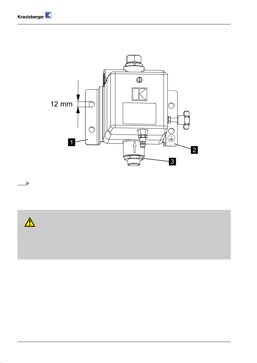
Fig. 3: Mounting
Mount the diaphragm pump vertically with the fixing brackets (Fig. 3/1 and 2) and suitable
fastening screws, with the fluid intake connection (Fig. 3/3) facing downward, on a wall or
supporting structure.
Screw onto the earthing with the fixing bracket (Fig. 3/2).
T-Dok-237-DE-Rev.0
WARNING!
Danger to life due to electrostatic charge!
Electrostatic charges can cause shocks and spark formation and thus explosions.
– Ensure proper earthing.
mail@krautzberger.com, www.krautzberger.com GB–10
 Loading...