

Krautzberger 200-0138, Magnon 3, 200-0187, 200-0137, 200-0155 Operating Instructions Manual
...
GB
Operating instructions
Hand-held Spray Gun Mignon 3
T-Dok-198-GB-Rev.3
200-0137 ■ 200-0138 ■ 200-0187 ■ 090-3566 ■ 200-0155 ■
200-0156
Translation of the original operating instructions

Thank you for selecting a Krautzberger product.
This product has been manufactured following state-of-the-art manufacturing procedures and
extensive quality assurance measures. We promise you a product of the highest quality.
If you have questions, requests or suggestions, please contact us. We are always glad to assist
you.
Information about the operating manual
This manual provides important information on how to work with the device safely and efficiently.
The manual is part of the device and must always be kept in the immediate proximity of the device
so that it is accessible to the personnel at all times.
The personnel must have read and understood this manual before starting any work. Compliance
with all specified safety information and instructions is a basic requirement for safe working conditions.
In addition, the local occupational safety regulations and general safety rules apply for the area of
application of the device.
Due to optional finishing variants, it is possible that the figures shown in this operating manual
deviate from your device.
Information about explosion protection
Many of our competitors have been marking their products with the Ex symbol as a matter of principle for some time now.
At Krautzberger we do not do that.
We engineer and manufacture our products in line with currently applicable directives.
If the labelling on the product is required, it is affixed to the product as the result of the necessary
analysis of ignition sources. If no labelling is affixed, the analysis of ignition sources and previous
experience with the assessment of the suitability of products for use in a potentially explosive area
have shown that the product described in this operating manual does not represent a potential
source of ignition, with the exception of an electrostatic charge.
Taking into account the potential equalisation (provided by proper earth connection), the use in an
area at risk for explosions is permitted in accordance with the currently valid directives.
GB–2
mail@krautzberger.com, www.krautzberger.com

Hand-held Spray Gun Mignon 3
ENGLISH
Table of contents
1 Function and identification................................................................................................ 5
1.1 Function....................................................................................................................... 5
1.2 Identification................................................................................................................. 6
2 Using this operating manual............................................................................................. 7
2.1 Symbols in this manual................................................................................................ 7
2.2 Personnel requirements............................................................................................... 8
2.3 Personal protective equipment.................................................................................... 9
3 Safety and responsibility................................................................................................. 12
3.1 General safety instructions........................................................................................ 12
3.2 Intended use.............................................................................................................. 13
3.3 Predictable misuse.................................................................................................... 13
3.4 Responsibility of the owner........................................................................................ 14
3.5 Residual risks............................................................................................................ 14
3.6 Course of action in an emergency............................................................................. 14
4 Transport and storage..................................................................................................... 15
4.1 Transport................................................................................................................... 15
4.2 Storage...................................................................................................................... 15
4.3 Packaging.................................................................................................................. 15
5 Overview............................................................................................................................ 16
6 Installation......................................................................................................................... 17
6.1 Safety......................................................................................................................... 17
6.2 General installation information................................................................................. 17
6.3 Connections of the hand-held spray gun................................................................... 18
7 Operation........................................................................................................................... 19
7.1 Safety......................................................................................................................... 19
7.2 General information about start-up / commissioning................................................. 20
7.3 Operation................................................................................................................... 21
7.4 Adjusting the spray pattern........................................................................................ 21
7.5 Shutting down............................................................................................................ 24
7.5.1 Temporary shut-down............................................................................................. 24
7.5.2 Long-term shut-down.............................................................................................. 24
8 Maintenance...................................................................................................................... 26
8.1 Safety......................................................................................................................... 26
8.2 General maintenance information.............................................................................. 26
8.3 Maintenance schedule............................................................................................... 26
8.4 Cleaning the hand-held spray gun............................................................................. 27
8.5 Changing the fluid needle.......................................................................................... 30
200-0137 ■ 200-0138 ■ 200-0187 ■ 090-3566 ■ 200-0155 ■ 200-0156
GB–3

Operating instructions
T-Dok-198-GB-Rev.3
8.6 Changing the material nozzle and the air nozzle....................................................... 34
8.7 Changing the sealing cone........................................................................................ 36
8.8 Changing O-ring in air connection............................................................................. 38
8.9 Changing needle pack............................................................................................... 40
8.10 Changing O-ring in the locking piece....................................................................... 42
8.11 Changing O-ring in the flat jet regulator................................................................... 44
8.12 Changing O-ring in the fluid pipe............................................................................. 45
9 Troubleshooting............................................................................................................... 50
9.1 Customer Care.......................................................................................................... 51
10 Spare parts........................................................................................................................ 52
11 Accessories...................................................................................................................... 53
12 Disassembly and disposal............................................................................................... 54
12.1 Safety....................................................................................................................... 54
12.2 Disassembly............................................................................................................ 54
12.3 Disposal................................................................................................................... 54
13 Technical data................................................................................................................... 55
13.1 Dimensions and weight............................................................................................ 55
13.2 General specifications............................................................................................. 55
13.3 Dimensions.............................................................................................................. 56
14 Declaration of conformity................................................................................................ 58
15 Index.................................................................................................................................. 59
mail@krautzberger.com, www.krautzberger.com GB–4

Hand-held Spray Gun Mignon 3
ENGLISH
1 Function and identification
1.1 Function
The hand-held spray gun Mignon 3 is used for the coating of surfaces with liquid to low-viscose
coating materials. Typical coating materials are: Paints, dyes, adhesives, glazes, enamels,
debonding agents.
The coating material is fed to the hand-held spray gun either under pressure (fluid pressure pumps
or pressurised fluid containers to process large quantities of coating material) or through attached
gravity feed cups or suction cups (for smaller quantities).
Begin spraying process by pulling the trigger. The spraying process is terminated by releasing the
trigger.
The coating material is atomised using compressed air.
The geometry of the spray jet and the sprayed quantity of the coating material can be adjusted:
n Selection of various air and fluid nozzles
n Changing of the atomiser air pressure
n Changing of the coating material pressure
n Adjustment of the needle stroke on the regulator of the hand-held spray gun
n Adjustment of the flat jet regulator on the hand-held spray gun
The hand-held spray gun Mignon 3 is available in different designs:
Supply of coating material:
n via attached gravity feed cups or suction cups holding from 65 to 300 ml
n via hose lines on the gun handle
n via hose lines on the head section
The hand-held spray gun consists of the following materials: Aluminium (head section), stainless
steel (needle and nozzle) as well as brass and plastic (seals).
Gravity feed cups and suction cups are made of aluminium, copper or plastic.
Before starting up the hand-held spray gun, check the compatibility of the device materials
with the coating materials that are used!
200-0137 ■ 200-0138 ■ 200-0187 ■ 090-3566 ■ 200-0155 ■ 200-0156
GB–5
Operating instructions
T-Dok-198-GB-Rev.3
1.2 Identification
Scope of delivery Model Product number
Flow design 200-0137
Fluid connection on the handle 200-0138
Fluid connection on the bottom of the head section 200-0187
Compressed air connection from the top on the main body 090-3566
Flow design ; HV3M 200-0155
Fluid connection on the handle ; HV3M 200-0156
Operating manual T-Dok-198
* HV = High Volume
Serial number
The serial number of the hand-held spray gun is located on the main element. It serves as a
unique identifier.
mail@krautzberger.com, www.krautzberger.com GB–6

Hand-held Spray Gun Mignon 3
ENGLISH
2 Using this operating manual
2.1 Symbols in this manual
Safety instructions
This manual uses symbols to identify safety instructions. The safety instructions are preceded by
signal words that indicate the severity of the hazard.
DANGER!
This combination of symbol and signal word indicates an immediate dangerous situation,
which will cause death or severe injuries if it is not averted.
WARNING!
This combination of symbol and signal word indicates a possibly dangerous situation which
can cause death or severe injuries if it is not averted.
CAUTION!
This combination of symbol and signal word indicates a possibly dangerous situation which
can cause slight injuries if it is not averted.
NOTICE!
This combination of symbol and signal word indicates a possibly dangerous situation which
can cause property and environmental damage if it is not averted.
ENVIRONMENT!
This combination of symbol and signal word indicates potential dangers to the environment.
Tips and recommendations
This symbol highlights useful tips and recommendations as well as information for efficient
and trouble-free operation.
200-0137 ■ 200-0138 ■ 200-0187 ■ 090-3566 ■ 200-0155 ■ 200-0156
GB–7
Operating instructions
T-Dok-198-GB-Rev.3
Example for safety instructions in operating instructions
Safety instructions can refer to specific, individual operating instructions. Such safety instructions
are embedded in the operating instructions so that they do not disrupt the reading flow during the
execution of the action. The signal words described above are used.
1. Unfasten screw.
2.
CAUTION!
Pinching hazard at the cover!
Carefully close cover.
3. Tighten screw.
Special safety instructions
The following symbols are used in safety instructions to draw the attention to specific hazards:
Warning signs Type of danger
Warning – danger zone.
Additional identifications
The following symbols are used in this manual to highlight operating instructions, results, lists, references, and other elements:
Identification Explanation
Step-by-step instructions
ð
Results of procedural steps
References to sections in this manual and other applicable documents
Lists without specified order
[Pushbuttons] Operating elements (e.g. pushbuttons, switches), display ele-
ments (e.g. signal lights)
‘Display’ Screen elements (e.g. pushbuttons, assignment of function keys)
2.2 Personnel requirements
This manual identifies the qualifications of the personnel for the different scopes of work as listed
below:
Operator
The operator has been instructed by the system owner in an orientation session on the assigned
tasks and possible dangers in case of improper behaviour. Tasks that go beyond the operation in
standard mode must only be carried out by the operator if such is indicated in this manual and the
operate has explicitly been tasked to do so.
mail@krautzberger.com, www.krautzberger.com GB–8

Hand-held Spray Gun Mignon 3
ENGLISH
Qualified personnel
Due to their specialised professional training, knowledge, and experience as well as knowledge of
the industry-specific standards and regulations, qualified personnel are in a position to perform
assigned tasks and to identify and avert potential risks on their own.
Specialised personnel
Due to their specialised professional training, knowledge, and experience as well as knowledge of
the industry-specific standards and regulations, qualified personnel are in a position to perform
assigned tasks and to identify and avert potential hazards on their own.
User
The user is familiar with the basic regulations on occupational safety and accident prevention.
2.3 Personal protective equipment
Personal protective equipment is used to protect persons against adverse impacts on their occupational health and safety.
The personnel must wear personal protective equipment while carrying out the different tasks and
while working with the device.
The selection of the protective equipment depends on the environmental conditions at the site
of the system owner and the utilised coating material. To ensure the proper selection of personal protective equipment, the information provided by the spray material manufacturer indicated on the safety data sheet must be adhered to.
Description of the personal protective equipment recommended by Krautzberger
The personal protective equipment is described below:
Protective work clothing
Protective work clothing are tight fitting work clothes with low tear resistance, with tight sleeves,
and without any protruding parts.
200-0137 ■ 200-0138 ■ 200-0187 ■ 090-3566 ■ 200-0155 ■ 200-0156
GB–9

Operating instructions
Ear protection
Ear protection provides protection against hearing damage.
Light respiratory protection
The light respiratory protection is used as a protection against hazardous dusts.
Safety goggles
T-Dok-198-GB-Rev.3
Safety goggles are used to protect the eyes from flying parts and splashes of liquid.
Protective gloves
Protective gloves protect hands from friction, abrasion, puncture wounds, or deeper injuries, as
well as from contact with hot surfaces.
Safety shoes
mail@krautzberger.com, www.krautzberger.com GB–10

Hand-held Spray Gun Mignon 3
ENGLISH
Safety shoes protect the feet against crushing, falling parts or slipping on slippery ground.
Safety helmet
The helmet protects the head against injuries from falling parts and oscillating loads as well as in
tight spaces.
200-0137 ■ 200-0138 ■ 200-0187 ■ 090-3566 ■ 200-0155 ■ 200-0156
GB–11

Operating instructions
T-Dok-198-GB-Rev.3
3 Safety and responsibility
3.1 General safety instructions
WARNING!
Risk of death, risk of injury or property damage due to hazardous media!
Potential consequences: The application of hazardous media can lead to death, severe injuries or property damage.
When handling hazardous substances, ensure that the current safety data sheets of the hazardous substance manufacturer are available. The necessary measures can be derived from
the content of the safety data sheet. Since the hazardous potential of a material can be reassessed at any time due to new lessons learned, the safety data sheet must be checked regularly and replaced if necessary.
The system owner is responsible for the presence and the up-to-date status of the safety data
sheet and the associated generation of the risk assessment of the effected workstations.
CAUTION!
Risk of injury caused by compressed air!
Uncontrolled leaks of compressed air can lead to serious injuries.
Note:
– Prior to any work on the device/machine, all compressed-air lines must be closed and
disconnected.
– Never point compressed air at living beings.
WARNING!
Sound pressure level
Depending on the operating conditions, the sound pressure of the device may cause hearing
damage.
Take suitable action to reduce the impact of the existing sound pressure level. The owner is
responsible for the type and implementation of suitable measures, which may depend on the
local conditions.
mail@krautzberger.com, www.krautzberger.com GB–12

Hand-held Spray Gun Mignon 3
ENGLISH
Outdoor operation and operation in exterior areas!
Use suitable measures to protect the device during the operation from environmental impacts
in an exterior area through:
– Moisture
– UV radiation
– Frost, etc.
3.2 Intended use
The hand-held spray gun Mignon 3 is used for the coating of surfaces with liquid to low-viscose
coating materials. Typical coating materials are: Paints, dyes, adhesives, glazes, enamels,
debonding agents.
The intended use also includes the compliance with all the information in this operating manual.
3.3 Predictable misuse
Any use beyond the intended use or any other use constitutes misuse.
n Only carry out the installation and start-up in accordance with the steps described in this oper-
ating manual.
n Ensure that the utilised hose lines fulfil the requirements with respect to pressure, chemical,
and mechanical loads.
n Always observe the applicable country-specific safety, accident prevention, occupational
safety, and environmental protection regulations applicable for the area of use for the handheld spray gun.
n Do not use sharply abrasive, chemically aggressive, very hot or very cold spray media without
first consulting with and receiving approval from Krautzberger GmbH.
n Adhere to the safety data sheets of the spray media manufacturer.
n Only use the manufacturer's OEM parts.
n Only operate the hand-held spray gun in compliance with the values specified in (
13 ‘Technical data’ on page 55).
n Make sure that the connected compressed air is oil-free and free from solid matter.
n Operate the hand-held spray gun with processed, dried compressed air (air quality pursuant
to DIN ISO 8573-1: quality class 4).
n Never point the compressed air or the spray jet at living beings.
n Do not operate the hand-held spray gun in areas that are at risk for explosions.
Ä
Chapter
WARNING!
Misuse of the hand-held spray gun can cause dangerous situations.
No claims of any kind can be asserted due to damage resulting from misuse!
200-0137 ■ 200-0138 ■ 200-0187 ■ 090-3566 ■ 200-0155 ■ 200-0156
GB–13

Operating instructions
T-Dok-198-GB-Rev.3
3.4 Responsibility of the owner
Owner
The owner is the person, who directly operates the machine for commercial or economical purposes or who allows a third-party to use/apply it and who is responsible for the legal product stewardship for the protection of the user, the personnel or third parties.
Owner responsibilities
The machine is used in an industrial environment. The owner of the machine is therefore subject to
the obligations as stipulated by the Occupational Health and Safety Act.
In addition to the safety information in this manual, the country-specific safety, accident prevention
guidelines and environmental protection regulations, applicable at the site of implementation of the
machine must be adhered to.
Furthermore, the owner is responsible for making sure that the machine is always in perfect technical condition. Therefore, the following applies:
n The owner must ensure that the maintenance intervals described in this operating manual are
adhered to.
n The owner must have all safety equipment checked regularly for functionality and complete-
ness.
3.5 Residual risks
The hand-held spray gun made by Krautzberger GmbH has been manufactured based on state-ofthe-art technology and generally accepted technical safety regulations.
Nonetheless, its use can pose a threat to the life or health of users or third parties, damage the
hand-held spray gun itself or cause other property damage.
n The hand-held spray gun must only be used as intended.
n The hand-held spray gun may only be operated in a defect-free condition.
n Any faults impacting the safety must be remedied immediately.
3.6 Course of action in an emergency
In principle, the applicable national, regional and internal company regulations concerning the
course of action in case of an emergency must be adhered to and if necessary respective
safety measures must be taken on the system owner's side.
mail@krautzberger.com, www.krautzberger.com GB–14

Hand-held Spray Gun Mignon 3
ENGLISH
4 Transport and storage
4.1 Transport
n The hand-held spray gun is protected by cardboard packaging.
n The cardboard packaging can be reused for storage.
4.2 Storage
Store the hand-held spray gun under the following conditions:
n Store the hand-held spray gun in the original packaging.
n Do not store outside.
n Store in a dry and dust-free environment.
n Keep away from any aggressive media.
n Protect from UV radiation.
n Avoid mechanical shocks.
n Storage temperature: 15 to 40 °C.
n Relative atmospheric humidity: max. 60%.
4.3 Packaging
The hand-held spray gun is packaged in accordance with the anticipated transport conditions and
the packaging needs to protect it against transport damage, corrosion, and other damage.
n Remove packaging material.
n Remove potentially present transport safety restraints.
200-0137 ■ 200-0138 ■ 200-0187 ■ 090-3566 ■ 200-0155 ■ 200-0156
GB–15
5 Overview
Operating instructions
T-Dok-198-GB-Rev.3
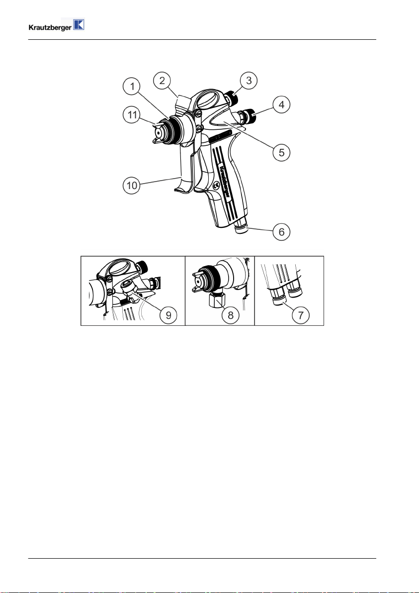
Fig. 1: Overview
1 Cap nut
2 Fluid connection, flow (variant 200-0137 and variant 200-0155)
3 Flat jet controller
4 Needle stroke adjustment screw
5 Main element
6 Compressed-air connection
7 Fluid connection (variant 200-0138 and variant 200-0156)
8 Fluid connection, suction (variant 200-0187)
9 Compressed-air connection (variant 090-3566)
10 Pull lever
11 Air nozzle
mail@krautzberger.com, www.krautzberger.com GB–16

Hand-held Spray Gun Mignon 3
ENGLISH
6 Installation
6.1 Safety
Personnel:
Specialised personnel
n
Protective equipment:
The selection of the protective equipment depends on the installation conditions on site. Always
observe the applicable country-specific safety, accident prevention, occupational safety, and environmental protection regulations for the proper selection of the protective equipment.
WARNING!
Risk of injury due to improper installation!
Improper installation may cause serious personal injury or material damage.
Note:
– Ensure ample of space for the installation prior to starting any work.
– Carefully handle open, sharp-edged components.
– Maintain order and cleanliness at the installation site. Components that are loosely
stacked or are scattered around can cause accidents.
– Assemble components properly. Adhere to specified screw tightening torque.
– Secure components against tipping or falling.
– Ensure that the utilised hose lines meet the requirements for pressure, chemical and
mechanical loads. At the same time, adhere to the spray media manufacturer's specifica-
tions in the safety data sheet.
6.2 General installation information
Adhere to the following general information for the installation:
n Only carry out the installation and start of operation according to the steps described in this
operating manual.
n Make sure that the utilised hose lines meet the requirements for pressure, chemical and
mechanical loads.
n Mixing up the air or fluid connections can lead to permanent damage to the spray gun.
n Reduce the supply air through the installation of a pressure regulator to a maximum of 6 bar.
n Make sure that the connected compressed air is oil-free and free of solid matter.
n Operate the spray gun with processed, dried compressed air (air quality pursuant to DIN ISO
8573-1: grade 4).
n Never point the compressed air at living beings.
200-0137 ■ 200-0138 ■ 200-0187 ■ 090-3566 ■ 200-0155 ■ 200-0156
GB–17

Operating instructions
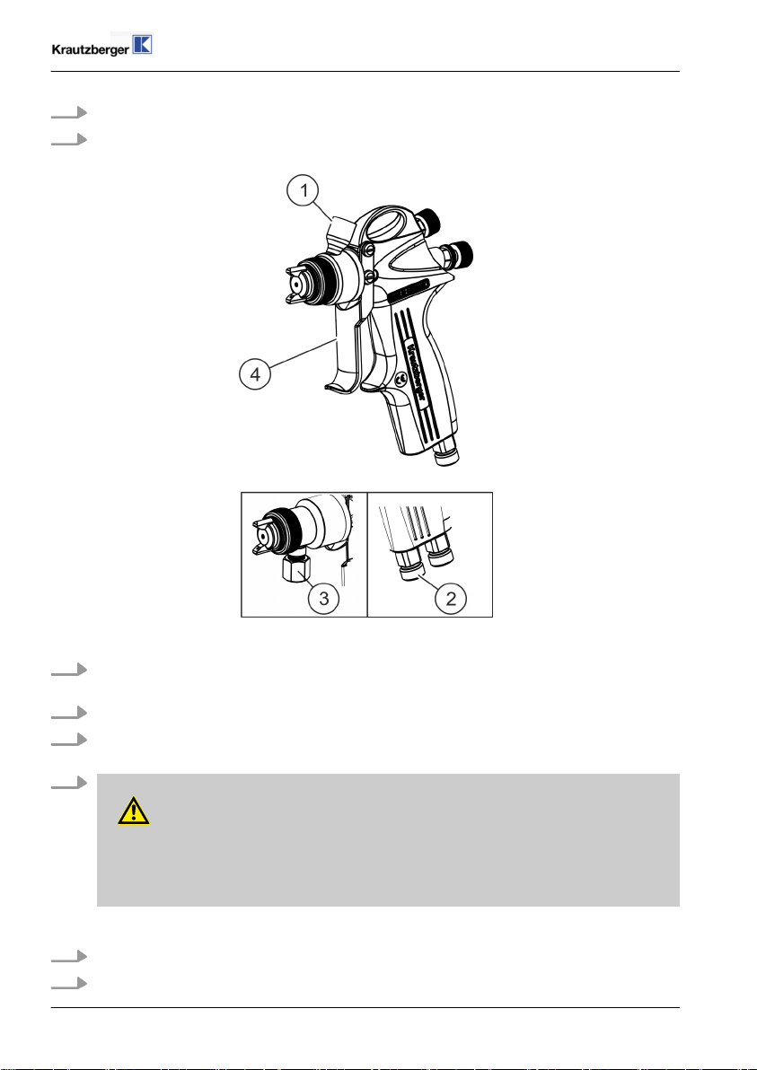
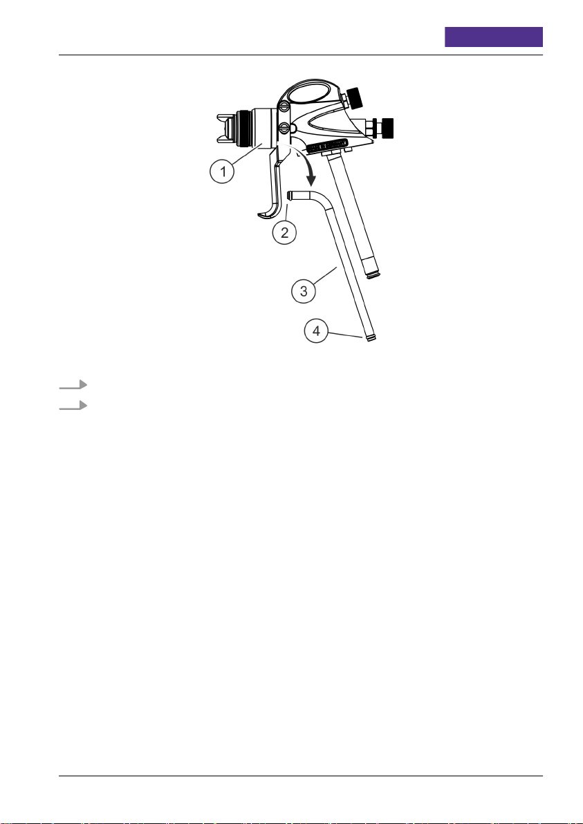
6.3 Connections of the hand-held spray gun
T-Dok-198-GB-Rev.3
Fig. 2: Connections
1. Depending on the design, connect the compressed-air line to the compressed air connection ( Fig. 2/2 or 5) of the hand-held spray gun.
2. Establish material supply, depending on the design, through gravity feed cup ( Fig. 2/1),
suction cup ( Fig. 2/4) or hose ( Fig. 2/3).
mail@krautzberger.com, www.krautzberger.com GB–18

Hand-held Spray Gun Mignon 3
ENGLISH
7 Operation
7.1 Safety
Personnel:
User
n
Specialised personnel
n
Protective equipment:
The selection of the personal protective equipment depends on the utilised medium of the system
owner. The information provided by the medium manufacturer indicated on the safety data sheet
must be adhered to in order to ensure the proper selection of personal protective equipment.
WARNING!
Risk of death, risk of injury or property damage due to hazardous media!
Potential consequences: The application of hazardous media can lead to death, severe injuries or property damage.
When handling hazardous substances, ensure that the current safety data sheets of the hazardous substance manufacturer are available. The necessary measures can be derived from
the content of the safety data sheet. Since the hazardous potential of a material can be reassessed at any time due to lessons learned, the safety data sheet must be checked regularly
and replaced if necessary.
The system owner is responsible for the presence and the up-to-date status of the safety data
sheet and the associated generation of the risk assessment of the effected workstations.
CAUTION!
Risk of injury caused by compressed air!
Uncontrolled leaks of compressed air can lead to serious injuries.
Note:
– Prior to any work on the device/machine, all compressed-air lines must be closed and
disconnected.
– Never point compressed air at living beings.
200-0137 ■ 200-0138 ■ 200-0187 ■ 090-3566 ■ 200-0155 ■ 200-0156
GB–19

Operating instructions
T-Dok-198-GB-Rev.3
WARNING!
Risk of fatal injury, risk of injury or property damage due to damaged or disconnected
lines!
Damaged or disconnected lines can cause death, serious injuries or property damage due to
whip-like movements and the spraying of fluids.
Note:
– Check the fluid pressure lines for damage and a tight fit prior to every work process.
7.2 General information about start-up / commissioning
Adhere to the following general information for commissioning:
n Only carry out the installation and commissioning of the hand-held spray gun in accordance
with the steps described in this operating manual.
n Check the material and compressed air hose lines for damage and tight fit before each use.
n Always observe the applicable country-specific safety, accident prevention, occupational
safety, and environmental protection regulations applicable for the area of use for the handheld spray gun.
n Do not use sharply abrasive, chemically aggressive, very hot or very cold spray media without
first consulting with and receiving approval from Krautzberger GmbH.
n Adhere to the safety data sheets of the spray media manufacturer.
n Only operate the hand-held spray gun in compliance with the values specified in (
13 ‘Technical data’ on page 55).
n Never point the compressed air or the spray jet at living beings.
n Only use sufficiently sturdy hoses! Check and, if necessary, replace older hoses before
starting up the hand-held spray gun.
n Only use hoses that match the hose connections and check them for their proper seat and
ensure that they are leak-proof.
n It is recommended to flush the hand-held spray gun prior to commissioning using a suitable
cleaning product (spraying process with cleaning product, until it runs clear when exiting).
n To ensure that there are no particles clogging the nozzles, we recommend to clean the
coating material with a material filter positioned in front of the fluid connection (high pressure
material filters can be purchased from Krautzberger GmbH).
n To achieve a unified coating thickness and spray pattern for high-quality coatings, a cross-
coating process is recommended, which means that the area is first coated in horizontal lines
and then in vertical lines.
Ä
Chapter
Among other factors, the spray pattern depends on the viscosity of the coating material. It can
be modified through the fluid pressure. If the optimal application cannot be achieved through
fluid pressure changes, it is recommended to try again with a different fluid nozzle.
mail@krautzberger.com, www.krautzberger.com GB–20

Hand-held Spray Gun Mignon 3
ENGLISH
7.3 Operation
1. Switch on the compressed air supply.
2. Where applicable, switch on fluid pressure pump or pressurised fluid container for spray
media.
3. Point the hand-held spray gun at a test surface.
Fig. 3: Pull lever
4.
WARNING!
Sound pressure level
Depending on the operating conditions, the sound pressure of the hand-held spray gun
may cause hearing damage.
Start spraying process by activating the pull lever ( Fig. 3/1).
5.
Adjust the spray pattern ( Ä Chapter 7.4 ‘Adjusting the spray pattern’ on page 21).
6. End the spraying process by releasing the pull lever ( Fig. 3/1).
7.4 Adjusting the spray pattern
A wide range of air and material nozzles in various sizes are available to perform numerous differing coating tasks. There are four different families for the nozzles:
Nozzle type Description Remark
Round jet Cone-shaped stream in front of the
nozzle
Flat jet Width-adjustable jet for flat-shaped
application
200-0137 ■ 200-0138 ■ 200-0187 ■ 090-3566 ■ 200-0155 ■ 200-0156
A closed flat jet regulator creates
round jet
GB–21

Operating instructions
T-Dok-198-GB-Rev.3
Nozzle type Description Remark
Rotary jet Rotary impulse creates strongly
twisting spray stream
Full-cone rotary
jet
Rotary impulse creates twisting spray
stream
suitable for difficult workpiece geometries (angles, etc.)
suitable for difficult workpiece geometries (undercuts, etc.)
Option for spray pattern adjustment
Excessive air pressure not only causes unnecessarily high air consumption but also a high
atomisation of the coating material. It is recommended that you first adjust the spray pattern
by varying the air and coating material pressure. If you cannot achieve satisfactory results this
way, you should experiment with other nozzle sizes.
mail@krautzberger.com, www.krautzberger.com GB–22

Hand-held Spray Gun Mignon 3
ENGLISH
1. Adjust atomiser air pressure.
2. Adjust coating material pressure when supplied by pumps or pressure container.
Adjustment only possible when supplied by pumps or pressure container.
Fig. 4: Adjusting the spray pattern
3. Adjust needle stroke with adjustment screw ( Fig. 4/2) on the spray gun.
4. Adjust width of the spray stream with flat jet regulator ( Fig. 4/1).
Adjustment only possible for flat jet nozzles.
200-0137 ■ 200-0138 ■ 200-0187 ■ 090-3566 ■ 200-0155 ■ 200-0156
GB–23

Operating instructions
7.5 Shutting down
7.5.1 Temporary shut-down
Fig. 5: Temporary shut-down
1. Disrupt the spraying process by releasing the pull lever ( Fig. 5/1).
2. Close the material supply and switch off the fluid pressure pump if necessary.
3. Release the residual energy by activating the pull lever ( Fig. 5/1).
7.5.2 Long-term shut-down
T-Dok-198-GB-Rev.3
Fig. 6: Long-term shut-down
mail@krautzberger.com, www.krautzberger.com GB–24

Hand-held Spray Gun Mignon 3
1. Disrupt the spraying process by releasing the pull lever ( Fig. 6/1).
2. Close the material supply and switch off the fluid pressure pump if necessary.
3. Release the residual energy by activating the pull lever ( Fig. 6/1).
4.
Empty gravity feed cup or unscrew suction cup and clean hand-held spray gun ( Ä Chapter
8.4 ‘Cleaning the hand-held spray gun’ on page 27).
5.
DANGER!
Risk of fatal injury due to toxic, flammable or explosive material
High risk potential during the storage and transport of the hand-held spray gun still
containing toxic, flammable or explosive material or cleaning products.
– Properly clean the hand-held spray gun before storage and transport so that there
is no toxic, flammable or explosive products inside.
Clean parts with adhering residual material in an appropriate manner.
ENGLISH
200-0137 ■ 200-0138 ■ 200-0187 ■ 090-3566 ■ 200-0155 ■ 200-0156
GB–25

Operating instructions
T-Dok-198-GB-Rev.3
8 Maintenance
8.1 Safety
Personnel:
Operator
n
Qualified personnel
n
Protective equipment:
The selection of the protective equipment depends on the maintenance conditions on site and the
medium utilized by the system owner. The applicable country-specific safety, accident prevention,
occupational safety, and environmental protection regulations must adhered to for the proper
selection of the protective equipment and the information given by the spray media manufacturer
on the safety data sheet must be taken into consideration.
WARNING!
Risk of injury through the use of incorrect spare parts!
The use of incorrect or defective spare parts can cause hazards for the personnel as well as
damage, malfunctions or complete failure.
– Only use OEM parts from Krautzberger or Krautzberger-approved spare parts.
– In case of questions, always contact our Customer Care department.
8.2 General maintenance information
The spray gun is not subject to any regular maintenance intervals.
Wear parts such as seals, nozzles, and needles should be checked in regular intervals and
replaced if necessary for trouble-free operation. The level of wear depends on the abrasiveness of
the spray fluid used. Escaping air and spray fluid as well as the deterioration of the spray pattern
are signs that parts are worn.
8.3 Maintenance schedule
Interval Maintenance work Personnel
After each use
if needed
Clean handheld spray gun ( Ä Chapter 8.4
‘Cleaning the hand-held spray gun’ on page 27)
Change fluid and air nozzle ( Ä Chapter 8.6
‘Changing the material nozzle and the air
nozzle’ on page 34)
Change fluid needle ( Ä Chapter 8.5 ‘Changing
the fluid needle’ on page 30)
Change sealing cone ( Ä Chapter 8.7
‘Changing the sealing cone’ on page 36)
Change O-ring in air connection ( Ä Chapter
8.8 ‘Changing O-ring in air connection’
on page 38)
Operator
Qualified personnel
mail@krautzberger.com, www.krautzberger.com GB–26

Hand-held Spray Gun Mignon 3
Interval Maintenance work Personnel
Change needle packing ( Ä Chapter 8.9
‘Changing needle pack’ on page 40)
Change O-ring in the locking part ( Ä Chapter
8.10 ‘Changing O-ring in the locking piece’
on page 42)
Change O-ring in the flat jet regulator (
Ä
Chapter 8.11 ‘Changing O-ring in the flat jet
regulator’ on page 44)
Change O-ring in the fluid pipe (only for
200-0138) ( Ä Chapter 8.12 ‘Changing O-ring
in the fluid pipe’ on page 45)
8.4 Cleaning the hand-held spray gun
WARNING!
Danger of injury due to improper cleaning!
– Observe the safety data sheets of the medium manufacturer.
– Observe the safety data sheets of the cleaning product manufacturer.
– Do not use any halogenated cleaning products.
ENGLISH
200-0137 ■ 200-0138 ■ 200-0187 ■ 090-3566 ■ 200-0155 ■ 200-0156
GB–27
Operating instructions
1.
Interrupt the operation ( Ä Chapter 7.5 ‘Shutting down’ on page 24).
T-Dok-198-GB-Rev.3
2. If necessary, secure fluid pressure pump or pressurised fluid container for the spray media
against restart.
Fig. 7: Cleaning the hand-held spray gun
3. Connect a container with detergent to the fluid connection ( Fig. 7/1, 2 or 3) or fill cup with
detergent fluid.
4. Switch on the compressed air supply.
5. Where applicable, switch on fluid pressure pump or pressurised fluid container for spray
media.
6.
WARNING!
Sound pressure level
Depending on the operating conditions, the sound pressure of the hand-held spray gun
may cause hearing damage.
Start spraying process by activating the pull lever ( Fig. 7/4).
7. Spray until the cleaning product runs clear.
8. End the spraying process by releasing the pull lever ( Fig. 7/4).
mail@krautzberger.com, www.krautzberger.com GB–28

Hand-held Spray Gun Mignon 3
ENGLISH
9. End the supply of the cleaning product.
10. Blow out the cleaning product remains by briefly pulling the pull lever ( Fig. 7/4).
11. Switch off the compressed air supply and secure it against restart.
12.
NOTICE!
Never immerse the entire hand-held spray gun in solvent. This could destroy the seals
and rinse off the lubricant.
Clean the outside of the hand-held spray gun with a cloth soaked in cleaning product.
200-0137 ■ 200-0138 ■ 200-0187 ■ 090-3566 ■ 200-0155 ■ 200-0156
GB–29

Operating instructions
T-Dok-198-GB-Rev.3
8.5 Changing the fluid needle
Disassembly
1.
Interrupt the operation ( Ä Chapter 7.5 ‘Shutting down’ on page 24).
2. If necessary, secure fluid pressure pump or pressurised fluid container for the spray media
against restart.
3. Interrupt the external material supply.
Fig. 8: Removing the fluid needle
4. To reduce the pre-tensioning of the spring ( Fig. 8/2), unscrew the needle stroke adjustment
screw ( Fig. 8/4) on the locking piece ( Fig. 8/3) to the end stop.
5. Unscrew the locking piece ( Fig. 8/3) with a fork wrench.
6.
CAUTION!
Risk of injury due to fluid needles!
Remove the spring ( Fig. 8/2) and the fluid needle ( Fig. 8/1).
Fig. 9: Fluid needle
mail@krautzberger.com, www.krautzberger.com GB–30

Hand-held Spray Gun Mignon 3
ENGLISH
7. Loosen the needle pusher ( Fig. 9/2) and unscrew the fluid needle ( Fig. 9/1) from the
needle bolt ( Fig. 9/3).
200-0137 ■ 200-0138 ■ 200-0187 ■ 090-3566 ■ 200-0155 ■ 200-0156
GB–31

Operating instructions
Installation
Fig. 10: Fluid needle
1.
CAUTION!
Risk of injury due to fluid needles!
Screw fluid needle ( Fig. 10/1) into needle bolt ( Fig. 10/3) and needle pusher ( Fig. 10/2).
T-Dok-198-GB-Rev.3
Fig. 11: Needle dimension
2. Adjust needle dimension ( Fig. 11/I or II) and tighten needle pusher:
n I: Needle dimension without piercing pin
n II: Needle dimension with piercing pin
n lll: Needle dimension valid for variant 200-0187
mail@krautzberger.com, www.krautzberger.com GB–32

Hand-held Spray Gun Mignon 3
Fig. 12: Attaching the fluid needle
3. Carefully insert fluid needle ( Fig. 12/1) and spring ( Fig. 12/2).
4.
WARNING!
Risk of injury through the use of incorrect spare parts!
ENGLISH
If necessary, replace the O-ring ( Fig. 12/3). For that, turn the adjustment screw up to the
end stop in the locking piece.
Lightly grease O-ring. We recommend Krautzberger special grease (contact data see
last page).
Unscrew adjustment screw all the way to the end position.
5.
6. Screw in locking piece ( Fig. 12/4) and tighten with a fork wrench.
7.
Adjust spray pattern with needle stroke adjustment screw ( Fig. 12/5) (
Ä
‘Adjusting the spray pattern’ on page 21).
200-0137 ■ 200-0138 ■ 200-0187 ■ 090-3566 ■ 200-0155 ■ 200-0156
Chapter 7.4
GB–33

Operating instructions
T-Dok-198-GB-Rev.3
8.6 Changing the material nozzle and the air nozzle
Disassembly
1.
Interrupt the operation ( Ä Chapter 7.5 ‘Shutting down’ on page 24).
2. If necessary, secure fluid pressure pump or pressurised fluid container for the spray media
against restart.
3. Interrupt the external material supply.
Fig. 13: Removing the material nozzle and the air nozzle
4. Loosen cap nut ( Fig. 13/1).
5. Remove the air nozzle ( Fig. 13/2).
6. Activate and hold the pull lever ( Fig. 13/5).
7. Unscrew the fluid nozzle ( Fig. 13/3) with a fork wrench.
Always replace fluid nozzle ( Fig. 13/3) and fluid needle ( Fig. 13/4) at the same time.
mail@krautzberger.com, www.krautzberger.com GB–34

Hand-held Spray Gun Mignon 3
Installation
Fig. 14: Installing the material nozzle and the air nozzle
1. Activate and hold the pull lever ( Fig. 14/5).
2.
WARNING!
Risk of injury through the use of incorrect spare parts!
ENGLISH
Tighten the new fluid nozzle ( Fig. 14/3).
3. Release the pull lever ( Fig. 14/5).
4.
WARNING!
Risk of injury through the use of incorrect spare parts!
Attach the new air nozzle ( Fig. 14/2) and tighten it with the cap nut ( Fig. 14/1).
200-0137 ■ 200-0138 ■ 200-0187 ■ 090-3566 ■ 200-0155 ■ 200-0156
GB–35

Operating instructions
T-Dok-198-GB-Rev.3
8.7 Changing the sealing cone
Disassembly
1.
Remove the fluid needle ( Ä Chapter 8.5 ‘Changing the fluid needle’ on page 30).
2. Pull and hold the pull lever.
Fig. 15: Dismantling the sealing cone
3. Remove the spring ( Fig. 15/4).
4. Pull out sealing bushing ( Fig. 15/3) and sealing cone ( Fig. 15/2) using the dismantling tool.
5. Take out sealing ( Fig. 15/1) and check for wear, replace if necessary.
mail@krautzberger.com, www.krautzberger.com GB–36

Hand-held Spray Gun Mignon 3
Installation
Fig. 16: Installing the sealing cone
1.
WARNING!
Risk of injury through the use of incorrect spare parts!
Insert sealing ( Fig. 16/1).
ENGLISH
Lightly grease the sealing ( Fig. 16/1). We recommend Krautzberger special grease
(contact data see last page).
2. Insert the sealing cone ( Fig. 16/2) and the sealing bushing ( Fig. 16/3).
Lightly grease the sealing cone ( Fig. 16/2). We recommend Krautzberger special
grease (contact data see last page).
Insert spring ( Fig. 16/4).
3.
4.
Attach the fluid needle ( Ä Chapter 8.5 ‘Changing the fluid needle’ on page 30).
200-0137 ■ 200-0138 ■ 200-0187 ■ 090-3566 ■ 200-0155 ■ 200-0156
GB–37

Operating instructions
T-Dok-198-GB-Rev.3
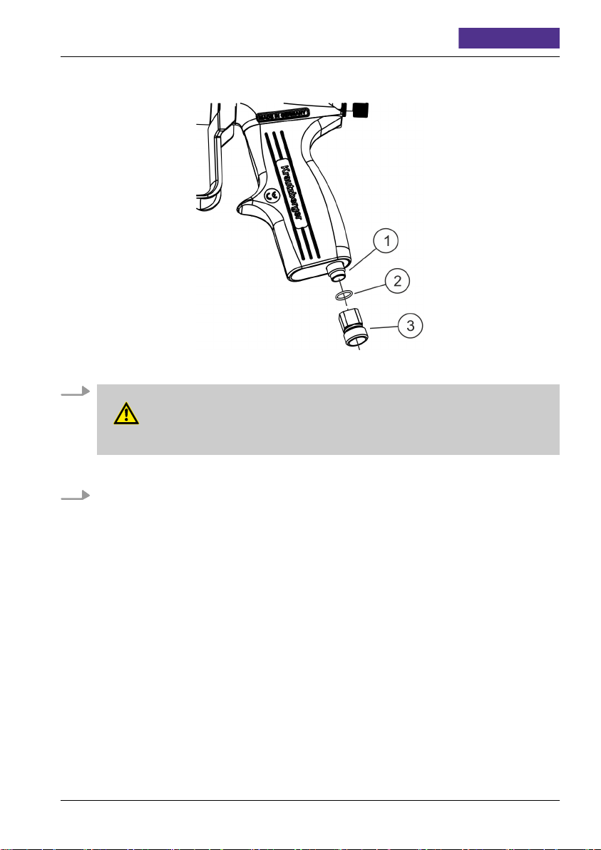
8.8 Changing O-ring in air connection
Disassembly
1.
Interrupt the operation ( Ä Chapter 7.5 ‘Shutting down’ on page 24).
2. If necessary, secure fluid pressure pump or pressurised fluid container for the spray media
against restart.
3. Interrupt the external material supply.
Fig. 17: Removing the O-ring
4. Unscrew double nipple ( Fig. 17/3) of the air connection ( Fig. 17/1) with suitable fork
wrench.
5. Remove O-ring ( Fig. 17/2) from the double nipple ( Fig. 17/3).
mail@krautzberger.com, www.krautzberger.com GB–38
Hand-held Spray Gun Mignon 3
Installation
Fig. 18: Installing the O-ring
1.
WARNING!
Risk of injury through the use of incorrect spare parts!
ENGLISH
Insert new O-ring ( Fig. 18/2) into the double nipple ( Fig. 18/3).
2. Tighten double nipple ( Fig. 18/3) with a suitable fork wrench.
200-0137 ■ 200-0138 ■ 200-0187 ■ 090-3566 ■ 200-0155 ■ 200-0156
GB–39

Operating instructions
8.9 Changing needle pack
Disassembly
1.
Remove the fluid needle ( Ä Chapter 8.5 ‘Changing the fluid needle’ on page 30).
2.
Remove the fluid nozzle ( Ä Chapter 8.6 ‘Changing the material nozzle and the air nozzle’
on page 34).
T-Dok-198-GB-Rev.3
Fig. 19: Dismantling the needle pack
3. Loosen sealing screw ( Fig. 19/1) with a suitable screw driver.
4. Remove the seal ( Fig. 19/2).
Pay attention to position of seal!
5. Remove the needle guide ( Fig. 19/3).
mail@krautzberger.com, www.krautzberger.com GB–40

Hand-held Spray Gun Mignon 3
Installation
Fig. 20: Installing the needle pack
1.
WARNING!
Risk of injury through the use of incorrect spare parts!
ENGLISH
Insert new needle guide ( Fig. 20/3).
2.
WARNING!
Risk of injury through the use of incorrect spare parts!
Insert new seal ( Fig. 20/2).
Pay attention to position of seal!
3. Tighten sealing screw ( Fig. 20/1) with a suitable screw driver.
4.
Attach the fluid nozzle ( Ä Chapter 8.6 ‘Changing the material nozzle and the air nozzle’
on page 34).
200-0137 ■ 200-0138 ■ 200-0187 ■ 090-3566 ■ 200-0155 ■ 200-0156
GB–41

Operating instructions
5.
Attach the fluid needle ( Ä Chapter 8.5 ‘Changing the fluid needle’ on page 30).
6.
Attach the fluid nozzle ( Ä Chapter 8.6 ‘Changing the material nozzle and the air nozzle’
T-Dok-198-GB-Rev.3
on page 34).
7.
Attach the fluid needle (
Ä
Chapter 8.5 ‘Changing the fluid needle’ on page 30).
8.10 Changing O-ring in the locking piece
Disassembly
1.
Interrupt the operation ( Ä Chapter 7.5 ‘Shutting down’ on page 24).
2. If necessary, secure fluid pressure pump or pressurised fluid container for the spray media
against restart.
3. Interrupt the external material supply.
Fig. 21: Removing the O-ring
4. To reduce the pre-tensioning of the spring ( Fig. 21/1), unscrew the needle stroke adjustment screw ( Fig. 21/4) on the locking piece ( Fig. 21/3) to the end stop.
5. Unscrew the locking piece ( Fig. 21/3) with a fork wrench.
6. Remove the O-ring ( Fig. 21/2). For that, turn the adjustment screw ( Fig. 21/4) up to the
end stop in the locking piece.
mail@krautzberger.com, www.krautzberger.com GB–42

Hand-held Spray Gun Mignon 3
Installation
Fig. 22: Removing the O-ring
1.
WARNING!
Risk of injury through the use of incorrect spare parts!
Insert new O-ring ( Fig. 22/1).
ENGLISH
Lightly grease the O-ring ( Fig. 22/1). We recommend Krautzberger special grease
(contact data see last page).
Unscrew adjustment screw ( Fig. 22/3) all the way to the end position.
2.
3. Screw in locking piece ( Fig. 22/2) and tighten with a fork wrench.
4.
Adjust spray pattern with needle stroke adjustment screw ( Ä Chapter 7.4 ‘Adjusting the
spray pattern’ on page 21).
200-0137 ■ 200-0138 ■ 200-0187 ■ 090-3566 ■ 200-0155 ■ 200-0156
GB–43
Operating instructions
T-Dok-198-GB-Rev.3
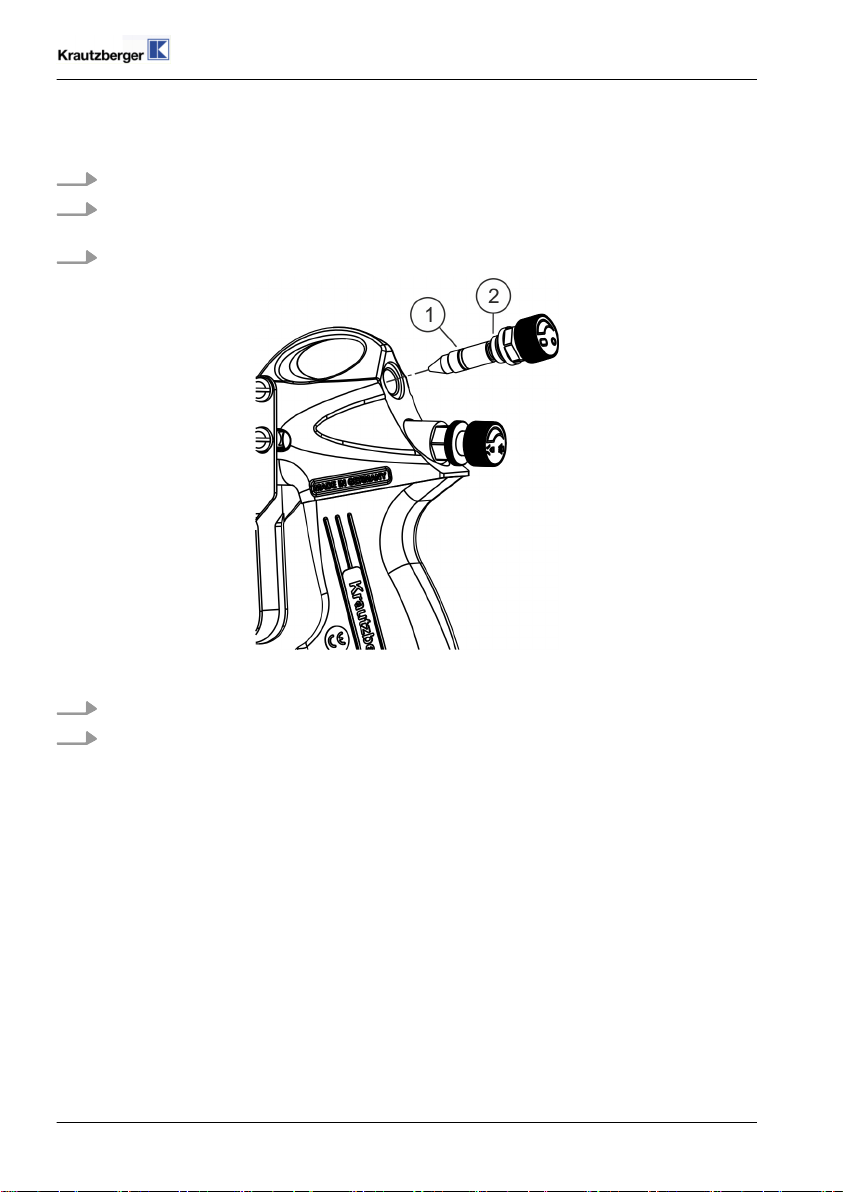
8.11 Changing O-ring in the flat jet regulator
Disassembly
1.
Interrupt the operation ( Ä Chapter 7.5 ‘Shutting down’ on page 24).
2. If necessary, secure fluid pressure pump or pressurised fluid container for the spray media
against restart.
3. Interrupt the external material supply.
Fig. 23: Removing the O-ring
4. Dismantle flat jet regulator ( Fig. 23/2) with a suitable fork wrench.
5. Remove the O-ring ( Fig. 23/1).
mail@krautzberger.com, www.krautzberger.com GB–44
Hand-held Spray Gun Mignon 3
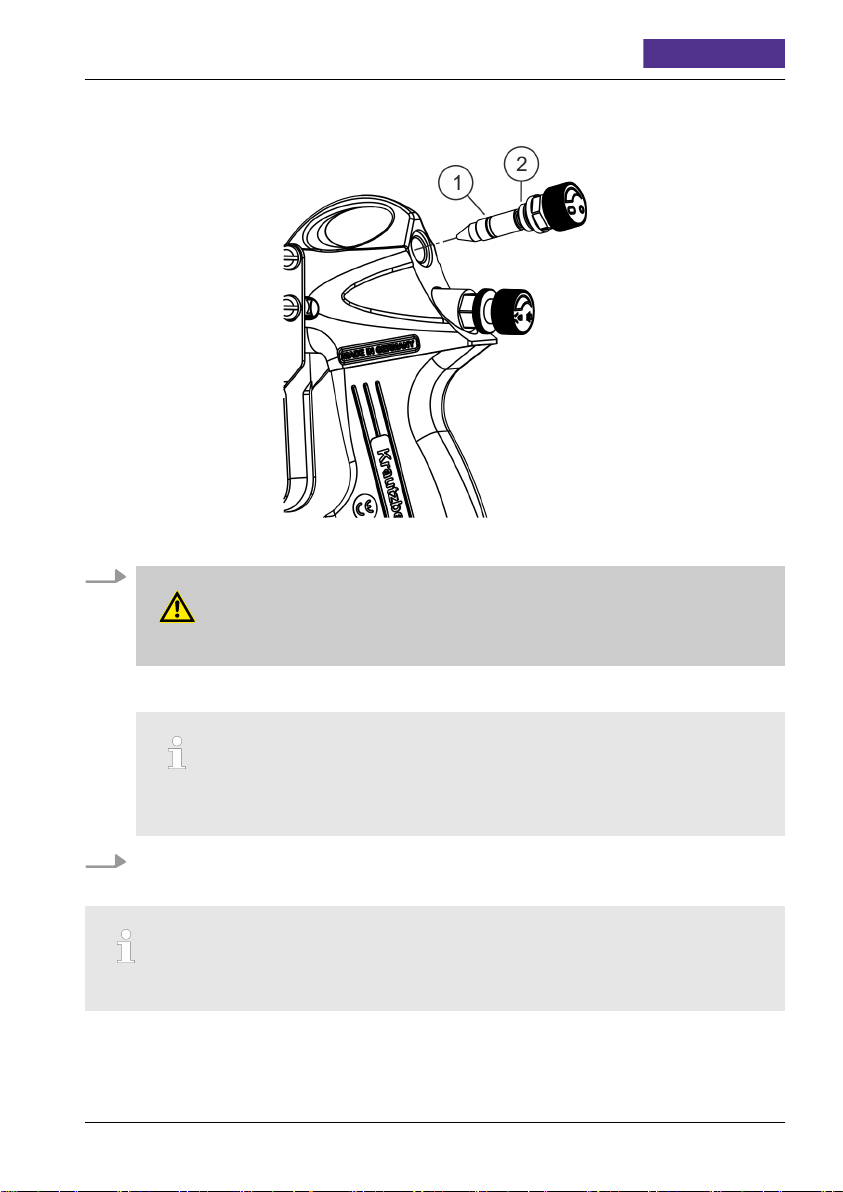
Installation
Fig. 24: Installing the O-ring
1.
WARNING!
Risk of injury through the use of incorrect spare parts!
ENGLISH
Insert new O-ring ( Fig. 24/1).
Lightly grease the O-ring ( Fig. 24/1). We recommend Krautzberger special grease
(contact data see last page).
2. Tighten flat jet regulator ( Fig. 24/2) with a suitable fork wrench.
8.12 Changing O-ring in the fluid pipe
This work step is only valid for variant
200-0137 ■ 200-0138 ■ 200-0187 ■ 090-3566 ■ 200-0155 ■ 200-0156
200-0138 and 200-0156!
GB–45

Operating instructions
T-Dok-198-GB-Rev.3
Disassembly
1.
Interrupt the operation ( Ä Chapter 7.5 ‘Shutting down’ on page 24).
2. If necessary, secure fluid pressure pump or pressurised fluid container for the spray media
against restart.
3. Interrupt the external material supply.
Fig. 25: Dismantle the handle
4. Loosen double nipple air connection ( Fig. 25/2) with a suitable fork wrench.
5. Pull off handle ( Fig. 25/1).
The material connection nipple ( Fig. 25/3) will be pulled off at the same time
mail@krautzberger.com, www.krautzberger.com GB–46
Hand-held Spray Gun Mignon 3
Fig. 26: Dismantling the fluid pipe
6. Pull fluid pipe ( Fig. 26/3) from head piece ( Fig. 26/1) and remove it.
7. Dismantle O-rings ( Fig. 26/2 and 4) from fluid pipe ( Fig. 26/3).
ENGLISH
200-0137 ■ 200-0138 ■ 200-0187 ■ 090-3566 ■ 200-0155 ■ 200-0156
GB–47

Installation
Fig. 27: Installing fthe luid pipe
1.
WARNING!
Risk of injury through the use of incorrect spare parts!
Operating instructions
T-Dok-198-GB-Rev.3
Attach new O-rings ( Fig. 27/2 and 4) to fluid pipe.
2. Carefully insert fluid pipe ( Fig. 27/3) in head piece ( Fig. 27/1).
mail@krautzberger.com, www.krautzberger.com GB–48

Hand-held Spray Gun Mignon 3
ENGLISH
Fig. 28: Assembling the handle
3. Place handle ( Fig. 28/1) and material connection nipple ( Fig. 28/3) onto the fluid pipe.
4. Tighten double nipple air connection ( Fig. 28/2) with a suitable fork wrench.
Check O-ring air connection and renew if necessary.
200-0137 ■ 200-0138 ■ 200-0187 ■ 090-3566 ■ 200-0155 ■ 200-0156
GB–49

Operating instructions
T-Dok-198-GB-Rev.3
9 Troubleshooting
Personnel:
Qualified personnel
n
If the fault is not included in the following tables or if it cannot be eliminated with the measures
described, contact Krautzberger Customer Care.
Troubleshooting table
Spray pattern Error Cause Remedy
Normal flat jet spray pattern
Spray pattern too
heavy towards the top
and towards the
bottom
Spray pattern concentrated on the left or
right side
Heavy application in
the centre of the spray
pattern
Split spray pattern
n Dirty air nozzle
n Dirty fluid nozzle
n Dirty air nozzle
n Dirty fluid nozzle
Clean nozzles ( Ä Chapter
8.4 ‘Cleaning the hand-held
spray gun’ on page 27).
Clean nozzles ( Ä Chapter
8.4 ‘Cleaning the hand-held
spray gun’ on page 27).
n Too much material n Reduce material supply
n Material too thick n Thin material
n Insufficient mate-
rial
n Flat jet air pres-
sure too high
n Increase material
supply
n Reduce flat jet air pres-
sure
mail@krautzberger.com, www.krautzberger.com GB–50

Hand-held Spray Gun Mignon 3
Spray pattern Error Cause Remedy
Spray pattern too thin
n Cap nut loose n Tighten cap nut
ENGLISH
Fluid jet comes out in
spurts or rapid bursts
Leakage on the
clamping screw
Fluid nozzle drips
9.1 Customer Care
Krautzberger GmbH
Customer service
Stockbornstr. 13
65343 Eltville am Rhein
+49 6123 - 698151
customercare@krautzberger.com
n Insufficient mate-
rial supply
n Increase material
supply
n Blocked fluid path n Clean
n Loose or dam-
aged fluid nozzle
n Tighten or replace (
Ä
Chapter 8.6
‘Changing the material
nozzle and the air
nozzle’ on page 34).
n Worn needle seal n Replace needle seal
n Needle seal
n Replace needle seal
defective
n Worn or damaged
fluid needle
n Change fluid needle (
Ä
Chapter 8.5
‘Changing the fluid
needle’ on page 30).
n Dirty or damaged
fluid nozzle
n Clean ( Ä Chapter 8.4
‘Cleaning the hand-held
spray gun’ on page 27)
or replace ( Ä Chapter
8.6 ‘Changing the
material nozzle and the
air nozzle’ on page 34)
fluid nozzle.
200-0137 ■ 200-0138 ■ 200-0187 ■ 090-3566 ■ 200-0155 ■ 200-0156
GB–51

Operating instructions
10 Spare parts
– Only use OEM parts from Krautzberger or Krautzberger-approved spare parts.
– In case of questions, always contact our Customer Care department.
Spare parts order – General
To make spare part ordering easier, please provide the following information:
– Serial number
– Model / product name
– Designation
– Item number according to spare parts list
– Quantity
– Desired shipping method (post, freight, sea, air, express)
– Delivery address
T-Dok-198-GB-Rev.3
A complete spare part overview is available on the website of Krautzberger GmbH:
www.krautzberger.de
mail@krautzberger.com, www.krautzberger.com GB–52

Hand-held Spray Gun Mignon 3
ENGLISH
11 Accessories
A wide range of accessories are available for the spray gun. For further information, visit us on the
Internet (www.krautzberger.com) or contact your Krautzberger dealer, consultant or our office staff.
Here are a few examples:
n Gravity feed cup
n Suction cup
n Nozzle extensions
n Various air connection options
n Tool bag
– Screwdriver SW 6
– Socket wrench SW 4
– Open-ended wrench SW 6
– Open-ended wrench SW 7
– Open-ended wrench SW 11
– Dismantling tool
n etc.
200-0137 ■ 200-0138 ■ 200-0187 ■ 090-3566 ■ 200-0155 ■ 200-0156
GB–53

Operating instructions
T-Dok-198-GB-Rev.3
12 Disassembly and disposal
12.1 Safety
Personnel:
Qualified personnel
n
Protective equipment:
The selection of the protective equipment depends on the installation conditions on site and the
medium utilized by the system owner. The applicable country-specific safety, accident prevention,
occupational safety, and environmental protection regulations must adhered to for the proper
selection of the protective equipment and the information given by the spray media manufacturer
on the safety data sheet must be taken into consideration.
12.2 Disassembly
WARNING!
Risk of injury due to improper disassembly!
Prior to starting the disassembly:
n Switch off the device and secure it against restart.
n Physically disconnect the entire power supply from the device, and discharge any energy
stored in the machine.
n Remove and dispose of operating and auxiliary material as well as remaining processing
materials in an environmentally friendly manner.
Afterwards, properly clean components and modules and take them apart in compliance with applicable local occupational health & safety regulations as well as environmental protection regulations.
12.3 Disposal
If no return or disposal agreement has been made, recycle the dismantled parts:
n Scrap metals.
n Recycle plastic components.
n Sort remaining components based on the respective material and dispose of them accord-
ingly.
n Properly dispose of potential spray fluid residue separately from the device.
If in doubt, obtain information about environmentally-appropriate disposal with the local municipalities or specialised disposal companies.
mail@krautzberger.com, www.krautzberger.com GB–54

Hand-held Spray Gun Mignon 3
ENGLISH
13 Technical data
13.1 Dimensions and weight
Specification Design Value Unit
Width 200-0137 30 mm
200-0138
200-0155
200-0156
200-0187
090-3566 42
Height 200-0137 160 mm
200-0138 163.5
200-0155 160
200-0156 163.5
200-0187 158
090-3566 170
Length 128 - 131 mm
Fluid connection (on the handle) G 1/4 " male
Fluid connection (flow design) M12x1.5 female
Atomiser air Sleeve NW (8/9), G1/4 " male
Weight without fluid container approx. 350 g
13.2 General specifications
Specification Value Unit
Air consumption (depending on
length and nominal width of the
air hose and the utilized nozzle
set)
Max. fluid pressure 0.4 Mpa (4
Max. material temperature (8 hours continuous
use)
Max. atomiser air pressure 0.6 Mpa (6
Reach distance of the spray jet (depending on nozzles and coating material)
Sound pressure level (depends on the nozzle) 73-96 dB (A)
Vibration < 2.5
Angle of spray jet in front of nozzle up to approx. 90 °C
200-0137 ■ 200-0138 ■ 200-0187 ■ 090-3566 ■ 200-0155 ■ 200-0156
3 bar 225 Nl/min
4 bar 280
5 bar 465
bar)
43 °C
bar)
up to 4 m
m/s
2
GB–55

13.3 Dimensions
Operating instructions
T-Dok-198-GB-Rev.3
Fig. 29: Dimensions variant 200-0137, 200-0155 and variant 200-0138, 200-0156
mail@krautzberger.com, www.krautzberger.com GB–56

Hand-held Spray Gun Mignon 3
ENGLISH
Fig. 30: Dimensions 200-0187 and 090-3566
200-0137 ■ 200-0138 ■ 200-0187 ■ 090-3566 ■ 200-0155 ■ 200-0156
GB–57

Operating instructions
14 Declaration of conformity
T-Dok-198-GB-Rev.3
Fig. 31: Declaration of conformity
mail@krautzberger.com, www.krautzberger.com GB–58

Hand-held Spray Gun Mignon 3
ENGLISH
15 Index
C
Connection values ................................................55
D
Delivery ......................................................15
Dimensions ..................................................55, 56
Disassembly ...................................................54
Disposal ......................................................54
F
Function description ...............................................5
O
Overview .....................................................16
Owner .......................................................14
P
Personal protective equipment .........................................9
Personnel ......................................................8
Product number ..................................................6
Protective equipment ...............................................9
R
Recycling .....................................................54
S
Storage ......................................................15
Symbols
in this manual .................................................7
T
Troubleshooting table ..............................................50
U
Use .........................................................13
User qualification .................................................8
W
Weight .......................................................55
200-0137 ■ 200-0138 ■ 200-0187 ■ 090-3566 ■ 200-0155 ■ 200-0156
GB–59


Krautzberger GmbH
Stockbornstrasse 13
65343 Eltville am Rhein, Germany
Hotline: +49 (0) 6123 698-222
Reception: +49 (0) 6123 698-0
Fax: +49 (0) 6123 698-200
Email: mail@krautzberger.com
Internet: www.krautzberger.com
© Krautzberger GmbH 2017
© Krautzberger GmbH 2017
 Loading...