

GB
Operating instructions
Automatic spray gun M -10
T-Dok-213-GB-Rev.2
■ 200-0142
Translation of the original operating instructions

Thank you for selecting a Krautzberger product.
This product has been manufactured following state-of-the-art manufacturing procedures and
extensive quality assurance measures. We promise you a product of the highest quality.
If you have questions, requests or suggestions, please contact us. We are always glad to assist
you.
Information about the operating manual
This manual provides important information on how to work with the device safely and efficiently.
The manual is part of the device and must always be kept in the immediate proximity of the device
so that it is accessible to the personnel at all times.
The personnel must have read and understood this manual before starting any work. Compliance
with all specified safety information and instructions is a basic requirement for safe working conditions.
In addition, the local occupational safety regulations and general safety rules apply for the area of
application of the device.
Due to optional finishing variants, it is possible that the figures shown in this operating manual
deviate from your device.
Information about explosion protection
Many of our competitors have been marking their products with the Ex symbol as a matter of principle for some time now.
At Krautzberger we do not do that.
We engineer and manufacture our products in line with currently applicable directives.
If the labelling on the product is required, it is affixed to the product as the result of the necessary
analysis of ignition sources. If no labelling is affixed, the analysis of ignition sources and previous
experience with the assessment of the suitability of products for use in a potentially explosive area
have shown that the product described in this operating manual does not represent a potential
source of ignition, with the exception of an electrostatic charge.
Taking into account the potential equalisation (provided by proper earth connection), the use in an
area at risk for explosions is permitted in accordance with the currently valid directives.
GB–2
mail@krautzberger.com, www.krautzberger.com

Automatic spray gun M -10
ENGLISH
Table of contents
1 Function and identification................................................................................................ 5
1.1 Function....................................................................................................................... 5
1.2 Identification................................................................................................................. 6
2 Safety and responsibility................................................................................................... 7
2.1 Symbols in this manual................................................................................................ 7
2.2 Personnel requirements............................................................................................... 8
2.3 Personal protective equipment.................................................................................... 9
2.4 Responsibility of the owner........................................................................................ 10
2.5 Intended use.............................................................................................................. 10
2.6 Predictable misuse.................................................................................................... 10
2.7 General safety information......................................................................................... 11
2.8 Residual risks............................................................................................................ 12
2.9 Course of action in an emergency............................................................................. 13
3 Transport and storage..................................................................................................... 14
3.1 Transport................................................................................................................... 14
3.2 Storage of packaged units......................................................................................... 14
3.3 Packaging.................................................................................................................. 14
4 Overview............................................................................................................................ 15
5 Installation......................................................................................................................... 16
5.1 Safety......................................................................................................................... 16
5.2 General installation information................................................................................. 17
5.3 Connection scheme................................................................................................... 17
5.4 Mounting the automatic spray guns........................................................................... 19
5.5 Connecting the automatic spray gun......................................................................... 19
6 Operation........................................................................................................................... 21
6.1 Safety......................................................................................................................... 21
6.2 General information about the start-up...................................................................... 23
6.3 Shutting down............................................................................................................ 23
6.4 Start of operation....................................................................................................... 24
6.5 Adjusting the spray pattern........................................................................................ 24
6.6 Adjusting the needle stroke....................................................................................... 25
7 Maintenance...................................................................................................................... 26
7.1 Safety......................................................................................................................... 26
7.2 Maintenance schedule............................................................................................... 27
7.3 Cleaning..................................................................................................................... 27
7.4 Changing the air and fluid nozzles............................................................................. 29
7.5 Changing the fluid needle.......................................................................................... 29
■ 200-0142
GB–3

Operating instructions
T-Dok-213-GB-Rev.2
7.6 Changing needle seals.............................................................................................. 33
8 Troubleshooting............................................................................................................... 36
8.1 Customer Care.......................................................................................................... 38
9 Spare parts........................................................................................................................ 39
9.1 Spare parts................................................................................................................ 39
10 Accessories...................................................................................................................... 40
11 Disassembly and disposal............................................................................................... 41
11.1 Safety....................................................................................................................... 41
11.2 Disassembly............................................................................................................ 41
11.3 Disposal................................................................................................................... 41
12 Technical data................................................................................................................... 43
12.1 Dimensions and weight............................................................................................ 43
12.2 General specifications............................................................................................. 43
12.3 Dimensions.............................................................................................................. 44
13 Declaration of incorporation........................................................................................... 45
14 Notes.................................................................................................................................. 46
15 Index.................................................................................................................................. 47
mail@krautzberger.com, www.krautzberger.com GB–4

Automatic spray gun M -10
ENGLISH
1 Function and identification
1.1 Function
Automatic spray guns are used for the
n automatic coating/marking of surfaces
n dosing of fluids
n placement of adhesive or marking points
Typical spray fluids are paints, dyes, adhesives, glazes, enamels, debonding agents, etc.
The spray fluid is fed into the automatic spray gun under pressure. This pressure is typically generated by pumps or pressure containers. The automatic spray gun is controlled via compressed air.
For the precise control of the automatic spray gun, electrically-activated solenoid valves can be
used, for example. Switching times of 60 ms can be achieved this way.
Upon opening the control, the control piston charged with compressed air first opens the atomizer
air valve and then with a short delay the fluid nozzle of the spray gun. Upon closing the control,
first the fluid nozzle and then the air nozzle is closed in order to prevent a subsequent dripping of
the spray fluid.
The spray fluid is atomised using compressed air. The geometry of the spray jet and the sprayed
quantity of the spray fluid can be adjusted with the following measures:
n Selection of the air and fluid nozzle
n Changing of the atomisation air pressure
n Changing of the spray fluid pressure
n Adjustment of the needle stroke on the regulator of the automatic spray gun
The automatic spray gun consists of the following materials:
Component Material
Head section Stainless steel or anodised aluminium
Control section Aluminium anodised
Main element
Needle Stainless steel
Nozzle
Seals Various plastics
■ 200-0142
GB–5
Operating instructions
T-Dok-213-GB-Rev.2
1.2 Identification
Scope of delivery Model Product number
n M -10
Operating instructions T-Dok-213
* HVLP = High Volume, Low Pressure
Serial number
The serial number of the automatic spray gun is located on the main element. It serves as a unique
identifier.
200-0142
mail@krautzberger.com, www.krautzberger.com GB–6

Automatic spray gun M -10
ENGLISH
2 Safety and responsibility
2.1 Symbols in this manual
Safety instructions
This manual uses symbols to identify safety instructions. The safety instructions are preceded by
signal words that indicate the severity of the hazard.
DANGER!
This combination of symbol and signal word indicates an immediate dangerous situation,
which will cause death or severe injuries if it is not averted.
WARNING!
This combination of symbol and signal word indicates a possibly dangerous situation which
can cause death or severe injuries if it is not averted.
CAUTION!
This combination of symbol and signal word indicates a possibly dangerous situation which
can cause slight injuries if it is not averted.
NOTICE!
This combination of symbol and signal word indicates a possibly dangerous situation which
can cause property and environmental damage if it is not averted.
ENVIRONMENT!
This combination of symbol and signal word indicates potential dangers to the environment.
Tips and recommendations
This symbol highlights useful tips and recommendations as well as information for efficient
and trouble-free operation.
■ 200-0142
GB–7
Operating instructions
T-Dok-213-GB-Rev.2
Example for safety instructions in operating instructions
Safety instructions can refer to specific, individual operating instructions. Such safety instructions
are embedded in the operating instructions so that they do not disrupt the reading flow during the
execution of the action. The signal words described above are used.
1. Unfasten screw.
2.
CAUTION!
Pinching hazard at the cover!
Carefully close cover.
3. Tighten screw.
Special safety instructions
The following symbols are used in safety instructions to draw the attention to specific hazards:
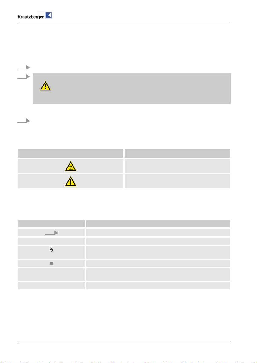
Warning signs Type of danger
Warning – hot surface.
Warning – danger zone.
Additional identifications
The following symbols are used in this manual to highlight operating instructions, results, lists, references, and other elements:
Identification Explanation
Step-by-step instructions
ð
Results of procedural steps
References to sections in this manual and other applicable documents
Lists without specified order
[Pushbuttons] Operating elements (e.g. pushbuttons, switches), display ele-
ments (e.g. signal lights)
‘Display’ Screen elements (e.g. pushbuttons, assignment of function keys)
2.2 Personnel requirements
mail@krautzberger.com, www.krautzberger.com GB–8

Automatic spray gun M -10
ENGLISH
This manual identifies the qualifications of the personnel for the different scopes of work as listed
below:
Qualified personnel
Due to their specialised professional training, knowledge, and experience as well as knowledge of
the industry-specific standards and regulations, qualified personnel are in a position to perform
assigned tasks and to identify and avert potential risks on their own.
Specialised personnel
Due to their specialised professional training, knowledge, and experience as well as knowledge of
the industry-specific standards and regulations, qualified personnel are in a position to perform
assigned tasks and to identify and avert potential hazards on their own.
Trained electrician
Due to specialised professional training, knowledge and experience as well as knowledge of the
industry specific standards and regulations, a trained electrician is able to carry out work on the
electrical systems and to identified and avert potential risks on his/her own.
The trained electrician has completed specialised training for the specific work environment where
he/she works and knows the relevant standards and regulations.
User
The user is familiar with the basic regulations on occupational safety and accident prevention.
2.3 Personal protective equipment
Personal protective equipment is used to protect persons from impacts on their occupational health
and safety.
The personnel must wear personal protective equipment while carrying out the different tasks and
while working with the device.
The selection of the protective equipment depends on the coating material that is used. To
ensure the proper selection of personal protective equipment, the information provided by the
spray material manufacturer indicated on the safety data sheet must be adhered to.
Description of the personal safety equipment recommended by Krautzberger
The personal safety equipment and clothing is described below:
■ 200-0142
GB–9

Protective equipment:
Protective clothing
n
Ear protection
n
Light respiratory protection
n
Safety goggles
n
Protective gloves
n
Safety shoes
n
Safety helmet
n
Operating instructions
T-Dok-213-GB-Rev.2
2.4 Responsibility of the owner
Owner
The owner is the person, who directly operates the machine for commercial or economical purposes or who allows a third-party to use/apply it and who is responsible for the legal product stewardship for the protection of the user, the personnel or third parties.
Owner responsibilities
The machine is used in an industrial environment. The owner of the machine is therefore subject to
the obligations as stipulated by the Occupational Health and Safety Act.
In addition to the safety information in this manual, the country-specific safety, accident prevention
guidelines and environmental protection regulations, applicable at the site of implementation of the
machine must be adhered to.
Furthermore, the owner is responsible for making sure that the machine is always in perfect technical condition. Therefore, the following applies:
n The owner must ensure that the maintenance intervals described in this operating manual are
adhered to.
n The owner must have all safety equipment checked regularly for functionality and complete-
ness.
2.5 Intended use
The spray gun serves to spray paints, colours, adhesives, glazes, enamels, release agents, as
well as other fluids. The nozzle size depends on the spray viscosity of the spray fluid.
The intended use also includes the compliance with all the information in this manual.
2.6 Predictable misuse
Any use beyond the intended use or any other use constitutes misuse.
n Only carry out the installation and start-up in accordance with the steps described in these
operating instructions.
n Always observe the applicable country-specific safety, accident prevention, occupational
safety, and environmental protection regulations for the area of use for the automatic spray
gun.
n Ensure that the utilised hose lines fulfil the requirements with respect to pressure, chemical,
and mechanical loads.
n Do not use sharply abrasive, chemically aggressive, very hot or very cold spray media without
first consulting with and receiving approval from Krautzberger GmbH.
mail@krautzberger.com, www.krautzberger.com GB–10

Automatic spray gun M -10
ENGLISH
n Adhere to the spray media manufacturer's safety data sheets.
n Only use the manufacturer's OEM parts.
n Only operate the automatic spray gun after proper fastening on a suitable carrier design.
n Do not hold the automatic spray gun in your hand during operation.
n Only operate the automatic spray gun while adhering to the values specified in (
Ä
Chapter
12 ‘Technical data’ on page 43).
n Make sure that the connected compressed air is oil-free and free from solid matter.
n Operate the automatic spray gun with processed, dried compressed air (air quality pursuant to
DIN ISO 8573-1: quality class 4).
n Never point the compressed air at living beings.
No claims of any kind can be asserted due to damage resulting from misuse!
2.7 General safety information
WARNING!
Life threatening risk of injury or property damage through the application of hazardous
media!
The application of hazardous media can lead to death, serious injuries or property damage.
– Ensure the resistance of the machine against the medium that is to be applied.
– Always adhere to the safety data sheet of the medium that is to be applied.
WARNING!
Risk of injury through the use of incorrect spare parts!
The use of incorrect or defective spare parts can cause risks for the personnel as well as
damage, malfunctions or complete failure.
– Only use original spare parts from Krautzberger or spare parts that have been approved
by Krautzberger.
– In case of questions, always contact our service department.
CAUTION!
Risk of injury through compressed air!
Uncontrolled leaks of compressed air can lead to serious injuries!
– Prior to any work on the device, all compressed-air lines must be closed and bleed if nec-
essary.
■ 200-0142
GB–11

Operating instructions
T-Dok-213-GB-Rev.2
WARNING!
Sound pressure level
Depending on the operating conditions, the sound pressure of the device may cause hearing
damage.
Take suitable action to reduce the impact of the existing sound pressure level. The owner is
responsible for the type and implementation of suitable measures, which may depend on the
local conditions.
NOTICE!
Property damage due to incorrect installation
Incorrect installation can lead to property damage.
– Check all lines and machines for a tight seat prior to commissioning.
Outdoor operation and operation in exterior areas!
Use suitable measures to protect the device during the operation from environmental impacts
in an exterior area through:
– Moisture
– UV radiation
– Frost, etc.
ENVIRONMENT!
Environmental hazard due to incorrect disposal!
Incorrect disposal may cause environmental hazards.
– After the useful life of the device has been exhausted, dispose of it via the commercial
waste.
– Properly dispose of potential spray fluid residue separately from the device.
– If in doubt, obtain information about environmentally-appropriate disposal with the local
municipalities or specialized disposal companies.
2.8 Residual risks
Devices, machines or systems made by Krautzberger GmbH have been manufactured based on
state-of-the-art technology and in compliance with technical safety regulations.
Nonetheless, their use may pose a threat to the life or health of users or third parties, or harm the
device, the machine, the system or other material assets.
mail@krautzberger.com, www.krautzberger.com GB–12

Automatic spray gun M -10
ENGLISH
n Mechanical hazards (crushing, shearing, cutting, jamming, burning, etc.) are possible at any
time during the installation, during operation as well as during maintenance work and servicing.
2.9 Course of action in an emergency
In principle, the applicable national, regional and internal company regulations concerning the
course of action in case of an emergency must be adhered to and if necessary respective
safety measures must be taken on the system owner's side.
■ 200-0142
GB–13

Operating instructions
T-Dok-213-GB-Rev.2
3 Transport and storage
3.1 Transport
n The automatic spray gun is protected by cardboard packaging.
n The cardboard packaging can be reused for storage.
3.2 Storage of packaged units
Storage of packaged units
Store packaged units subject to following conditions:
n Do not store outside.
n Store in a dry and dust-free environment.
n Keep away from any aggressive media.
n Protect from UV radiation.
n Avoid mechanical shocks.
n Storage temperature: 15 to 40 °C.
n Relative atmospheric humidity: max. 60%.
3.3 Packaging
The spray gun is packaged in accordance with the anticipated transport conditions and the packaging needs to protect it against transport damage, corrosion, and other damage.
n Remove packaging material.
n Remove potentially present transport safety restraints.
mail@krautzberger.com, www.krautzberger.com GB–14
Automatic spray gun M -10
4 Overview
ENGLISH
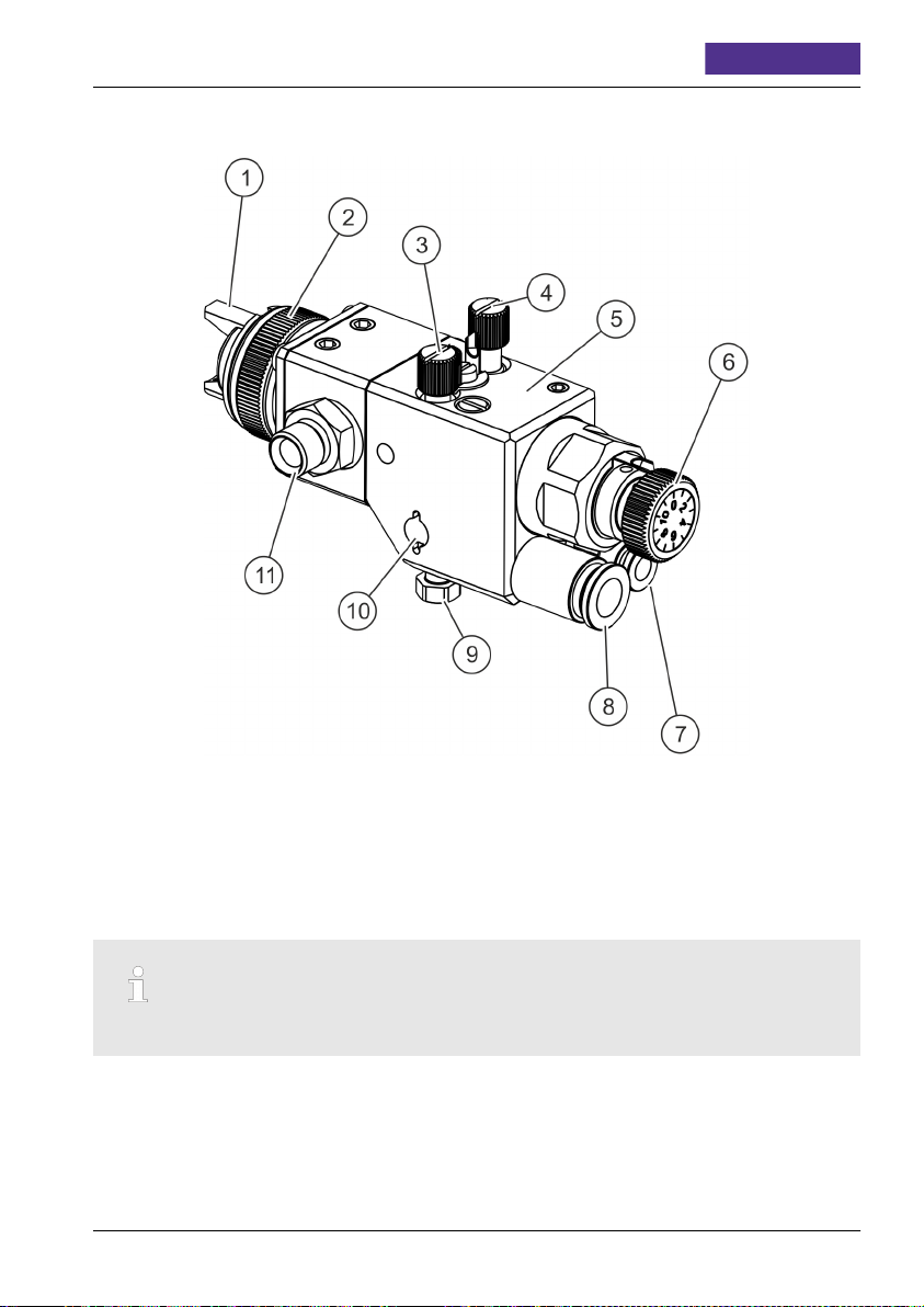
Fig. 1: Overview
1 Air nozzle
2 Knurl nut
3 Flat jet control "F"
4 Round jet control "R"
5 Control section
6 Needle stroke adjustment screw
The connections are marked with letter abbreviations.
■ 200-0142
7 Connection of control air "St"
8 Connection of atomisation air "Z"
9 Installation screw
10 Installation drill hole for retaining bolts
11 Connection of fluid supply "M"
GB–15

Operating instructions
T-Dok-213-GB-Rev.2
5 Installation
5.1 Safety
Personnel:
Specialised personnel
n
Trained electrician
n
Protective equipment:
The selection of the protective equipment depends on the installation conditions on site. Always
observe the applicable country-specific safety, accident prevention, occupational safety, and environmental protection regulations for the proper selection of the protective equipment.
WARNING!
Risk of injury due to improper installation!
Improper installation may cause serious personal injury or material damage.
Note:
– Ensure ample of space for the installation prior to starting any work.
– Carefully handle open, sharp-edged components.
– Maintain order and cleanliness at the installation site. Components that are loosely
stacked or are scattered around can cause accidents.
– Assemble components properly. Adhere to specified screw tightening torque.
– Secure components against tipping or falling.
– Ensure that the utilised hose lines meet the requirements for pressure, chemical and
mechanical loads. At the same time, adhere to the spray media manufacturer's specifica-
tions in the safety data sheet.
CAUTION!
Risk of injury through compressed air!
Uncontrolled leaks of compressed air can lead to serious injuries!
– Prior to any work on the device, all compressed-air lines must be closed and bleed if nec-
essary.
mail@krautzberger.com, www.krautzberger.com GB–16

Automatic spray gun M -10
ENGLISH
CAUTION!
Risk of injury due to sharp edges!
Sharp edges and pointed corners can cause abrasions and cuts on the skin.
Note:
– Proceed cautiously when working on or near sharp edges and pointed corners.
– Wear protective gloves, if in doubt.
5.2 General installation information
Adhere to the following general information for the installation:
n Only carry out the installation and start of operation according to the steps described in this
operating manual.
n Make sure that the utilised hose lines meet the requirements for pressure, chemical and
mechanical loads.
n Only operate the automatic spray gun after proper fastening on a suitable carrier design.
n Make sure that the connected compressed air is oil-free and free of solid matter.
n Operate the automatic spray gun with processed, dried compressed air (air quality pursuant to
DIN ISO 8573-1: grade 4).
n Vibration and recoil forces may occur on the automatic spray gun during operation. Ensure
sufficient fastening.
n Never point the compressed air at living beings.
5.3 Connection scheme
The connection diagram shown here must be seen as an example. Other connection options are
possible depending on the installation situation or the configuration of the automatic spray gun.
■ 200-0142
GB–17

Fig. 2: Connection scheme
Z Atomisation air
St Control air
DV Pressure controller
O/S (E) 3/2 control valve
DE Pressure generator
Operating instructions
M Material
RR Back pressure regulators
RW Agitator unit
F Filter
H Ball cock
T-Dok-213-GB-Rev.2
mail@krautzberger.com, www.krautzberger.com GB–18

Automatic spray gun M -10
ENGLISH
5.4 Mounting the automatic spray guns
Changing the installation position of the spray gun
The automatic spray gun can be mounted on both sides on the retaining bolts in order to
change the installation position.
Fig. 3: Mounting the automatic spray guns
1. Slide the automatic spray gun ( Fig. 3/1) with the respectively designed drill hole over the
retaining bolt ( Fig. 3/3).
2. Fix retaining bolt with installation screws ( Fig. 3/2).
3. Ensure proper earth connection of the automatic spray gun.
5.5 Connecting the automatic spray gun
See also ( Ä Chapter 5.3 ‘Connection scheme’ on page 17).
WARNING!
Danger of injury due to improper connection!
When the fluid supply is pressurised, e.g. from pressure containers or with pumps, the range
of the fluid jet can increase by a multiple in case of atomisation air failure. This presents a
hazard to people and property.
– Make sure that the fluid supply and the control air are interrupted if the atomisation air
pressure drops off quickly.
– It is recommended to regulate the atomisation air pressure via a filter pressure reducer.
■ 200-0142
GB–19

Operating instructions
The connections for control and atomisation air are marked with letter abbreviations.
Fig. 4: Connecting the automatic spray gun
1. Connect the control air to input "St" ( Fig. 4/1).
2. Connect the atomisation air to input "Z" ( Fig. 4/2).
3. Connect the fluid line to ( Fig. 4/3).
T-Dok-213-GB-Rev.2
mail@krautzberger.com, www.krautzberger.com GB–20

Automatic spray gun M -10
ENGLISH
6 Operation
6.1 Safety
Personnel:
User
n
Specialised personnel
n
Protective equipment:
The selection of the personal protective equipment depends on the utilised medium of the system
owner. The information provided by the medium manufacturer indicated on the safety data sheet
must be adhered to in order to ensure the proper selection of personal protective equipment.
WARNING!
Risk of injury due to improper operation!
Improper operation can lead to serious personal injuries or property damage.
Note:
– Never point compressed air at people.
– Check the material and compressed air hose lines before each use for damage and tight
fit.
– Adhere to the spray media manufacturer's specifications in the safety data sheet.
– Make sure that the connected compressed air is oil-free and free of solid matter.
WARNING!
Risk of death, risk of injury or property damage due to hazardous media!
Potential consequences: The application of hazardous media can lead to death, severe injuries or property damage.
When handling hazardous substances, ensure that the current safety data sheets of the hazardous substance manufacturer are available. The necessary measures can be derived from
the content of the safety data sheet. Since the hazardous potential of a material can be reassessed at any time due to lessons learned, the safety data sheet must be checked regularly
and replaced if necessary.
The system owner is responsible for the presence and the up-to-date status of the safety data
sheet and the associated generation of the risk assessment of the effected workstations.
■ 200-0142
GB–21

Operating instructions
T-Dok-213-GB-Rev.2
WARNING!
Hazardous media / contamination of persons and equipment
Possible consequences: Fatality or serious injuries, property damage
– Ensure the resistance of the device against the medium that is to be conveyed
– Always adhere to the safety data sheet of the medium that is to be conveyed The system
owner is responsible that the safety data sheet is present and up-to-date
– The safety data sheet of the conveyed medium is always authoritative for the initiation of
countermeasures in case of a leak of the conveyed medium
– Adhere to the general limitations with respect to viscosity limits, chemical stability and
density
CAUTION!
Risk of injury through compressed air!
Uncontrolled leaks of compressed air can lead to serious injuries!
– Prior to any work on the device, all compressed-air lines must be closed and bleed if nec-
essary.
WARNING!
Risk of fatal injury, risk of injury or property damage due to damaged or disconnected
lines!
Damaged or disconnected lines can cause death, serious injuries or property damage due to
whip-like movements and the spraying of fluids.
Note:
– Check the fluid and compressed air lines for damage and a tight fit prior to every work
process.
WARNING!
Risk of injury due to hot surfaces!
The surfaces of components can become very hot during operation. Direct contact with hot
surfaces causes severe skin burns.
– Do no touch hot surfaces during operation, wear protective gloves if necessary.
– Ensure that all surfaces have sufficiently cooled down prior to starting any work.
mail@krautzberger.com, www.krautzberger.com GB–22

Automatic spray gun M -10
WARNING!
Hearing damage due to excessive noise exposure!
Depending on the operating conditions, the sound pressure of the device/machine may cause
hearing damage.
Note:
– Take suitable action to reduce the impact of the existing sound pressure level. The owner
is responsible for the type and implementation of suitable measures, which may depend
on the local conditions.
ENGLISH
6.2 General information about the start-up
Adhere to the following general information for the start-up:
n Only carry out the commissioning of the automatic spray gun pursuant to the steps described
in these operating instructions.
n Check the material and compressed air hose lines for damage and tight fit before each use.
n Always observe the applicable country-specific safety, accident prevention, occupational
safety, and environmental protection regulations for the area of use for the automatic spray
gun.
n Do not use sharply abrasive, chemically aggressive, very hot or very cold spray media without
first consulting with and receiving approval from Krautzberger GmbH.
n Adhere to the spray media manufacturer's safety data sheets.
n Only operate the automatic spray gun while adhering to the values specified in (
12 ‘Technical data’ on page 43).
n Only operate the automatic spray gun after proper fastening on a suitable carrier design.
n Do not hold the automatic spray gun in your hand during operation.
n Never point the compressed air at living beings.
n Adhere to the operating manuals for the respective components
Ä
Chapter
6.3 Shutting down
6.3.1 Temporary shut-down
End the spray procedure by switching off the control air (connection "St").
The atomiser air (connection "Z") is automatically closed in the automatic spray gun.
6.3.2 Long-term shut-down
1.
Close the air supply for control air and atomiser air (
on page 17).
2. Close the material supply and switch off the pump if necessary.
3.
If necessary, clean the spray gun ( Ä Chapter 7.3 ‘Cleaning’ on page 27).
■ 200-0142
Ä
Chapter 5.3 ‘Connection scheme’
GB–23

Operating instructions
T-Dok-213-GB-Rev.2
6.4 Start of operation
1. Switch on the compressed air supply.
2. Where applicable, switch on pump or pressure container for spray fluid.
3. Point automatic spray gun at a test surface.
4. Start spraying process by switching on the control air.
5.
Adjust the spray pattern ( Ä Chapter 6.5 ‘Adjusting the spray pattern’ on page 24).
6. Complete the spraying process by switching off the control air.
7. Direct spray gun towards workpiece.
8. Start spraying process by switching on the control air.
6.5 Adjusting the spray pattern
Air and fluid nozzles are available in various sizes. There are 4 different families:
n Round jet – cone-shaped jet in front of the nozzle.
n Flat jet – width-adjustable jet for flat-shaped application.
n Rotary stream – a rotary pulse produces a highly “swirled” spray jet; for difficult workpiece
geometries (angular sections etc.).
n Full-cone rotary stream – a rotary pulse produces a highly “swirled” spray jet; for difficult
workpiece geometries (back cuts, etc.).
Adjust the spray pattern with the following measures:
n Change the atomiser air pressure.
n Change the pressure of the spray fluid.
n Select another nozzle size.
n Adjusting the needle stroke (
Ä
Chapter 6.6 ‘Adjusting the needle stroke’ on page 25).
Too-high air pressure causes unnecessarily high air consumption and too-strong atomisation
of the spray fluid. It is recommended that you first adjust the spray pattern by varying the air
and spray fluid pressure. If you cannot achieve satisfactory results this way, you should
experiment with other nozzle sizes.
mail@krautzberger.com, www.krautzberger.com GB–24

Automatic spray gun M -10
ENGLISH
6.6 Adjusting the needle stroke
Fig. 5: Adjusting the needle stroke
1. Pull out the needle stroke adjustment screw ( Fig. 5/1) until it loosens.
2. Adjust the needle stroke by turning the needle stroke adjustment screw ( Fig. 5/1).
3. Push in the needle stroke adjustment screw ( Fig. 5/1) until it tightens again.
■ 200-0142
GB–25

Operating instructions
T-Dok-213-GB-Rev.2
7 Maintenance
7.1 Safety
Personnel:
Specialised personnel
n
Protective equipment:
The selection of the protective equipment depends on the maintenance conditions on site and the
medium utilized by the operating company. The applicable country-specific safety, accident prevention, occupational safety, and environmental protection regulations must adhered to for the
proper selection of the protective equipment and the information given by the spray media manufacturer on the safety data sheet must be taken into consideration.
WARNING!
Risk of injury through the use of incorrect spare parts!
The use of incorrect or defective spare parts can cause risks for the personnel as well as
damage, malfunctions or complete failure.
– Only use original spare parts from Krautzberger or spare parts that have been approved
by Krautzberger.
– In case of questions, always contact our service department.
CAUTION!
Risk of injury through compressed air!
Uncontrolled leaks of compressed air can lead to serious injuries!
– Prior to any work on the device, all compressed-air lines must be closed and bleed if nec-
essary.
CAUTION!
Risk of injury due to sharp edges!
Sharp edges and pointed corners can cause abrasions and cuts on the skin.
Note:
– Proceed cautiously when working on or near sharp edges and pointed corners.
– Wear protective gloves, if in doubt.
mail@krautzberger.com, www.krautzberger.com GB–26

Automatic spray gun M -10
ENGLISH
7.2 Maintenance schedule
The following sections describe the maintenance work that is required for optimal and fault-free
operation of the device. Check wearing parts such as seals, nozzles, and needles at regular intervals. The level of wear depends on the abrasiveness of the spray fluid used. Escaping air and
spray fluid as well as the deterioration of the spray pattern are signs that parts are worn. In case of
questions about maintenance work and intervals, contact the manufacturer; see contact information on the last page.
Interval Maintenance work Personnel
Before performing any
maintenance work
if needed
Clean automatic spray gun ( Ä Chapter 7.3
‘Cleaning’ on page 27)
Change fluid and air nozzle ( Ä Chapter 7.4
Qualified personnel
Qualified personnel
‘Changing the air and fluid nozzles’ on page 29)
Change fluid needle ( Ä Chapter 7.5 ‘Changing
Qualified personnel
the fluid needle’ on page 29)
Change needle seals ( Ä Chapter 7.5
Qualified personnel
‘Changing the fluid needle’ on page 29)
7.3 Cleaning
WARNING!
Risk of injury due to improper cleaning!
– Adhere to the safety data sheets of the cleaning product manufacturer.
– Do not immerse the automatic spray gun entirely in cleaning product.
■ 200-0142
GB–27

Operating instructions
1.
Interrupt the operation ( Ä Chapter 6.3 ‘Shutting down’ on page 23).
T-Dok-213-GB-Rev.2
2. Switch off the system and secure it against being switched on again.
3. Connect cleaning product to material supply connection "M".
4. Switch on the compressed air supply.
5. Where applicable, switch on pump or pressure container for detergent.
6. Begin the spraying procedure by switching on the control air (connection "ST").
7. Spray until the cleaning product runs clear.
8. Interrupt the supply of cleaning product by switching off the pump or the pressure container.
9. Blow out cleaning product residue by briefly switching on the control air.
10. Switch off the compressed air supply and secure it against a restart.
11. Clean the outside of the device with a cloth dipped in cleaning product.
12.
Remove fluid and air nozzle ( Ä Chapter 7.4 ‘Changing the air and fluid nozzles’
on page 29) and clean with a soft brush. Do not use hard or sharp-edged objects. We rec-
ommend our brush set. Therefore please contact our Customer Care department.
13. Lightly grease sliding parts. We recommend the Krautzberger special grease. Therefore
please contact our Customer Care department.
mail@krautzberger.com, www.krautzberger.com GB–28

Automatic spray gun M -10
7.4 Changing the air and fluid nozzles
Removing the nozzles
1.
Clean automatic spray gun ( Ä Chapter 7.3 ‘Cleaning’ on page 27).
Fig. 6: Removing the nozzles
2. Dismantle circlip ( Fig. 6/4) using suitable tools.
3. Loosen the knurl nut ( Fig. 63).
4. Remove the air nozzle ( Fig. 6/2).
5. Unscrew the fluid nozzle ( Fig. 6/1) with a fork wrench.
ENGLISH
Always change the fluid nozzle and needle together ( Ä Chapter 7.5 ‘Changing the
fluid needle’ on page 29).
Attaching the nozzles
1. Tighten the fluid nozzle ( Fig. 6/1) with a fork wrench.
2. Attach the air nozzle ( Fig. 6/2) and tighten it with the knurl nut ( Fig. 6/3).
3. Insert circlip ( Fig. 6/4) using suitable tools.
7.5 Changing the fluid needle
– Always change the fluid nozzle and needle together ( Ä Chapter 7.4 ‘Changing the air
and fluid nozzles’ on page 29).
– Lightly grease sliding parts. Use special grease of Krautzberger (contact data see last
page).
■ 200-0142
GB–29

Operating instructions
1.
Clean automatic spray guns ( Ä Chapter 7.3 ‘Cleaning’ on page 27).
T-Dok-213-GB-Rev.2
Fig. 7: Remove the fluid needle
2. Use fork wrench to loosen and screw valve seal ( Fig. 7/8) out of control section ( Fig. 7/1).
WARNING!
The valve seal ( Fig. 7/8) is under spring tension.
3. Remove the compression spring ( Fig. 7/7).
4. Carefully pull piston ( Fig. 7/6) with needle ( Fig. 7/5) out of the control section ( Fig. 7/1).
5. Take separating disk ( Fig. 7/4) out of control section ( Fig. 7/1) and check condition of O-
rings ( Fig. 7/2 and 3). If necessary, remove O-rings ( Fig. 7/2 and 3).
Fig. 8: Remove the fluid needle
6. Loosen closure ( Fig. 8/4), fasten piston ( Fig. 8/2) with a fork wrench.
7. Remove closure ( Fig. 8/4) and spring ( Fig. 8/3).
mail@krautzberger.com, www.krautzberger.com GB–30

Automatic spray gun M -10
Fig. 9: Remove the fluid needle
8. Carefully pull needle ( Fig. 9/2) out of piston ( Fig. 9/1).
ENGLISH
■ 200-0142
GB–31

Operating instructions
T-Dok-213-GB-Rev.2
Installing the fluid needle
Fig. 10: Needle dimension
1. The needle dimension of 72.5 mm is pre-set and should not be changed ( Fig. 10/1).
Fig. 11: Installing the fluid needle
2. Carefully insert needle ( Fig. 11/2) in piston ( Fig. 11/1).
Fig. 12: Installing the fluid needle
3. Check the condition of the seals ( Fig. 12/1 and 3), replace if necessary.
4. Insert the spring ( Fig. 12/2) and tighten the closure ( Fig. 12/4). Fasten piston with fork
wrench.
Fig. 13: Installing the fluid needle
5. If necessary, insert O-rings ( Fig. 13/2 and 3) and insert separating disk ( Fig. 13/4) in control section (/1).
mail@krautzberger.com, www.krautzberger.com GB–32

Automatic spray gun M -10
ENGLISH
6. Carefully push piston ( Fig. 13/6) with needle ( Fig. 13/5) into the control section (
Fig. 13/1).
7. Insert compression spring ( Fig. 13/7).
8. Screw valve seal ( Fig. 13/8) into control section ( Fig. 13/1) and tighten with fork wrench.
7.6 Changing needle seals
Lightly grease sliding parts. Use special grease of Krautzberger (contact data see last page).
■ 200-0142
GB–33

Operating instructions
T-Dok-213-GB-Rev.2
Removing needle seals
1.
Clean automatic spray guns ( Ä Chapter 7.3 ‘Cleaning’ on page 27).
2.
Screw off knurl nut ( Ä Chapter 7.4 ‘Changing the air and fluid nozzles’ on page 29)
Fig. 14: Removing needle seals
3. Loosen fastening screws ( Fig. 14/8) of the head section ( Fig. 14/7) and remove head section.
4. Pull needle guide ( Fig. 14/4) out of control section.
If the needle guide is lodged tight, dismantle the fluid needle ( Ä Chapter 7.5
‘Changing the fluid needle’ on page 29) and carefully push the needle guide out.
5. Remove the slotted rings ( Fig. 14/1, 2 and 5).
6. Check the condition of the O-rings ( Fig. 14/3 and 6), and replace if necessary.
mail@krautzberger.com, www.krautzberger.com GB–34

Automatic spray gun M -10
ENGLISH
Inserting the needle seals
Fig. 15: Installation position
1. Insert the slotted rings ( Fig. 15/1, 2 and 3) into the needle guide. During this process,
ensure the correct position of the slotted rings ( Fig. 15/1, 2 and 3).
Fig. 16: Inserting the needle seals
2. If necessary, insert O-rings ( Fig. 16/1 and 3).
3. Carefully insert needle guide ( Fig. 16/2) into the control section.
Ä
Necessary, install the fluid needle (
Chapter 7.5 ‘Changing the fluid needle’
on page 29).
Tighten head section ( Fig. 16/4) with fastening screws ( Fig. 16/5).
4.
5.
Screw on knurl nut ( Ä Chapter 7.4 ‘Changing the air and fluid nozzles’ on page 29)
■ 200-0142
GB–35

Operating instructions
T-Dok-213-GB-Rev.2
8 Troubleshooting
Personnel:
Qualified personnel
n
If the fault is not included in the following table or if it cannot be eliminated with the measures
described, contact Customer Care.
Protective equipment:
The selection of the personal protective equipment depends on the utilised medium of the system
owner. The information provided by the medium manufacturer indicated on the safety data sheet
must be adhered to in order to ensure the proper selection of personal protective equipment.
Spray pattern Error Cause Remedy
Normal flat jet spray pattern
Spray pattern too
heavy towards the top
and towards the
bottom
Spray pattern concentrated on the left or
right side
Heavy application in
the centre of the spray
pattern
n Dirty air nozzle
n Dirty fluid nozzle
n Dirty air nozzle
n Dirty fluid nozzle
n Too much mate-
rial
Clean nozzles (
Ä
Chapter 7.3
‘Cleaning’ on page 27)
Clean nozzles (
Ä
Chapter 7.3
‘Cleaning’ on page 27)
n Reduce material
supply
n Material too thick n Thin material
mail@krautzberger.com, www.krautzberger.com GB–36

Automatic spray gun M -10
Spray pattern Error Cause Remedy
Split spray pattern
n Insufficient mate-
rial
n Flat jet air pres-
sure too high
n Increase material
supply
n Reduce flat jet air
pressure
ENGLISH
Spray pattern too thin
Fluid jet comes out in
spurts or rapid bursts
Leakage on the
clamping screw
Fluid nozzle drips
n Knurled nut loose
n Insufficient mate-
rial supply
Tighten knurled nut
n Increase material
supply
n Blocked fluid path n Clean
n Loose or dam-
aged fluid nozzle
n Tighten or replace
( Ä Chapter 7.4
‘Changing the air
and fluid nozzles’
on page 29)
n Worn needle seal n Replace needle
seal ( Ä Chapter
7.6 ‘Changing
needle seals’
on page 33)
n Needle seal
defective
n Replace needle
seal ( Ä Chapter
7.6 ‘Changing
needle seals’
on page 33)
n Worn or damaged
fluid needle
n Change fluid
needle (
Ä
Chapter 7.5
‘Changing the
fluid needle’
on page 29)
■ 200-0142
GB–37

Operating instructions
Spray pattern Error Cause Remedy
n Dirty or damaged
fluid nozzle
n Clean (
Ä
‘Cleaning’
on page 27) or
replace fluid
nozzle (
Ä
‘Changing the air
and fluid nozzles’
on page 29)
- Spray pattern change
after reassembly.
Atomisers for round
n Air distributor ring
installed wrong
way
n Remove air dis-
tributor ring and
install correctly
and flat jets can no
longer be regulated
separately
8.1 Customer Care
Krautzberger GmbH
Customer service
Stockbornstr. 13
65343 Eltville am Rhein
+49 6123 - 698151
customercare@krautzberger.com
T-Dok-213-GB-Rev.2
Chapter 7.3
Chapter 7.4
mail@krautzberger.com, www.krautzberger.com GB–38

Automatic spray gun M -10
9 Spare parts
– Only use OEM parts from Krautzberger or Krautzberger-approved spare parts.
– In case of questions, always contact our Customer Care department.
Spare parts order – General
To make spare part ordering easier, please provide the following information:
– Serial number
– Model / product name
– Designation
– Item number according to spare parts list
– Quantity
– Desired shipping method (post, freight, sea, air, express)
– Delivery address
9.1 Spare parts
ENGLISH
A complete spare part overview is available on the website of Krautzberger GmbH:
www.krautzberger.de
■ 200-0142
GB–39

Operating instructions
T-Dok-213-GB-Rev.2
10 Accessories
A wide range of accessories are available for the automatic spray gun. For further information, visit
us on the Internet (www.krautzberger.com) or contact your Krautzberger specialist dealer, consultant or our office staff.
Here are a few examples:
n Nozzle extensions
– Nozzle extensions are particularly well-suited for use when coating cavities, e.g. pipes,
canisters, tins or other hard-to-access containers. Nozzle extensions come in a variety of
standard models. The length, form, and spray angle extensions can be adjusted to customer-specific requirements.
n Seals
– Seals, bats touch the coating material, can be made of stainless steel, copper, fibre,
leather, PA, PE or PTFE.
n Stainless steel model
– Head section made of stainless steel, during the processing of particularly acidic or alka-
line coating material
n Filter
– Filter with mesh sizes of 0.06 - 0.3 mm which prevent the clogging of the fluid nozzle
n Quick, angle and swivel fittings
– to connect the fluid hose
n Circulation connection
– for coating materials that have a tendency to clog and which must be kept in circulation
n etc.
mail@krautzberger.com, www.krautzberger.com GB–40

Automatic spray gun M -10
ENGLISH
11 Disassembly and disposal
11.1 Safety
Personnel:
Qualified personnel
n
Protective equipment:
The selection of the protective equipment depends on the installation conditions on site and the
medium utilized by the operating company. The applicable country-specific safety, accident prevention, occupational safety, and environmental protection regulations must adhered to for the
proper selection of the protective equipment and the information given by the spray media manufacturer on the safety data sheet must be taken into consideration.
WARNING!
Risk of injury due to improper disassembly!
Residual stored energies, component edges, points and corners on or in the device or on the
required tools may cause injuries.
– Make sure you have sufficient space before starting the work.
– Carefully handle open, sharp edged components.
– Keep the workplace orderly and clean! Loosely stacked or scattered components and
tools are sources for accidents.
– Properly dismantle components. Pay attention to very high individual weight of some of
the components. If necessary, use hoisting equipment.
– Secure components so that they cannot fall or tip over.
– If questions arise, consult with the customer service from Krautzberger.
11.2 Disassembly
Prior to starting the disassembly:
n Switch off the device and secure it against restart.
n Physically disconnect the entire power supply from the device, and discharge any energy
stored in the machine.
n Remove and dispose of operating and auxiliary material as well as remaining processing
materials in an environmentally friendly manner.
Afterwards, properly clean components and modules and take them apart in compliance with applicable local occupational health & safety regulations as well as environmental protection regulations.
11.3 Disposal
If no return or disposal agreement has been made, recycle the dismantled parts:
n Scrap metals.
n Recycle plastic components.
■ 200-0142
GB–41

Operating instructions
T-Dok-213-GB-Rev.2
n Sort remaining components based on the respective material and dispose of them accord-
ingly.
n Properly dispose of potential spray fluid residue separately from the device.
If in doubt, obtain information about environmentally-appropriate disposal with the local municipalities or specialised disposal companies.
mail@krautzberger.com, www.krautzberger.com GB–42

Automatic spray gun M -10
ENGLISH
12 Technical data
12.1 Dimensions and weight
Specification Value Unit
Width min. 46 mm
Height 60 mm
Length 117 mm
Connection of spray fluid G1/8 "
Connection atomiser air (plastic hose - recommended interior diameter for 4 m length)
Connection control air (plastic hose - recommended interior diameter for 4 m length)
Weight approx. 380 g
12.2 General specifications
Specification Value Unit
Fluid pressure max. 1.2 / 12 MPa / bar
Material temperature max. +100 °C
Sound exposure (depending on nozzle) 73 - 96 db(A)
Control air pressure max. 0.4 - 0.8 / 4 - 8 MPa / bar
Control and atomiser air temperature max. +50 °C
Atomiser air pressure max. 0.8 / 8 MPa / bar
3/5 mm
3/5 mm
■ 200-0142
GB–43

12.3 Dimensions
Operating instructions
T-Dok-213-GB-Rev.2
Fig. 17: Dimensions
mail@krautzberger.com, www.krautzberger.com GB–44

Automatic spray gun M -10
13 Declaration of incorporation
ENGLISH
Fig. 18: Declaration of incorporation
■ 200-0142
GB–45

Operating instructions
T-Dok-213-GB-Rev.2
14 Notes
______________________________________________________________________________
______________________________________________________________________________
______________________________________________________________________________
______________________________________________________________________________
______________________________________________________________________________
______________________________________________________________________________
______________________________________________________________________________
______________________________________________________________________________
______________________________________________________________________________
______________________________________________________________________________
______________________________________________________________________________
______________________________________________________________________________
______________________________________________________________________________
______________________________________________________________________________
______________________________________________________________________________
______________________________________________________________________________
______________________________________________________________________________
______________________________________________________________________________
______________________________________________________________________________
______________________________________________________________________________
______________________________________________________________________________
______________________________________________________________________________
______________________________________________________________________________
______________________________________________________________________________
______________________________________________________________________________
______________________________________________________________________________
______________________________________________________________________________
______________________________________________________________________________
______________________________________________________________________________
______________________________________________________________________________
______________________________________________________________________________
mail@krautzberger.com, www.krautzberger.com GB–46

Automatic spray gun M -10
ENGLISH
15 Index
C
Cleaning ......................................................27
Connection values ................................................43
Customer Care ..................................................38
D
Delivery ......................................................14
Dimensions ....................................................43
Disassembly ...................................................41
Disposal ......................................................41
H
Health .......................................................11
M
Measurements ..................................................44
O
Overview .....................................................15
Owner .......................................................10
P
Personal protective equipment .........................................9
Personnel ......................................................8
Protective equipment ...............................................9
S
Storage ......................................................14
Symbols
in this manual .................................................7
T
Troubleshooting table ..............................................36
U
User qualification .................................................8
W
Weight .......................................................43
■ 200-0142
GB–47


Krautzberger GmbH
Stockbornstrasse 13
65343 Eltville am Rhein, Germany
Hotline: +49 (0) 6123 698-222
Reception: +49 (0) 6123 698-0
Fax: +49 (0) 6123 698-200
Email: mail@krautzberger.com
Internet: www.krautzberger.com
© Krautzberger GmbH 2017
© Krautzberger GmbH 2017
 Loading...