

Kraus Optima Owner's Manual

OptimaTM Dispenser
Owner’s Manual
Winnipeg, Manitoba, Canada
Kraus Global, Ltd.
25 Paquin Rd.
R2J 3V9
Ph. 204-663-3601
©2014 Kraus Global Ltd.
Retail CNG Dispenser Manual i
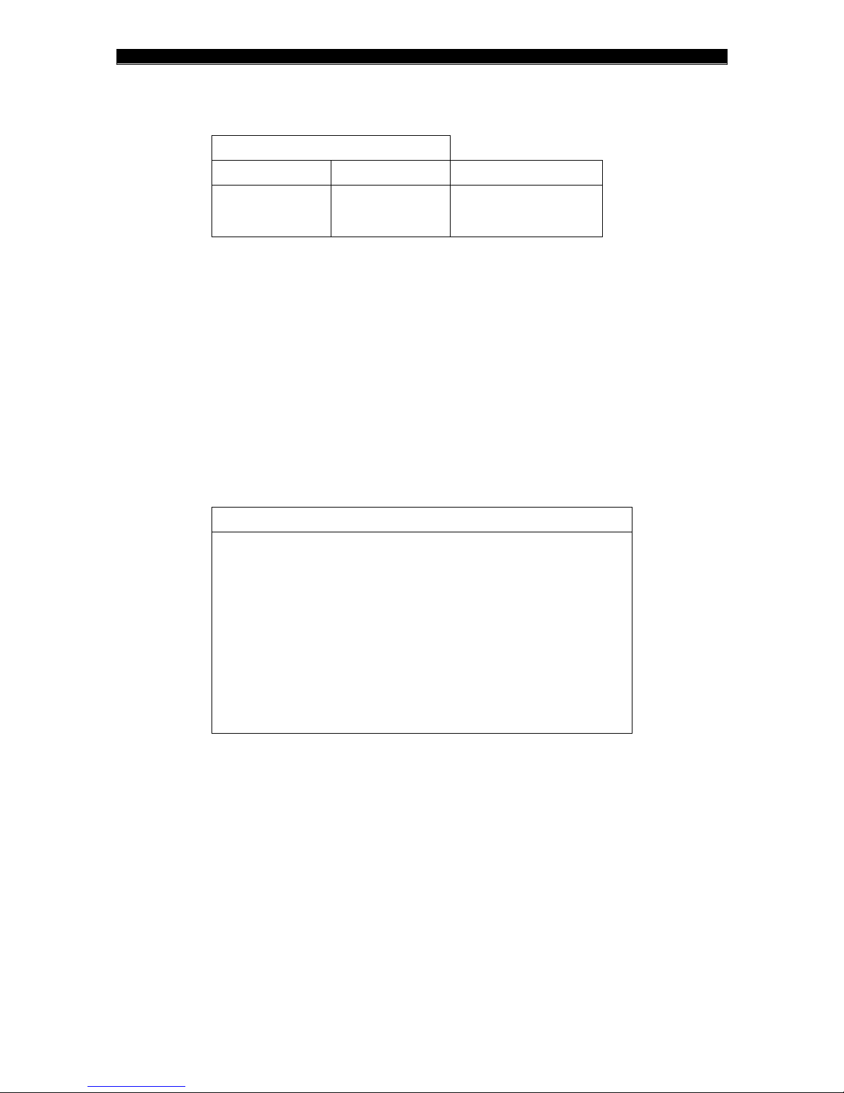
REVISION HISTORY
Document No. RFD.020.MNL.00
Revision #
Date
Description
02
June 2017
Editorial updates and
corrections, Production
release.
North America
American Society of Mechanical Engineers (ASME) Boiler and
Pressure Code
American Society of Mechanical Engineers (ASME) B31.3 – Process
Piping
Canadian Gas Association (CGA) B108 NGV Refueling Stations
Installation Code
Canadian Standards Association (CSA) C22.1 Canadian Electrical
Code (CEC) Part I
National Fire Protection Association (NFPA) 52 Standard for
Compressed Natural Gas (CNG) Vehicular Fuel Systems
National Fire Protection Association (NFPA) 70 National Electrical
Code
Document revision history
Code compliance
Kraus CNG dispensers are manufactured to comply with the following codes and standards:

CONTENTS
CONTENTS
1. INTRODUCTION 1
1.1 About this manual 1
1.2 Additional references 2
1.3 Contact information 2
1.4 Warnings and notifications 3
1.5 Warranty information 3
1.6 The Retail CNG Optima™ dispenser 4
1.7 Dispenser theory of operation 4
1.7.1 MICON NEXTGEN 1.0® 4
1.7.2 Buffer storage systems 5
1.7.3 Cascade storage systems 5
1.7.4 The Retail unit layout 6
2. SAFETY 7
2.1 General safety 7
2.2 Filling safety 8
2.3 Dispenser hose safety 9
2.4 Maintenance safety 10
2.5 Leak test safety 11
3. INSTALLATION AND SETUP 12
3.1 Installation guidelines 12
3.2 Pre-installation 14
3.2.1 Site preparation 14
3.2.2 Uncrating the dispenser 15
3.2.3 Lifting and anchoring the dispenser 16
3.3 Installation 17
3.3.1 Electrical and communication connections 17
3.3.2 Pressure line connection 17
3.3.3 Filters 18
3.3.4 Attaching the hose 21
3.4 Startup procedures 23
3.4.1 Powering the dispenser 23
3.4.2 Pressurizing the dispenser 24
3.4.3 Connecting the Manager-keypad 25
3.4.4 Enabling 2-wire mode and setting pump/hose IDs 27
3.4.5 Configuring the POS System 28
3.4.6 Commissioning 29
4. OPERATION AND MAINTENANCE 30
©2014 Kraus Global Ltd.
Retail CNG Dispenser Manual iii

CONTENTS
4.1 Filling procedure 30
4.2 Programming the MICON® 31
4.2.1 Manager Menu/Programming mode 31
4.2.2 Disabling Programming mode 33
4.3 Dispenser maintenance 35
4.3.1 General dispenser maintenance guidelines 35
4.3.2 Dispenser venting procedure 36
4.3.3 Leak monitoring 37
4.4 Component maintenance 38
4.4.1 MICON® mainboard 38
4.4.2 KAF 402™ solenoid inlet valve 39
4.4.3 Inline filters 39
4.4.4 Air purge system 40
5. TROUBLESHOOTING 41
5.1 MICON® fault codes 41
5.2 System fault codes 45
5.3 Dispenser issues 45
5.3.1 Voltage statuses 49
APPENDIX 1
A.1 Component descriptions and specifications 1
Air purge system components 1
Power supply 5
Air purge system/authorization relay 5
Micro Motion® CNG050 flow meter 6
KAF 402™ solenoid inlet valve 8
Fueling nozzles 9
A.2 Maintenance task list 10
GLOSSARY 1
INDEX 1
©2014 Kraus Global Ltd.
iv Retail CNG Dispenser Manual

CONTENTS
This page intentionally left blank
©2014 Kraus Global Ltd.
Retail CNG Dispenser Manual v

CONTENTS
This page intentionally left blank
©2014 Kraus Global Ltd.
vi Retail CNG Dispenser Manual

CONTENTS
DISCLAIMER
This manual and the information contained herein are not intended to provide
you with any advice on product design, filling station specifications, installation of
equipment, or similar matters and should not be relied upon for such purposes.
Neither Kraus Global Ltd. nor any of its employees or agents are your
professional advisers. You should assess whether you require such advisers and
additional information and, where appropriate, seek independent professional
advice. Kraus, its subsidiaries and affiliates, are not responsible in any manner
for direct, indirect, special or consequential damages however caused arising
from your use of this manual and the information contained herein.
©2014 Kraus Global Ltd.
Retail CNG Dispenser Manual vii


1. INTRODUCTION
1. INTRODUCTION
1.1 About this manual
Purpose
This manual is designed to provide installation, operation, and
maintenance guidelines and procedures for Kraus’ Retail
compressed natural gas (CNG) Optima™ dispensers.
Intended users
This manual is designed to be clear, comprehensive, and available to
anyone installing, maintaining, or overseeing the operation of Kraus’
Retail CNG Optima™ dispensers.
Scope
This manual is divided into five chapters:
1. INTRODUCTION
This chapter provides general information about this manual and
the Retail CNG Optima™ dispenser.
2. SAFETY
This chapter provides general installation, operation, and
maintenance safety guidelines.
3. INSTALLATION AND SETUP
This chapter provides installation and configuration guidelines
and procedures for the Retail CNG Optima™ dispenser.
4. OPERATION AND MAINTENANCE
This chapter provides operation and maintenance guidelines and
procedures for the Retail CNG Optima™ dispenser.
5. TROUBLESHOOTING
This chapter provides general troubleshooting guidelines for
possible installation, operation, and maintenance issues.
©2014 Kraus Global Ltd.
Retail CNG Dispenser Manual 1

1. INTRODUCTION
Kraus Global Ltd.
25 Paquin Road
Winnipeg, Manitoba
Canada, R2J 3V9
www.krausglobal.com
Phone: 204-663-3601
Fax: 204-663-7112
Extensions:
Engineering
203 / 276
Logistics
215
Technical Support
212
Sales
235
1.2 Additional references
In addition to this manual, the following document is also provided
with each dispenser package:
Quick-Start Guide—Optima™ CNG Dispenser (RFD.010)
The following documents are available on request:
MICON NEXTGEN 1.0
Hazardous Locations Control Drawing (MNG0002.MNL)
Engineering package
o Flow schematic
o Electrical schematic
o Construction drawings
Final inspection checklist
Quality control notices
Quality control information packages
®
Owner’s Manual (MNG0001.MNL)
If you are missing any of the documents listed above or require
additional assistance at any time, please contact Technical Support.
1.3 Contact information
©2014 Kraus Global Ltd.
2 Retail CNG Dispenser Manual

1. INTRODUCTION
ADVICE
This indicator provides helpful tips and other advice on proper equipment
installation, usage, and maintenance.
ATTENTION
This indicator provides important notifications about the dispenser and its
components.
CAUTION
This indicator provides critical warnings that may help prevent human
injury and equipment damage.
1.4 Warnings and notifications
The following indicators provide various warnings and notifications
throughout this manual:
1.5 Warranty information
For questions or concerns regarding dispenser-warranty policies,
please contact Sales.
©2014 Kraus Global Ltd.
Retail CNG Dispenser Manual 3

1. INTRODUCTION
Dispenser model
Retail CNG Optima™ Dispenser
Storage system
Buffer (1 large bank) or Cascade (up to 3 banks)
Filling system
High-flow or Standard-flow or Split-flow
Filling pressure
P30 or P36 or Split-pressure
Hose configuration
Single or Dual
1.6 The Retail CNG Optima™ dispenser
The Retail CNG Optima™ dispenser is available in a single or
multiple-line configuration. Each configuration is available in
standard, high or split-flow systems; P30, P36, or split-pressure;
single or dual hose setup; and buffer or cascade sequencing.
Additionally, the Retail CNG dispenser incorporates an industryleading retail design that includes an embedded card reader, keypad,
receipt printer, full-color display and secondary display. Table 1.1
below describes these customizable features.
Table 1.1: Retail dispenser configurations
1.7 Dispenser theory of operation
This section explains how Kraus’ MICON NEXTGEN 1.0® pump-
controller and KAF 402™ solenoid valves operate to control gas flow
within CNG dispensers.
1.7.1 MICON NEXTGEN 1.0®
Kraus’ MICON NEXTGEN 1.0® pump-controller is an inexpensive
alternative to using PLC units for operating fuel dispensers. For CNG
dispensers, the MICON® takes readings from the mass flow meter,
pressure transducer, and temperature probe to determine a final fill
pressure that is based on a series of algorithms in accordance with
the Ideal Gas Law, “PV = nRT”. The result is a controlled fill of a
vehicle’s CNG tank to a safe maximum limit.
After the fueling nozzle is attached and a fill is authorized, the
MICON® opens all KAF 402™ solenoid valve(s) and dispenses CNG
into the vehicle’s receptacle for four seconds. After the four seconds,
the MICON® closes the valve(s) and performs a reading of the vehicle
tank pressure and ambient temperature. Based on a combination of
the initial reading and Ideal Gas Law calculations, the MICON®
determines a target-fill-pressure.
©2014 Kraus Global Ltd.
4 Retail CNG Dispenser Manual

1. INTRODUCTION
1.7.2 Buffer storage systems
A buffer storage system comprises a large storage bank with a single
supply line to the dispenser, which is controlled by one KAF 402™
solenoid valve to start and stop gas flow.
After the target-fill-pressure is calculated, the solenoid valve remains
open for fuel delivery until the target-fill-pressure or minimum flow
setting is reached.
1.7.3 Cascade storage systems
Cascade storage systems typically consist of three separate storage
banks—a low, mid, and high bank. The low bank holds
approximately 70% of the total volume of storage, while the mid and
high banks hold 20% and 10% respectively.
Upon authorization, the MICON® will open all three banks for 4
seconds to ensure there is sufficient gas flow to continue with the fill.
The banks will then close for another 4 seconds for the target-fill
calculation. Once the target-fill-pressure is calculated, the low-bank
will reopen and deliver fuel until the flow rate drops to a
predetermined level—set in the MICON®. When this level is reached,
the mid-bank solenoid valve will reopen to deliver the fuel. If more
pressure is needed, the same sequence will occur to access the highbank until the target-fill-pressure or minimum flow setting is
reached.
©2014 Kraus Global Ltd.
Retail CNG Dispenser Manual 5
1. INTRODUCTION
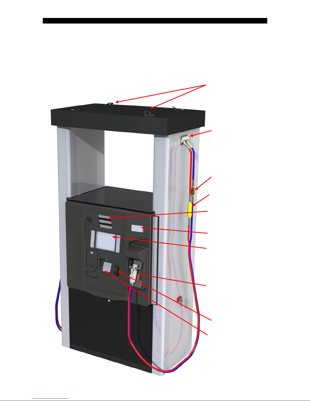
LIFTING
LUGS
HOSE
MANIFOLD
VENT LINE BREAKAWAY
MAIN LINE BREAKAWAY
PRICE, VOLUME, PRICE
PER UNIT DISPLAY
PRESSURE
POS DISPLAY
HOSE NOZZLE
CARD READER
ENCRYPTED KEYPAD
1.7.4 The Retail unit layout
A single-hose Retail CNG Optima™ dispenser—Please refer to the Engineering package for a view of internal components
©2014 Kraus Global Ltd.
6 Retail CNG Dispenser Manual
2. SAFETY
CAUTION
Compressed Natural Gas (CNG) can pose great danger if mishandled.
Please be sure to read and understand this section before installing,
operating, or maintaining CNG dispensers.
ADVICE
It is necessary to comply with all safety precautions and other instructions
described throughout this manual to properly install, operate, and maintain
Kraus-manufactured CNG dispensers.
2. SAFETY
2.1 General safety
Where it is applicable, local regulations take precedence over the
guidelines listed in this section. Please ensure that all personnel are
familiar with all applicable regulations and observe the following
guidelines when working with fuel dispensers:
Do not smoke or allow open flames and
naked lights within 15 feet or 5 meters of
any gas installation.
Do not adjust, remove, or bypass any
protective devices.
Electrical equipment and its protection
must comply with the regulations
applicable to the hazard of the location.
Transportation, installation,
commissioning, operation, maintenance,
and repairs should only be carried out by
qualified personnel in accordance with
the regulations for operation and safety.
Electrical connections must comply with
applicable local regulations.
Piping and other components, which are
not supplied by Kraus Global Ltd., must be
suitable for the respective working
pressure. If necessary, they must be
tested and protected by pressureunloading devices.
Systems must be entirely vented before
any maintenance or repair procedures
are carried out.
Do not store flammable materials, such as
oily rags, in or around the dispensing unit.
©2014 Kraus Global Ltd.
Retail CNG Dispenser Manual 7

2. SAFETY
2.2 Filling safety
Please observe the following guidelines when overseeing the use of
all Kraus-CNG dispensers:
Be aware of emergency procedures and
emergency telephone numbers.
Be aware of the locations of fire
extinguishers and the “Emergency Shut
Down” (ESD) buttons.
Ensure all operators and users are
properly trained before any fueling
transactions.
Do not allow any vehicles to be
unattended while fueling.
Ensure that all automatic transmission
vehicles are placed in “park” or the
emergency brake is applied for all manual
transmission vehicles before allowing any
fueling transactions.
Ensure that all vehicle ignitions, electrical
systems, and radios—including shortwave communication equipment—are
shut-off before allowing any fueling
transactions.
Ensure the fuel receptacle is inspected
and matches the dispenser filling nozzle
before attempting any fueling
transactions.
Ensure all users adhere to the operating
procedures described in Section 4.1 when
fueling.
Ensure all users are aware that pressure
from the nozzle must be vented before
disengaging it from the vehicle.
Ensure that all users replace the
dispenser nozzle firmly onto the holder
immediately after refueling.
©2014 Kraus Global Ltd.
8 Retail CNG Dispenser Manual
2. SAFETY
ATTENTION
The hose assembly for Retail CNG dispensers are designed to convey
static electricity. It is imperative that the hose assembly be properly
grounded to the CNG unit it is attached to.
ATTENTION
For additional information about dispenser hoses, please refer to the
specification tag provided by the manufacturer or contact Technical
Support at 204-663-3601, ext.212.
2.3 Dispenser hose safety
Please observe the following guidelines prior to installing or
maintaining CNG dispenser-hoses and related components:
Replace the hose if any of the following conditions are observed:
o The jacket of the hose appears abnormal
o A gas leak or any reason to believe there is a gas leak
o The couplings are damaged
o The hose is damaged in any way, including cuts, cracks,
bulges, blisters, or abrasions
o The reinforcement is exposed through the jacket
o Spring guards are missing or detached from couplings
o Couplings and spring guards show evidence of slippage or
looseness
Inspect the hose assembly before each
use.
Do not exceed the maximum
recommended working pressure of the
hose: 5,000 psi/345 bar.
Do not twist, kink, or torque the hose
assembly.
Never attempt to repair or re-couple a
damaged hose.
Do not use a strength member for pulling
or lifting equipment.
©2014 Kraus Global Ltd.
Retail CNG Dispenser Manual 9

2. SAFETY
2.4 Maintenance safety
Please observe the following guidelines prior to maintaining any
Kraus CNG dispenser:
Only properly trained or qualified
personnel should be permitted to
maintain and repair CNG equipment.
When in doubt, please refer to the
equipment supplier or service agent.
Always adhere to the manufacturer
guidelines for proper installation and
maintenance of all dispensers and
dispenser-components.
All maintenance and repair work of
pressure vessels and other safety
equipment must be conducted under the
appropriate codes, then tested and
accepted by the inspection authority.
The dispenser must be powered-off and
completely vented, unless otherwise
specified.
Never perform welding processes near
gas systems.
Always cover disassembled parts and
openings with a clean rag, paper, or
adhesive to keep them clean and avoid
contamination.
Do not clean any parts with flammable
solvent. Clean and rinse all parts carefully
with compressed air.
Be sure to wear necessary safety
equipment during maintenance and
repair. Eye protection is absolutely
necessary when cleaning with
compressed air.
Wear hearing, hand, and eye protection
when bleeding filters and lines. Be sure to
keep body parts away from the discharge
orifice.
Do not touch bare wires and live current-
carrying parts while the electrical system
is energized.
Never tighten or loosen any fitting when
it is under pressure.
©2014 Kraus Global Ltd.
10 Retail CNG Dispenser Manual
2. SAFETY
ADVICE
Never allow problems to go unreported. Both your company and supplier
will benefit from the full disclosure of all dispenser issues.
2.5 Leak test safety
Always use proper thread lubricants and
sealant on tapered pipe threads.
Never turn a fitting body. Instead, hold
fitting body and turn the nut.
After completing any work on process gas
piping systems and its components,
always purge the system thoroughly with
a non-corrosive inert gas, such as
nitrogen, before introducing natural gas.
Ensure that you have not left any tools,
cleaning equipment, or any loose parts
inside the dispenser.
Please observe the following guidelines before performing leak tests
on Kraus-manufactured CNG dispensers:
Ensure the area surrounding the
dispenser being serviced is closed off to
all customers and unauthorized
personnel. Use any appropriate barricade
and signage to ensure safety.
It is recommended that protective shields
be placed around potentially harmful
areas of the dispenser being serviced.
Service personnel must wear all
appropriate safety gear, such as helmets
with eye and/or facial protection and
body shields.
©2014 Kraus Global Ltd.
Retail CNG Dispenser Manual 11

3. INSTALLATION AND SETUP
3. INSTALLATION AND SETUP
3.1 Installation guidelines
Please observe the following guidelines prior to installing any Krausmanufactured CNG dispenser:
All electrical and mechanical installations
All electrical installations must only be
All high-pressure gas connections should
Safety valve discharge gases must be
Be sure to allow room inside the
Where soil displacement is apparent, gas
The dispenser frame enclosure must be
A pressure relief device may be installed
o The pressure relief device must communicate directly with
the pressure-containing component it is designed to
protect—valves between the protected component and the
inlet to the pressure relief device are not permitted.
must comply with the provisions of the
local authority having jurisdiction.
carried out by a licensed electrical
journeyman.
only be carried out by qualified and
experienced personnel.
funneled safely away from the working
area using tubing or piping with
comparable pressure ratings to the tubing
or piping used within the dispenser.
dispenser pit to properly tie-in the gas
lines to the inline filters and manual
isolation valves.
connections upstream of the dispenser
must be made with flexible hoses.
securely bolted to a concrete foundation
or to a structural steel base. Adequate
support must be provided for each unit of
the dispensing system, independent of
piping, tubing, or conduit that may be
connected to the dispenser.
directly upstream of the dispenser—in
compliance with the ASME Boiler and
Pressure Vessel Code—to limit the
pressure at the inlet of the dispenser to a
value no greater than the maximum
working pressure of the dispenser.
©2014 Kraus Global Ltd.
12 Retail CNG Dispenser Manual

3. INSTALLATION AND SETUP
All dispensers must be equipped with an
emergency shut-off device that will
terminate the gas supply to the dispenser
in the event that the dispenser is upset or
sheared from its foundation for any
reason.
All dispensers must only be used for gas
compositions specified within SAE J1616:
Recommended Practice for Compressed
Natural Gas Vehicle.
©2014 Kraus Global Ltd.
Retail CNG Dispenser Manual 13
3. INSTALLATION AND SETUP
CAUTION
Kraus CNG dispensers must be situated in such a way that there are no
obstructions, such as a wall or gate, that may entangle the dispenser
hose. This is to ensure proper functioning of the hose assembly’s
breakaway coupling.
ATTENTION
Please refer to your Construction drawings for dispenser dimensions.
3.2 Pre-installation
3.2.1 Site preparation
Please observe the following guidelines prior to constructing
dispenser pits:
Be sure to allow room inside the
dispenser pit to properly tie-in the gas
lines to the inline filters and manual
isolation valves.
Make provisions for tubing and electrical
conduits prior to pouring the concrete
pad.
Filters must be installed upstream of the
dispenser.
Due to potential weld slag, filings, rust,
dirt, and water, dispensing lines should be
purged to the atmosphere at the
dispenser. This can be done by blowing
nitrogen through the lines.
All dispensing lines must be purged,
pressurized, and leak tested. Afterwards,
manual isolating valves in the dispenser
pit must also be leak tested. The
dispenser must only be connected to the
lines after these have been accomplished.
©2014 Kraus Global Ltd.
14 Retail CNG Dispenser Manual

3. INSTALLATION AND SETUP
CAUTION
Ensure that the dispenser crate is placed on a smooth and level surface
before removing any crate panels.
ATTENTION
All dispenser packages contain additional parts, accessories, and
documents that are vital to the installation, operation, and maintenance of
the dispenser. Be sure to set these items aside in a safe and easily
accessible area.
Dispenser keys may be found on one of the authorization handles.
3.2.2 Uncrating the dispenser
1. Inspect the crate for any damages that may have occurred during
shipping. If any damages are found:
o Take pictures of the damages
o Note the damages
o Contact Kraus
2. Starting with the top panel, remove all screws and/or nails and
detach the top panel. Repeat this process to remove all side
panels.
3. Remove all protective wrapping by hand; knives and other sharp
objects may damage the dispenser.
4. Inspect the dispenser for any damages. If any damages are found,
repeat the procedure indicated in step 1.
5. Remove lag bolts from base rails to free the dispenser from the
bottom pallet.
6. Locate and review the crating check list to ensure that all items
are accounted for. If you are missing any items, please contact
Technical Support at 204-663-3601, ext.212.
©2014 Kraus Global Ltd.
Retail CNG Dispenser Manual 15
 Loading...