

Page 1

INSTALLATION GUIDE
Single Lever Pull Down Kitchen Faucet
Page 2
1
Please keep teh box and packaging materials until your product is
completely installed. If you have any questions, require technical
assistance, or have any problems with your product:
Have the model number available, and retain a copy of your receipt
with purchase date for reference.
If for any reason this product does not meet your expectations,
please be sure to repack this product in the original box and
packaging material to avoid damage during transit.
DO NOT RETURN TO STORE
Congratulations on the purchase of your new
plumbing xture!
Please contact our Customer Service Team
Page 3
2
Prior to Installation:
faucet to release any built up pressure. Remove existing faucet. Clean sink or
countertop to remove any debris, plumber’s putty, or silicone
• Place bucket under angle stops. Turn on to ush any debris prior to installing new
plumbing. Shut off angle stops
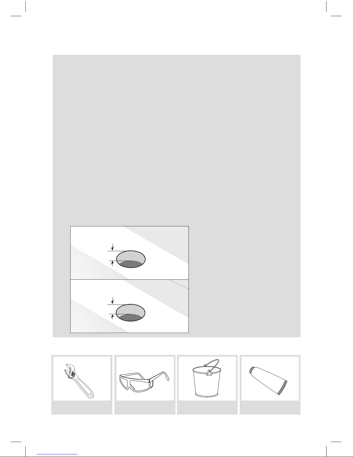
• Pre-drilled hole size requirement: 1-3/8” (min) – 1-1/2” (max)
• Max countertop thickness without deck plate: 1-1/2”
• Max countertop thickness with deck plate: 1”
• 1, 2, or 3 hole installation
Without deck plate:
With deck plate:
1/16” (1mm) min.
1-1/2” (38 mm) max.
Ø 1-3/8” (35 mm) min.
Ø 1-1/2” (38 mm) max.
1/16” (1mm) min.
1” (25.4 mm) max.
Ø 1-3/8” (35 mm) min.
Ø 1-1/2” (38 mm) max.
2
1A
1B
D
C
Tools you will need:
Adjustable Wrench
Safety Goggles Bucket Silicone Sealant
3/8”
(10mm)
7/8”
19.7
º
(22mm)
8 5/16”
1 1/4-18UNF-2A
(21mm)
10 1/8”
(257mm)
1 3/8”
(35mm)
3 3/4”
(96mm)
Phillips screwdriver
• Turn off the hot and cold water supply at the angle stops and turn on the old
• Make sure you have all necessary parts by checking the diagram and parts list.
If any part is missing or damaged, please contact our Customer Service
Page 4
3
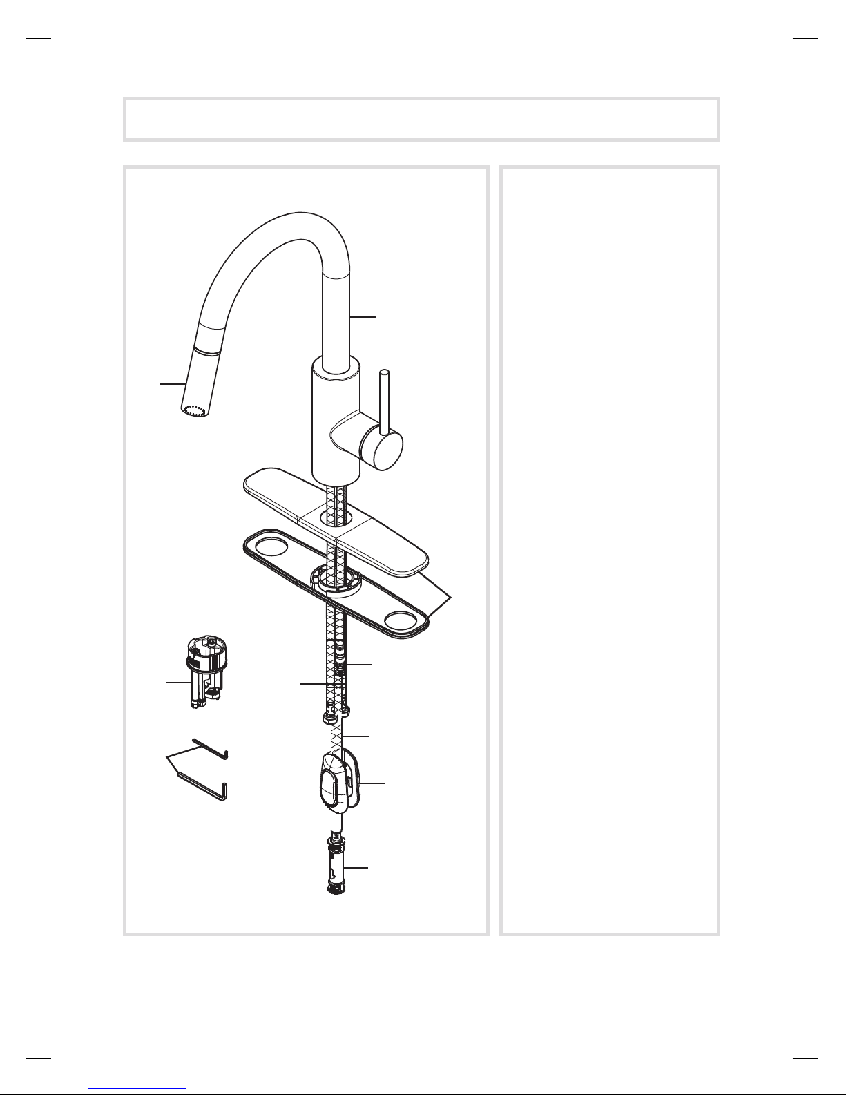
A. Spray Head
B. Faucet Body
C. Deck & Putty Plate
D. Supply Hose
E. Hot & Cold Waterlines
F. Spray Hose
G. Weight
H. Quick Connect
I. Hex Wrench
i1. 2.5mm
i2. 4mm
J. Base
Diagram and Parts List
A
J
C
B
F
D
I
E
G
H
Page 5
4
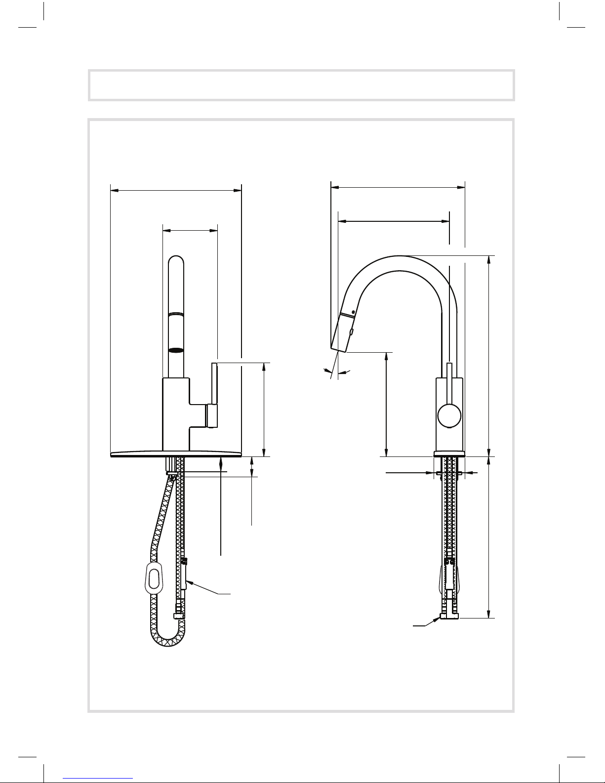
3/8” Compression
Check Value
221mm
62mm
186mm
208mm
400mm
260mm
109mm
267mm
1mm~30mm
40mm
620mm
15
º
10 1/4"
4 1/4"
7 1/4"
1 5/8"
1/16"-1 1/8”
15 3/4"24 1/2"
2 1/2"
8 1/4"
8 3/4"
10 1/2"
9/16-24UNEF
Faucet Dimensions
Page 6

5
Step 1A: Install base without deck & putty plate
Half Moon Locking Nuts
J
i2
Insert base (J) into sink or countertop with “FR↑NT” facing forward. Tighten
screws on base (J) with 4mm hex wrench (i2) until base is secure on sink or
countertop
Installer Tip: Rotate the two half-moon shaped locking nuts inward
before inserting base (J) into sink or countertop
Page 7

6
Step 1B: Install base with deck & putty plate
1
2
1B
C
D
2
J
i2
Place a bead of clear silicone sealant (not included) around the edge of the
putty plate (C). Secure deck & putty plate (C) on sink or countertop. Insert
base (J) into hole of deck & putty plate (C) with “ FR↑NT” facing forward.
Tighten screws on base (J) with 4mm hex wrench (i2) until base is secure on
deck & putty plate (C)
Installer Tip: Rotate the two half-moon shaped locking nuts inward
before inserting base (J) into deck plate (C)
Page 8

7
Step 2: Install faucet
Step 3: Secure faucet
Align arrow on faucet body
(B) with arrow on base (J).
Attach faucet body (B) to base
(J). Secure faucet body (B) by
tightening the set screw with
2.5mm hex wrench (i1)
Installer Tip: Please loosen
set screw from faucet
body (B) prior to securing
to base (J)
Note: “ “ on base should be in
alignment with “ “ on faucet body.
Remove Quick Connect (H)
from spray hose (F). Insert
spray hose (F) into small
hole of base (J). Insert hot
& cold waterlines(E) and
supply hose (D), one by
one, in large hole of base
E
E
D
D
D
E
F
F
B
J
i1
Page 9

8
Step 4: Connect waterlines to main valve
Step 5: Connect quick connect
Thread hot & cold waterlines
(E) onto angle stops. Tighten
with adjustable wrench until
snug. Turn on the angle stops
and check for leaks (DO NOT
TURN FAUCET ON)
Attach Quick Connect (H) with
black end onto spray hose (F)
until you hear a click. Attach
the other end onto the supply
hose (D) until you hear a click.
Installer Tip: Use two
wrenches when securing
waterlines to angle stops
to prevent kinking, as
shown in picture
E
D
D
H
D
F
F
F
E
E
Hot
Cold
Page 10

9
Step 6: Install weight
Step 7: Flush faucet
Attach weight (G) on the
designated mark on the spray
hose (F)
Remove spray head (A). Hold tip
of spray hose (F). Turn faucet on
for 1 minute to ush any debris.
Reconnect spray head (A)
B
D
J
Designated Mark
F
F
F
A
A
G
F
F
A
F
A
Page 11

10
Replacement Part List
Care & Maintenance
*To keep the product clean & shining, follow the steps below:
*This installation manual is subject to change without further notice.
1. Rinse with clean water & dry with a soft cloth
2. Do not clean with soaps, acid, polish, abrasives, or harsh cleaners
3. Do not use cloth with a coarse surface
4. Unscrew the aerator and clean when necessary
Hot
Water
Cold
Water
Push
1. Spray Head
2. Washer
3. Hose Guide
4. Spout Clip
5. Set Screw
6. Catridge
7. Locking Nut
8. Catridge Cover
9. Metal Handle
10. A Set Screw
B Index Button
11. Cover Plate
12. Putty Plate
13. Quick Connect
Assembly
14. Spray Hose
15. Weight
16. Base
17. Hex Wrench
(2.5mm)
18. Hex Wrench
(4mm)
1
2
3
5
4
6
7
8
9
10A
10B
13
14
15
11
12
16
17
18
Page 12

11
Trouble - Shooting
If you have followed the instructions carefully and your faucet still does not work
properly, take the following corrective steps:
PROBLEM CAUSE ACTION
Leaking from spray
hose
Quick Connect (8) may
be installed incorrectly
Remove Quick Connect
(8) from spray hose (9)
and reinstall. Make sure
you hear a click when
you install it on the spray
hose (9)
Water will not shut off
completely
Cartridge (5) may
need to be adjusted or
replaced
Remove index button
(1A). Loosen set screw
(1B) with 2.5mm hex
wrench (13). Remove
metal handle (2).
Remove cartridge
cover (3) by hand only.
Remove locking nut
(4) with an adjustable
wrench. Remove
ceramic disc cartridge
(5). Check for cracks
Hose does not retract Weight (10) may be
installed incorrectly
Readjust weight (10)
on the hose (9). Make
sure it is installed on the
designated mark on the
hose (9)
Low flow Quick Connect (8) may
be clogged with debris
Remove Quick Connect
(8) from hoses. Soak in
50/50 solution of warm
water and vinegar for 5
minutes, then reinstall
Page 13

12
Codes / Standards Applicable:
Meets ASME A112.18.1M/A112.18.1
1.75gpm 6.6L/min maximum
GREEN
Water Eciency
LEAD FREE
I
A
P
M
O
R
&
T
TM
NSF/ANSI Standard 61 certied by IAPMO
NSF/ANSI Standard 372 certied by IAPMO
FAUCET WARRANTY
Page 14

13
In requesting warranty service, please be ready to provide:
1. Proof of purchase.
2. A description of the problem.
Page 15

IMPORTANT
 Loading...