

Page 1

INSTALLATION GUIDE
Single Lever Pull-Out
Kitchen Mixer
KPF-1622
www.kraususa.com I Toll Free: 1.800.775.0703 I ©2017 Kraus USA Inc. I REV. August 7, 2017
Page 2

Congratulations on the purchase of your new
Kraus plumbing xture!
Please keep teh box and packaging materials until your product is
completely installed. If you have any questions, require technical
assistance, or have any problems with your product:
DO NOT RETURN TO STORE
Please contact our Customer Service Team
1-800-775-0703 / customerservice@kraususa.com
Have the model number available, and retain a copy of your receipt
with purchase date for reference.
If for any reason this product does not meet your expectations,
please be sure to repack this product in the original box and
packaging material to avoid damage during transit.
1
Page 3

6 5/8”
5 4/5”
3/8”
(10mm)
7/8”
19.7
º
(22mm)
8 5/16”
1 1/4-18UNF-2A
(21mm)
10 1/8”
(257mm)
1 3/8”
(35mm)
3 3/4”
(168mm)
(147.3mm)
(96mm)
19.7
8 5/16”
1 1/4-18UNF-2A
(21mm)
10 1/8”
(257mm)
1 3/8”
(35mm)
PRIOR TO INSTALLATION
• Make sure you have all necessary parts by checking the diagram and parts
list. If any part is missing or damaged, please contact Kraus Customer
Service at 800-775-0703 for a replacement
• Turn o the hot and cold water supply at the angle stops and turn on the
old faucet to release any built up pressure. Remove existing faucet. Clean
sink or countertop to remove any debris, plumber’s putty, or silicone
• Place bucket under angle stops. Turn on to ush any debris prior to
installing new plumbing. Shut o angle stops
• Pre-drilled hole size requirement: 1-3/8”
• Max countertop thickness without deck plate: 1-3/8”
For technical assistance or replacement parts, please contact Kraus
Customer Service and one of our representatives will be happy to help:
Toll-Free: 800-775-0703 or Customerservice@kraususa.com
Tools Required
Adjustable Wrench
Phillips Screwdriver
Safety Goggles
Bucket
Silicone Sealant
2
Page 4
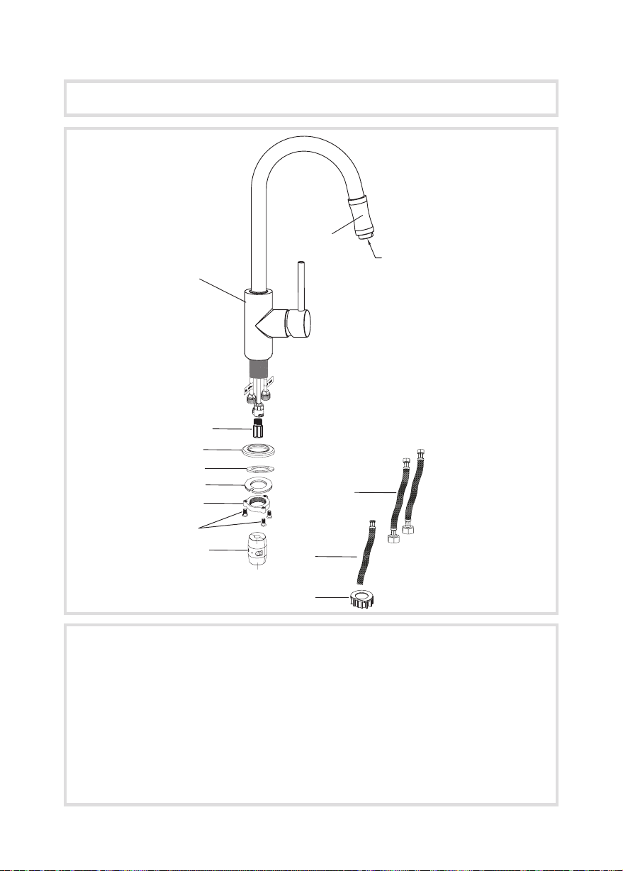
Diagram and Parts List
Included Parts:
1. Faucet Body
2. Aerator Head
3. Base
4. Base O-Ring
5. Rubber Washer
6. Mounting Nut
7. Mounting Screws
8. Weight
9. Hot & Cold Waterlines
10. Spray Hose
11. Spacer
KPF-1622 Diagram and Parts List
Pull Out Hose
14 3/4”
3
2
Aerator
Pull Out Hose
14 3/4”
1
4
5
6
7
8
9
10 12
11
3
2
Aerator
14 3/4”
1
4
5
6
7
8
9
10 12
13
11
12. Check Valve
A
1
12
J
3
C
D
4
5
E1
6
E2
E3
7
8
F
A. Faucet Body
B. Aerator Head
C. Base
D. Base O-Ring
E. Mounting Hardware Assembly
E1 Rubber& Metal Washer
E2 Mounting Nut
E3 Mounting Screws
3
2
B
9
G
10
H
I
11
F. Weight
G. Hot & Cold Waterlines
H. Spray Hose
I. Spacer
J. Check Valve
Aerator
Page 5

Faucet Dimensions
360°
7”
(179 mm)
12°
8 -1/4”
(209 mm)
2 -1/8”
2 -5/8”
(53 mm)
(66 mm)
5-3/8”
6 -7/8”
(135 mm)
(175 mm)
9 -3/8”
(239 mm)
4
Page 6

Faucet Dimensions
(179 mm)
2 -5/8”
(66 mm)
2 -1/8”
(53 mm)
360°
14 -7/8”
(377 mm)
5
Page 7

Faucet Installation Methods
Installation Method 1
The minimum distance between
the faucet hole and wall should
be 3.5”
Less than
Faucet Installation Methods
Installation Method 1
The minimum distance between
the faucet hole and wall should
be 3.5”
If the distance between the
faucet hole and the wall is less
than 3.5”, position the faucet
lever 30 degrees to 90 degrees
off the wall to allow for full
operation
Mi
nimum d
istance 3.5
Less than
Mi
Less than
Faucet Installation Procedures
Installation Method 1
Mi
istance 3.5
nimum d
The minimum distance between
the faucet hole and the wall should
be 3.5”
Installation Method 2 (optional)
istance 3.5
nimum d
If the distance between the faucet
hole and the wall is less than 3.5,”
position the faucet lever 30° to
90° off the wall to allow for full
operation
6
Page 8

Step 1
Step 1
Installation Steps
Step 1
Ø35~Ø38
Ø1
~Ø1
Step 1
1
Installation Steps
Step 2
Hot
Water
Cold
Water
Step 1
Step 2
Ø35~Ø38
Ø1
~Ø1
Remove mounting hardware
assembly (E)
1
E1
E2
E3
Connect waterlines (G) to hot and
cold copper lines on faucet
Installer Tip
Use two wrenches when
securing waterlines (G) to
copper lines to prevent kinking,
as shown in picture
7
Page 9

2. Insert the faucet body (1) into the hole on the deck with the base
(4) and base o-ring (5), and then install the rubber washer (6),
metal washer (7), mounting nut (8) and mounting screws (9) from
underneath the sink.
4
5
6
7
8
9
Step 3
2. Insert the faucet body (1) into the hole on the deck with the base
(4) and base o-ring (5), and then install the rubber washer (6),
metal washer (7), mounting nut (8) and mounting screws (9) from
underneath the sink.
4
5
6
7
8
9
Step 4
Step 3
Step 3
A
Insert faucet body (A) into hole
on deck or sink with base (C) and
base o-ring (D) attached. Attach
mounting hardware assembly (E)
C
D
E3
E1
E2
Adjust faucet body (A). Secure
A
mounting hardware (E) with
wrench and Phillips head
screwdriver
Step 4
E
8
Page 10

Hot
Water
Cold
Water
Step 5
Step 6
4. Connect the spray h
with a wrench until snug
hose (12). Connect h
and tighten with a wrench, then turn on water supplies and check
leaks.
Step 5
4. Connect the spray h
with a wrench until snug
hose (12). Connect h
and tighten with a wrench, then turn on water supplies and check
leaks.
Step 5
Step 6
A
Connect spray hose (H) to check
valve (J) and tighten with an
adjustable wrench.
Installer Tip
Insert washer
J
H
Attach weight (F) to lowest point
vertically on spray hose (H)
9
F
Connect and tighten waterlines (G)
to angle stops. Turn on the angle
stops and check for leaks
(DO NOT TURN FAUCET ON)
Installer Tip
Remove aerator and turn faucet on
for 60 seconds to flush any debris
Page 11

25˚
Close
Open
Usage
How to Operate the Handle
Usage
How to operate the handle:
Close
˚
110
25˚
Open
1. Pull the lever to the right to
Pull the lever to the right to turn
1.
turn on the water. Push to the
left to turn off
on the water. Push to the left to
turn off
2. Pull the lever forward to
increase hot water flow and
Pull the lever forward to
2.
push the lever back to increase
the cold water flow
increase hot water flow and
push the lever back to increase
the cold water flow
Left
Hot Water
Right
Cold Water
10
Page 12

Replacement Parts
22
23
12
15
19
20
21
17
13
14
16
1. Aerator Assembly
2. Hose
3. Aerator Head
3
2
1c
1b
1a
4
5
8
6
11
10
24
7
9
18
4. Set Screw
5. Cap
6. Set Screw
7. Cap
8. Handle
9. Cartridge Cover
10. Locking Nut
11. Cartridge
12. Base
13. Base O-Ring
14. Rubber & Metal Washer
15. Mounting Nut
16. Mounting Screw
17. Protective Sleeve
18. Weight
19. Check Valves
20. Connector
21. Washer
22. Hot & Cold Waterlines
23. Hex Wrenches 2mm &
2.5mm
24. Spacer (Optional)
Care & Maintenance
*To keep the product clean & shining, follow the steps below:
1. Rinse with clean water & dry with a soft cloth
2. Do not clean with soaps, acid, polish, abrasives, or harsh cleaners
3. Do not use cloth with a coarse surface
4. Unscrew the aerator and clean when necessary
*This installation manual is subject to change without further notice.
11
Page 13

Trouble - Shooting
If you have followed the instructions carefully and your faucet still does not work
properly, take the following corrective steps:
PROBLEM CAUSE ACTION
Leakage under handle
(8)
Water will not shut off
completely
Locking nut (10) has
come loose
Cartridge (11 ) may be
defective
Remove cap (7) at
bottom of handle
(8). Loosen set screw
(6) with 2.5mm hex
wrench (23). Remove
the handle (8) and
unscrew cartridge cover
(9) by hand. Tighten
locking nut (10) with an
adjustable wrench
Remove cap (7) at
bottom of handle
(8). Loosen set screw
(6) with 2.5mm hex
wrench (23). Remove
the handle (8) and
unscrew cartridge cover
(9) by hand. Unscrew
locking nut (10) with
an adjustable wrench.
Remove ceramic disc
cartridge. Check for
cracks
Aerator (1) drips or has
inconsistent water
flow pattern
Aerator (1) is dirty or
not seated properly
Unscrew aerator (1)
by hand and clean out
debris
12
Page 14

Codes/Standards Applicable:
GREEN
NSF/ANSI Standard 61 certied by IAPMO
NSF/ANSI Standard 372 certied by IAPMO
Water Eciency
LEAD FREE
I
A
P
M
O
R
&
T
TM
Meets ASME A112.18.1M/A112.18.1
1.75gpm 6.6L/min maximum
FAUCET WARRANTY
Kraus products are manufactured and tested to the highest quality standards by Kraus USA Inc. (“Kraus”). Kraus extends
this warranty to the original purchaser for personal household use of the “Faucet” in its original location. The warranty
is non-transferable.
Kraus warrants the structure and nish of the product to be free from defects in material and workmanship under
normal usage for the lifetime of the product. The warranty commences from the initial date of purchase by the owner or
trade professional, from an authorized Kraus dealer, through the lifetime of
the original owner or end-user.
Kraus warrants the mechanical component (sprayhead assembly) of the product to be free from defects in material
and workmanship under normal usage for a period of one (1) year. The warranty commences from the initial date of
purchase by the owner or trade professional, from an authorized Kraus dealer, through the one (1) year term of the
original owner or end-user.
Kraus warrants the mechanical component (cartridge) of the product to be free from defects in material and
workmanship under normal usage for a period of ve (5) years. The warranty commences from the initial date of
purchase by the owner or trade professional, from an authorized Kraus dealer, through the ve (5) year term of the
original owner or end-user.
Any product reported to the authorized dealer or to Kraus as being defective within the warranty
or replaced with a product of equal value at the option of Kraus. This warranty
extends to the original owner or end-user,
period will be repaired
and is not transferable to a subsequent owner.
RESTRICTIONS
This warranty does not cover antediluvian, discontinued, or display products, whether such items are purchased at
discount outlets, unauthorized dealers, and/or sold on clearance. This warranty does not cover instances of negligence,
misuse, abuse, improper installation, carelessness, accident, hard water or mineral deposits, exposure to corrosive
materials, misapplication, damages caused by improper maintenance, alteration of the product, or failure to follow care
or installation instructions enclosed with your product. Avoid using abrasive cleaners such as powders, bleach, ammonia,
alcohol, or
nish.
This warranty does not apply to Products that have not been installed or operated in accordance with instructions
supplied by Kraus and all applicable rules, regulations, and legiswlation pertaining to such installations.
This warranty does not apply unless the Kraus product is installed by a fully insured and licensed trade professional.
Kraus insists that such professionals have experience in the installation of bathroom and kitchen manufactured goods.
This warranty does not cover labor charges or costs of removal and reinstallation of said product. This warranty does
not allow recovery of incidental or consequential damages, such as loss of use, delay, property damage, or other
consequential damages, and Kraus accepts no liability for such damages.
This warranty does not cover Marine or Outdoor Installation.
chlorine. Avoid using abrasive pads, steel wool, or wire brushes, as these will damage and wear down the
Except as otherwise provided above, Kraus makes no warranties, expressed or implied, including warranties of
merchantability and tness for a particular purpose, or compliance with any code. Shipping charges will be covered for
13
Page 15

the rst (1) year of the warranted replacement part or product (HI, AK, and Puerto Rico shipping charges may apply).
International shipping fees are not included.
COMMERCIAL WARRANTY
Kraus extends the above warranty for a period of one (1) year to purchasers of products for industrial, commercial, and
business use.
All incidental or consequential damages are specically excluded. No additional warranties, express or implied, are given,
including but not limited to any implied warranty of merchantability or tness for a particular purpose.
ome states do not allow the exclusion or limitation of incidental or consequential damages or limitations on how long an
implied warranty lasts, so the above limitations or exclusions may not apply to you.
This warranty gives you specic legal rights, and you may also have other rights which vary from state to state.
If you are a homeowner please contact a Kraus Customer Service Representative at:
Kraus USA, Inc.
12 Harbor Park Drive
Port Washington, NY 11050
Toll-free 800-775-0703
Customerservice@kraususa.com
If you are a plumbing contractor or trade professional please contact a Kraus
Pro Representative at:
Kraus USA, Inc.
12 Harbor Park Drive
Port Washington, NY 11050
516-801-8955
Proservice@kraususa.com
If you are an Authorized Partner please contact a Partner Support Representative at:
Kraus USA, Inc.
12 Harbor Park Drive
Port Washington, NY 11050
516-801-8954
Partnersupport@kraususa.com
In requesting warranty service, please be ready to provide:
1. Proof of purchase.
2. A description of the problem.
Download the Kraus Care & Maintenance Guide at:
http://www.kraususa.com/maintenance
14
Page 16

IMPORTANT
Register Your Kraus Product
Activate Your Warranty
Access Premium Customer Support
Get Product Information
REGISTER TODAY
http://www.kraususa.com/registration
www.kraususa.com
 Loading...