


Wireless
WirelessWireless
Wireless----N Broadband
N Broadband N Broadband
N Broadband Router
Router Router
Router
3000Mbps / 2T2R
3000Mbps / 2T2R3000Mbps / 2T2R
3000Mbps / 2T2R
User Guide
Cod. KR.2N

KR.2N
Wireless-N Broadband Router 300Mbps / 2T2R
2 www.kraun.it
Content
CHAPTER 1: PRODUCT OVERVIEW.............................................................................4
1.1 P
RODUCT INTRODUCTION
........................................................................................4
1.2 P
RODUCT FEATURES
...............................................................................................4
1.3 P
ACKAGE CONTENTS
..............................................................................................5
CHAPTER 2::::GETTING TO KNOW THE ROUTER.......................................................6
2.1 R
EAR PANEL AND PORT DESCRIPTION
......................................................................6
2.2 F
RONT PANEL AND
LED D
ESCRIPTION
......................................................................7
2.3 H
ARDWARE INSTALLATION
........................................................................................8
CHAPTER 3. WEB MANAGEMENT INTERFACE ..........................................................9
3.1 N
ETWORK CONFIGURATION OF YOUR COMPUTER
......................................................9
3.2 V
ERIFYING THE CONNECTION
...................................................................................10
3.3 L
OGGING IN TO THE ROUTER
....................................................................................11
CHAPTER 4::::CONNECTION SETTINGS ......................................................................12
4.1 WAN C
ONNECTION SETTING
...................................................................................12
4.1.1 Select Connection Method.............................................................................12
4.1.2 Save Connection Settings .............................................................................14
4.1.3 Reboot and Connect......................................................................................14
4.1.4 Check Connection Settings............................................................................15
CHAPTER 5::::ADVANCED SETTING.............................................................................16
5.1 LAN S
ETTING
.........................................................................................................16
5.2 MAC A
DDRESS CLONE
...........................................................................................16
5.3 DNS S
ETTINGS
......................................................................................................17
5.4. WAN S
ETTINGS
.....................................................................................................18
5.4.1 PPPoE...........................................................................................................18
5.4.2 Static IP.........................................................................................................19
5.4.3 L2TP .............................................................................................................19
5.4.4 PPTP.............................................................................................................20
5.5 WAN M
EDIUM
........................................................................................................20
5.6 S
AVE CONNECTION SETTINGS
..................................................................................21
CHAPTER 6::::WIRELESS SETTINGS............................................................................22
6.1 E
NABLE WIRELESS MODE
........................................................................................22
6.2 B
ASIC SETTING
.......................................................................................................22
6.3 W
IRELESS SECURITY SETTINGS
...............................................................................23
6.3.1 Mixed WEP....................................................................................................23
6.3.2 WPA: Personal..............................................................................................24
6.3.3 WPA2-Personal.............................................................................................25
6.3.4 WPA-Enterprise.............................................................................................25
6.3.5 WPA2-Enterprise...........................................................................................26
6.3.6 802.1X Authentication....................................................................................27
6.4 WPS S
ETTING
........................................................................................................28
6.5 WDS S
ETTING
.......................................................................................................29

KR.2N
Wireless-N Broadband Router 300Mbps / 2T2R
3 www.kraun.it
6.6 A
DVANCED WIRELESS SETTING
................................................................................30
6.7 W
IRELESS ACCESS CONTROL
..................................................................................31
6.8 W
IRELESS CONNECTION STATUS
..............................................................................31
CHAPTER 7: DHCP SERVER......................................................................................... 32
7.1 DHCP S
ERVER SETTING
.........................................................................................32
7.2 DHCP C
LIENT LIST
.................................................................................................32
CHAPTER 8::::VIRTUAL SERVER..................................................................................33
8.1 S
INGLE PORT FORWARDING
.....................................................................................33
8.2 P
ORT RANGE FORWARDING
.....................................................................................34
8.3 P
ORT TRIGGER SETTING
.........................................................................................35
8.4 ALG S
ERVICE SETTING
...........................................................................................36
8.5 DMZ H
OST
............................................................................................................37
8.6 UPNP S
ETTING
......................................................................................................37
CHAPTER 9: TRAFFIC CONTROL ................................................................................38
CHAPTER 10: SECURITY SETTING..............................................................................39
10.1 C
LIENT FILTER SETTINGS
.......................................................................................39
10.2 URL F
ILTER
..........................................................................................................40
10.3 MAC A
DDRESS FILTER
..........................................................................................41
10.4 P
REVENT NETWORK ATTACK
..................................................................................42
10.5 R
EMOTE WEB MANAGEMENT
.................................................................................42
10.6 L
OCAL WEB MANAGEMENT
....................................................................................43
10.7 WAN P
ING
...........................................................................................................43
CHAPTER 11: ROUTING SETTING................................................................................44
11.1 R
OUTING TABLE
....................................................................................................44
11.2 S
TATIC ROUTING
...................................................................................................44
CHAPTER 12: SYSTEM TOOLS ....................................................................................45
12.1 T
IME SETTING
.......................................................................................................45
12.2 DDNS .................................................................................................................46
12.3 B
ACKUP
/ R
ESTORE SETTINGS
...............................................................................46
12.4 F
IRMWARE UPGRADE
............................................................................................48
12.5 R
ESTORE TO FACTORY DEFAULT SETTINGS
.............................................................49
12.6 R
EBOOT
...............................................................................................................49
12.7 P
ASSWORD CHANGE
.............................................................................................50
12.8 S
YSTEM LOG
........................................................................................................50
APPENDIX I: GLOSSARY..............................................................................................51
DICHIARAZIONE DI CONFORMITÀ SINTETICA ...........................................................53
SHORT DECLARATION OF CONFORMITY...................................................................53

KR.2N
Wireless-N Broadband Router 300Mbps / 2T2R
4 www.kraun.it
Chapter 1: Product Overview
1.1 Product Introduction
KR.2N 300Mbps Wireless Broadband Router with integrated antenna. It integrates wireless
router, 4-Port LAN switch and Firewall in one. KR.2N utilizes advanced MIMO technology and
increases over 8 times the transmission range of ordinary 802.11g products. Compatible with
IEEE802.11n (Draft 2.0) and IEEE802.11g/b standards, it can provide up to 300Mbps stable
transmission rate.
It supports WDS (Wireless Distribution System) function for repeating and amplifying the
signals to extend the wireless network coverage. For added security SSID broadcast may be
disabled. WPS (PBC and PIN) encryption method, port filtering and MAC address filtering can
protect your network from malicious attack. KR.2N can be managed through local / remote
Web management interface from anywhere. WMM functionality is supported for smoother
voice and video streams.
1.2 Product Features
• Integrates Wireless Router, four-port LAN switch and firewall
•
Complies with IEEE802.11n (Draft 2.0), IEEE802.11b and IEEE802.11g standards
• MIMO technology utilizes reflection signals to increase 8 times transmission distance of
original
802.11g standard and reduces the "dead spots" in the wireless coverage area
• Provides 300Mbps receiving rate and 300Mbps sending rate
• Supports WMM to make your voice and video more smooth
• Supports 64/128-bit WEP, WPA, WPA2 encryption methods and 802.1x security
authentication standard
• Setup Wizard support for fast and easy configurations
•
WPS (PBC and PIN) encryption method to free you from remembering long passwords
• Supports remote/local Web management
• Supports wireless Roaming technology to ensure high-
efficient wireless connections
• Supports wireless SSID stealth mode and MAC address access control
• Supports Auto MDI/MDIX
• Provides system log to record the status of the router
• Supports MAC addre
ss filtering, IP address filtering, URL filtering and NAT rules
• Supports UPnP and DDNS
• Supports access control over 30 MAC address entries
• Supports DHCP server/client
• Supports SNTP
• Supports virtual server and DMZ host
• Supports bandwidth control based on IP address range
• Built-in firewall to prevent hacker attack
• Supports auto wireless channel selection
• Supports WDS function (Wireless Distribution System)

KR.2N
Wireless-N Broadband Router 300Mbps / 2T2R
5 www.kraun.it
1.3 Package Contents
• One KR.2N Wireless-N Router
• One CD-ROM (User Guide, Setup Wizard, etc.)
• One Quick Installation Guide
• One RJ45 Ethernet Cable
• One Power Adapter
If any of listed items are missing or damaged, please contact the dealer from whom you
purchased the product.

KR.2N
Wireless-N Broadband Router 300Mbps / 2T2R
6 www.kraun.it
Chapter 2::::Getting to know the Router
2.1 Rear Panel and Port Description
Rear Panel Description
Rear Panel View
Rear Panel
Interface
Description
LAN(1-4)
Connect with your PC’s, Network devices or
uplink to hub or switch.
RESET/WPS
Note: Pressing this button for 7 seconds, the
settings stored will be deleted and restored to
factory default setting. If pressed for 1 second,
WPS (PBC) is enabled.
WAN Connect with Modem.
POWER For connecting the Power Adapter
KR.2N
Wireless-N Broadband Router 300Mbps / 2T2R
7 www.kraun.it
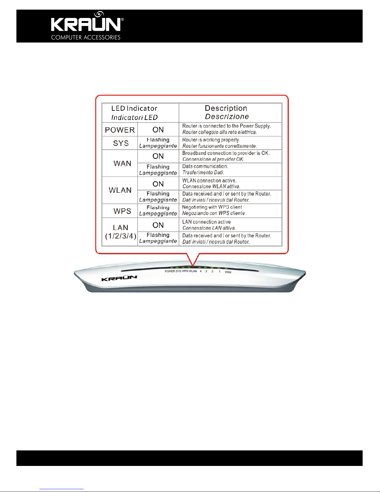
2.2 Front Panel and LED Description
Refer to the table below for the LED indicators located at the front panel, and their function.

KR.2N
Wireless-N Broadband Router 300Mbps / 2T2R
8 www.kraun.it
2.3 Hardware Installation
Before configuring the Router, please set up your hardware according to the following
diagrams. For better wireless performance, please place the Router in the center of the area
where you would like to have wireless coverage.
1. Make sure that your Internet
Access Device, such as Cable
Modem, xDSL Modem etc. is
connected correctly and operational.
2. Connect the Power Adapter to
the POWER interface of the
WIRELESS-N 300Mbps / 2T2R
Router. Use an Ethernet cable
to connect the WAN Interface
of the Router to the Internet
Access Device
CAUTION: Only use the Power Adapter that came with your Router. Use of other
Power Adapter may damage your Router and will void the Product Warranty.
3. Use an Ethernet cable to connect the LAN interface of the WIRELESS-N ROUTER
300Mbps / 2T2R to the NIC of the computer.

KR.2N
Wireless-N Broadband Router 300Mbps / 2T2R
9 www.kraun.it
Chapter 3. WEB Management Interface
3.1 Network Configuration of Your Computer
3.1.1 On the desktop of your computer, right-
click “My Network Places”, and then select
“Properties” in the shortcut menu.
3.1.2 In the window that appears, right-click
“Local Area Connection”, and then select
"Properties” in the shortcut menu.
3.1.3 In the pop-up dialog box check “Internet
Protocol (TCP/IP)” and then click “Properties”.

KR.2N
Wireless-N Broadband Router 300Mbps / 2T2R
10 www.kraun.it
3.1.4 In the window that appears, select “Obtain
an IP address automatically (O)” or “Use the
following IP address (S)”.
1) When “Obtain an IP address automatically
(O)” is selected, the window is as shown in the
right figure.
2) Click “Use the following IP address” and enter
details as follows:
IP address: 192.168.0.XXX
(XXX range 2 ~ 254)
Subnet mask: 255.255.255.0
Default gateway: 192.168.0.1
DNS server: Enter the local DNS server address
(for this address, you can consult your ISP) or
the router as the DNS server.
At the end of the setting, click “OK” to submit the
settings. And then click “OK” in the “Local Area
Connection Properties” window.
3.2 Verifying the Connection
3.2.1 If you are unable to access the
Management screen through the browser at
192.168.0.1, select “Start->Programs-
>Accessories->Command Prompt”.
This will open a Command Window. At the
Prompt, enter “Ping 192.168.0.1” and press
Enter. If the system gives the result shown in
the right figure, the connection between your
computer and the router is normal.
KR.2N
Wireless-N Broadband Router 300Mbps / 2T2R
11 www.kraun.it
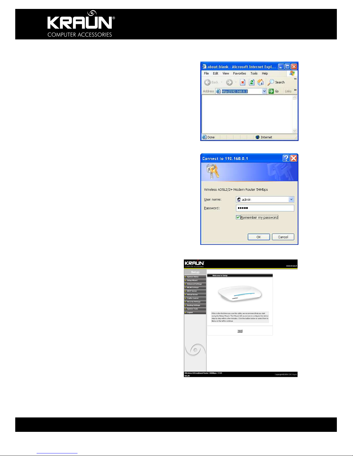
3.3 Logging in to the Router
3.3.1 Open the WEB browser, and enter
“http://192.168.0.1” in the address box. Press
Enter to navigate to the Web Interface Screen.
3.3.2 In the pop-up login window enter the User
name and Password and click “OK”.
Default Factory Settings:
User name: admin
Password: admin
3.3.3 If the user name and password entered
are correct, the browser displays the
administrator window. Click ‘Next’ to start the
Setup Wizard.

KR.2N
Wireless-N Broadband Router 300Mbps / 2T2R
12 www.kraun.it
Chapter 4::::Connection Settings
For first time installations we recommend to use the Setup Wizard. Open the Setup Wizard
window by clicking on the appropriate Menu selection on the left hand menu. Follow the onscreen instructions and select the required options from the drop-down lists or check boxes,
such as “Country”, “Area” and the like. For proper connection you need to know the method
used by your ISP to connect to the network. If in doubt, contact your ISP and get all required
connection details before continuing.
4.1 WAN Connection Setting
The Router supports five common connection modes (ADSL Virtual Dial-up, Dynamic IP,
Static IP, L2TP and PPTP). Select one according your actual requirements or click ‘Detect’
and let the Wizard determine to most suitable connection method.
4.1.1 Select Connection Method
From the available options, select the connection method advised by your ISP
4.1.1.1 Connection Mode 1: ADSL Virtual Dial-up (Via PPPoE).
Enter the Account or User Name and Password provided by your ISP, and click “Next”.
4.1.1.2 Connection Mode 2: Dynamic IP (Via DHCP)
If your connection mode is Dynamic IP, your IP address will change every time you connect.
You do not need to enter any information. The Router will connect automatically.

KR.2N
Wireless-N Broadband Router 300Mbps / 2T2R
13 www.kraun.it
4.1.1.3 Connection Mode 3: Static IP
Enter the network address information provided by your ISP in the IP Address, Subnet Mask,
Gateway and Primary DNS server fields. Click “Next”.
4.1.1.4 Connection Mode 4: L2TP
Enter the details provided by your ISP such as User Name and Password.
L2TP provides two access modes. Select the one advised by your ISP.
Dynamic IP
Static IP
After entering all details, click “Next”.
KR.2N
Wireless-N Broadband Router 300Mbps / 2T2R
14 www.kraun.it
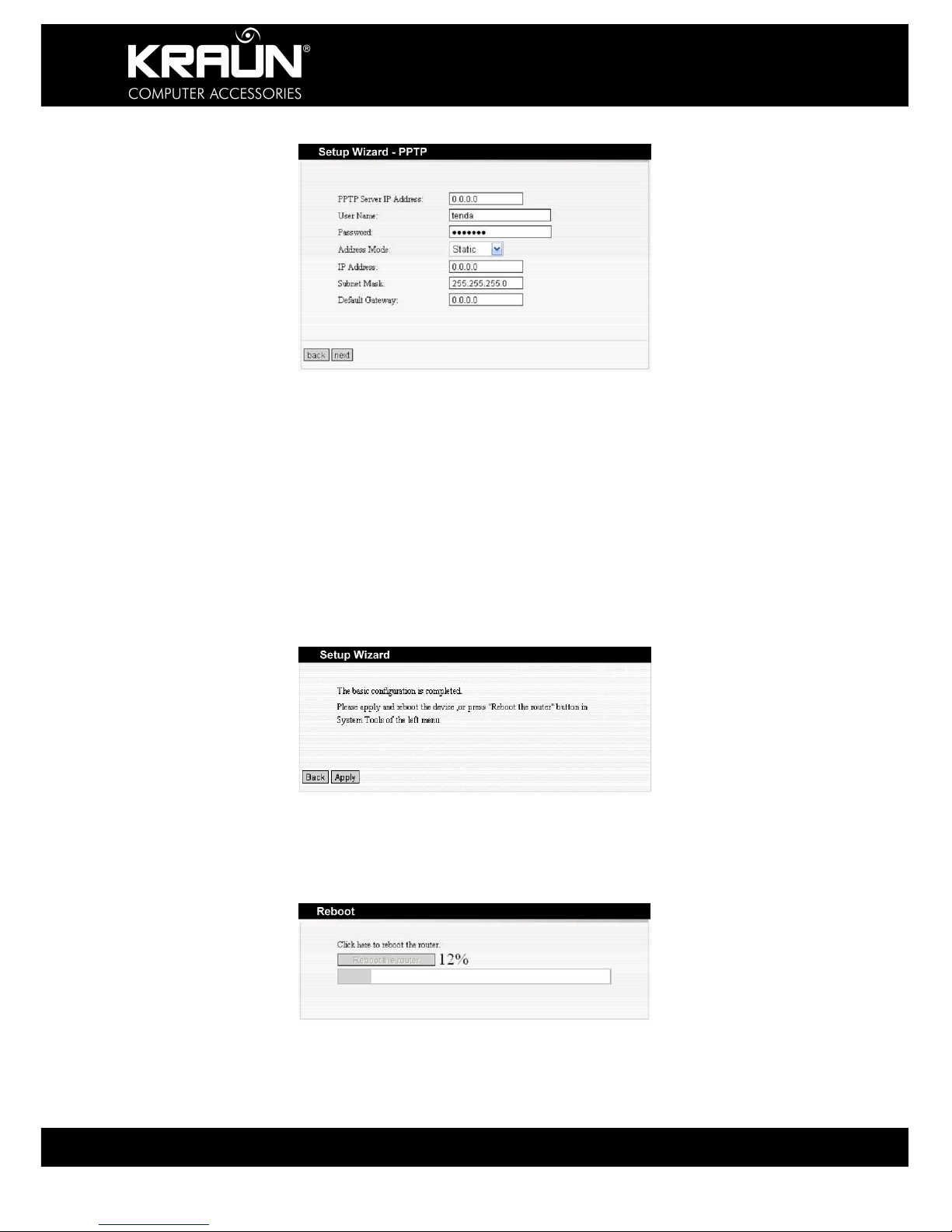
4.1.1.5 Connection Mode 5: PPTP
Enter the details provided by your ISP such as User Name, Password, and Server IP Address
etc.
PPTP provides two access modes.
Dynamic IP
Static IP
After entering all details, click “Next”.
4.1.2 Save Connection Settings
Once all details have been entered, click ‘Apply’.
4.1.3 Reboot and Connect
From the ‘System Tools’ options, select ‘Reboot’ to activate the settings and reboot the router.
Click ‘Reboot the Router’.
KR.2N
Wireless-N Broadband Router 300Mbps / 2T2R
15 www.kraun.it
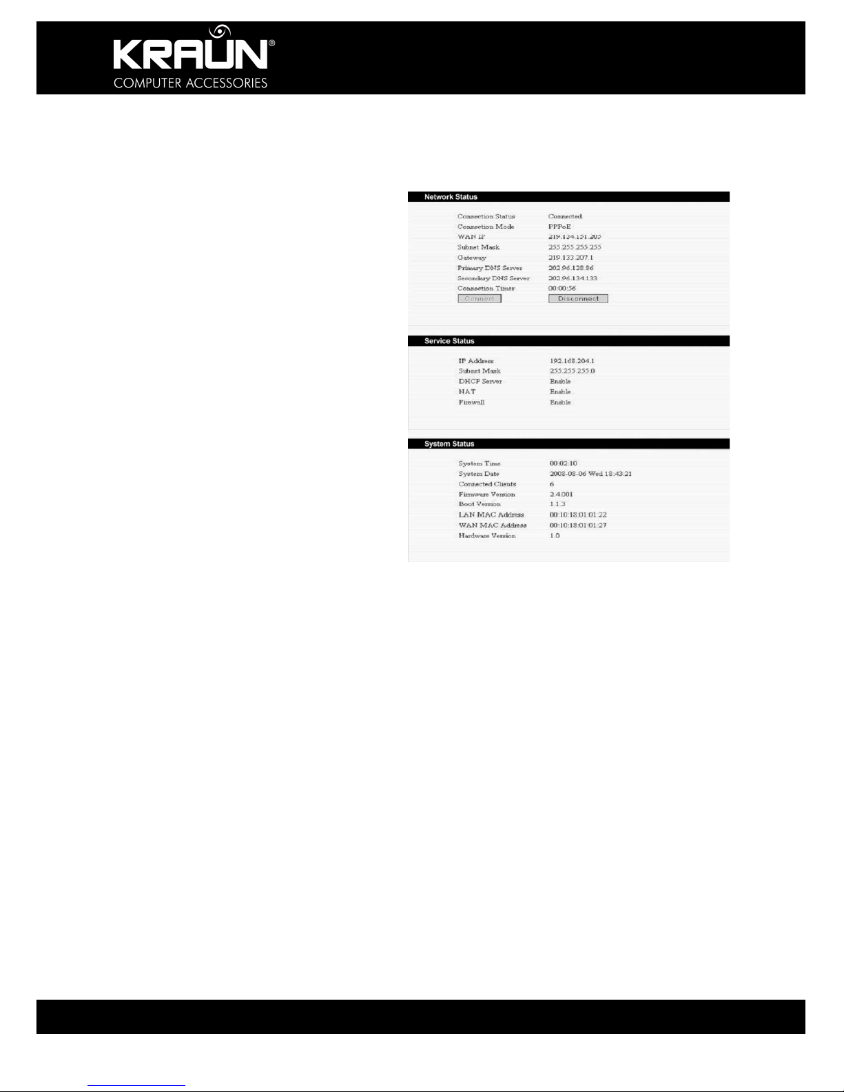
4.1.4 Check Connection Settings
After rebooting the Router, you may check the actual connection settings by selecting ‘System
Status’ from the menu of the configuration interface.
Network Status
Connection Status: Shows current
Connection Status, connected or
disconnected.
Connection Mode: If connected, shows
current Connection Method.
WAN IP: Current IP Address assigned to
the connection by your provider.
Subnet Mask: Current Subnet assigned to
the connection by your provider.
Gateway: Current Gateway IP Address
assigned to the connection by your
provider.
Primary DNS Server, Secondary DNS
Server: Current IP Address of DNS
Server(s) assigned to the connection by
your provider or entered manually.
Connection Timer: Connect time since last
restart.
Service Status
IP Address: The local IP address of the
Router (192.168.0.1 is default).
DHCP Server, NAT, Firewall: Shows
current status of these services, enabled or
disabled.
System Status
System Time: Current System Time of the
Router obtained either from the Internet or
set manually.
System Date: Current System Date of the
Router obtained either from the Internet or
set manually.
Connected Clients: Number of devices
connected to the Router.
Firmware Version, Boot Version,
Hardware Version: Current versions of
Hard and Firmware of the Router.
LAN MAC Address, WAN MAC Address:
Current MAC Addresses of the Router.

KR.2N
Wireless-N Broadband Router 300Mbps / 2T2R
16 www.kraun.it
Chapter 5::::Advanced Setting
This section provides details for advanced configuration of your Router. If you are not sure
about certain settings, we recommend using the default settings.
5.1 LAN Setting
MAC Address: The Router’s physical MAC address as seen on your local network. I cannot
be changed.
IP Address: The LAN IP Address of the Router (not your PC’s IP address). Once you modify
the IP address, you need to remember it for the Web-based Utility login. 192.168.0.1 is the
default value.
NOTE: If you have changed the IP address, you need use the new IP address
to login the Router Utility Web interface, and the default gateway setting of all
devices in the LAN must point to this IP Address to access the Internet.
Subnet Mask: The Router Subnet Mask is to determine the network size. 255.255.255.0 is
the default value.
5.2 MAC Address Clone
Some ISPs require end-user's MAC address to access their network. This feature copies the
MAC address of your network device to the Router. Enter the MAC address to be registered in
the MAC Address field, click “Apply” to clone the Address.
MAC Address: The MAC address to be registered with your ISP.
Clone MAC Address: Click to register your MAC Address
Restore Default MAC Address: Click to restore the default hardware MAC Address.
KR.2N
Wireless-N Broadband Router 300Mbps / 2T2R
17 www.kraun.it
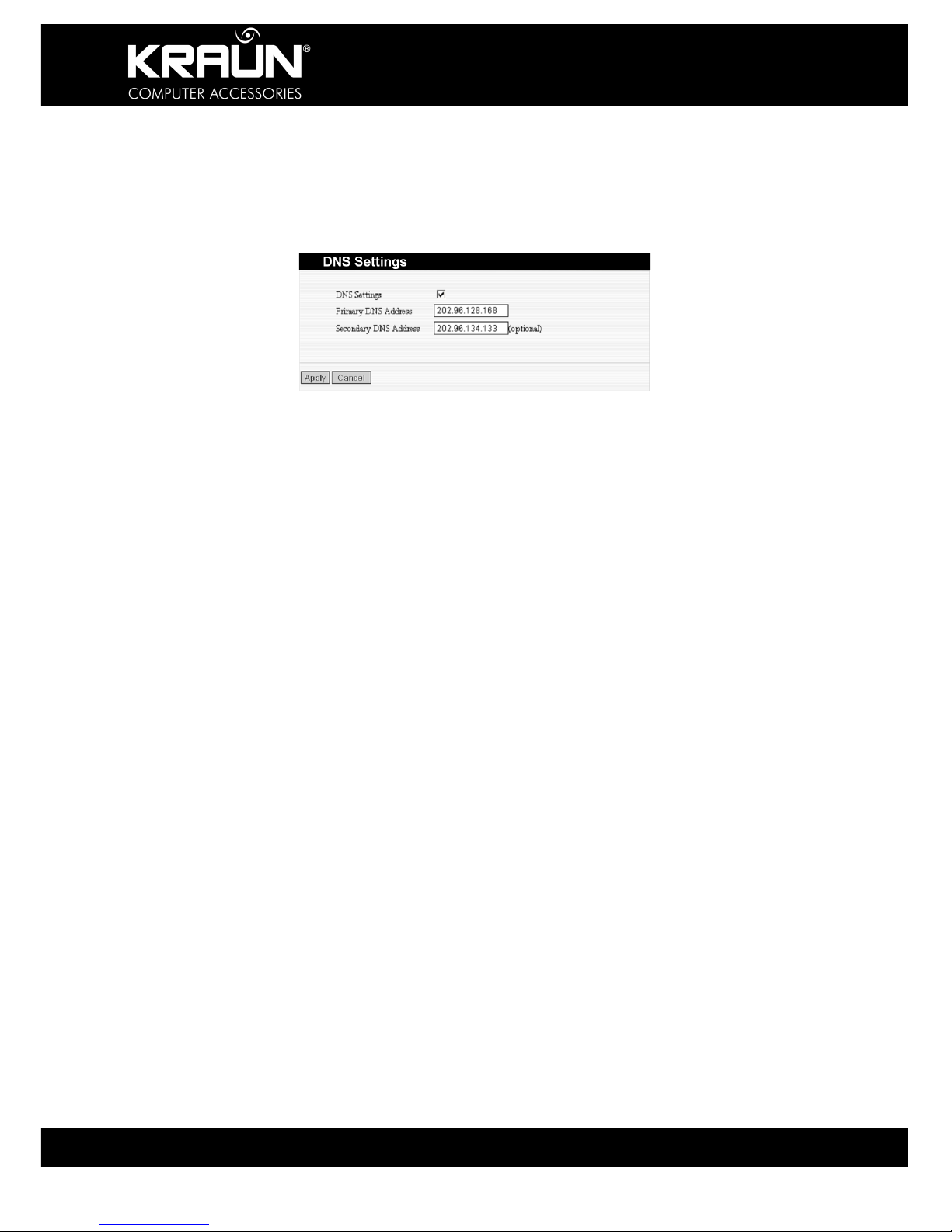
5.3 DNS Settings
DNS is short for Domain Name System (or Service), an Internet service that translates domain
names into IP addresses. Normally the IP Addresses of these servers are auto-assigned by
your ISP. If for whatever reasons your need to manually enter these addresses consult your
Internet Service Provider for details.
DNS Setting: Click the checkbox to enable the DNS server. The Router will forward DNS
requests to these servers.
Primary DNS Address: Enter the IP Address provided by your ISP.
Secondary DNS Address: Enter the IP Address provided by your ISP.
KR.2N
Wireless-N Broadband Router 300Mbps / 2T2R
18 www.kraun.it
5.4. WAN Settings
Select the connection method advised by your ISP.
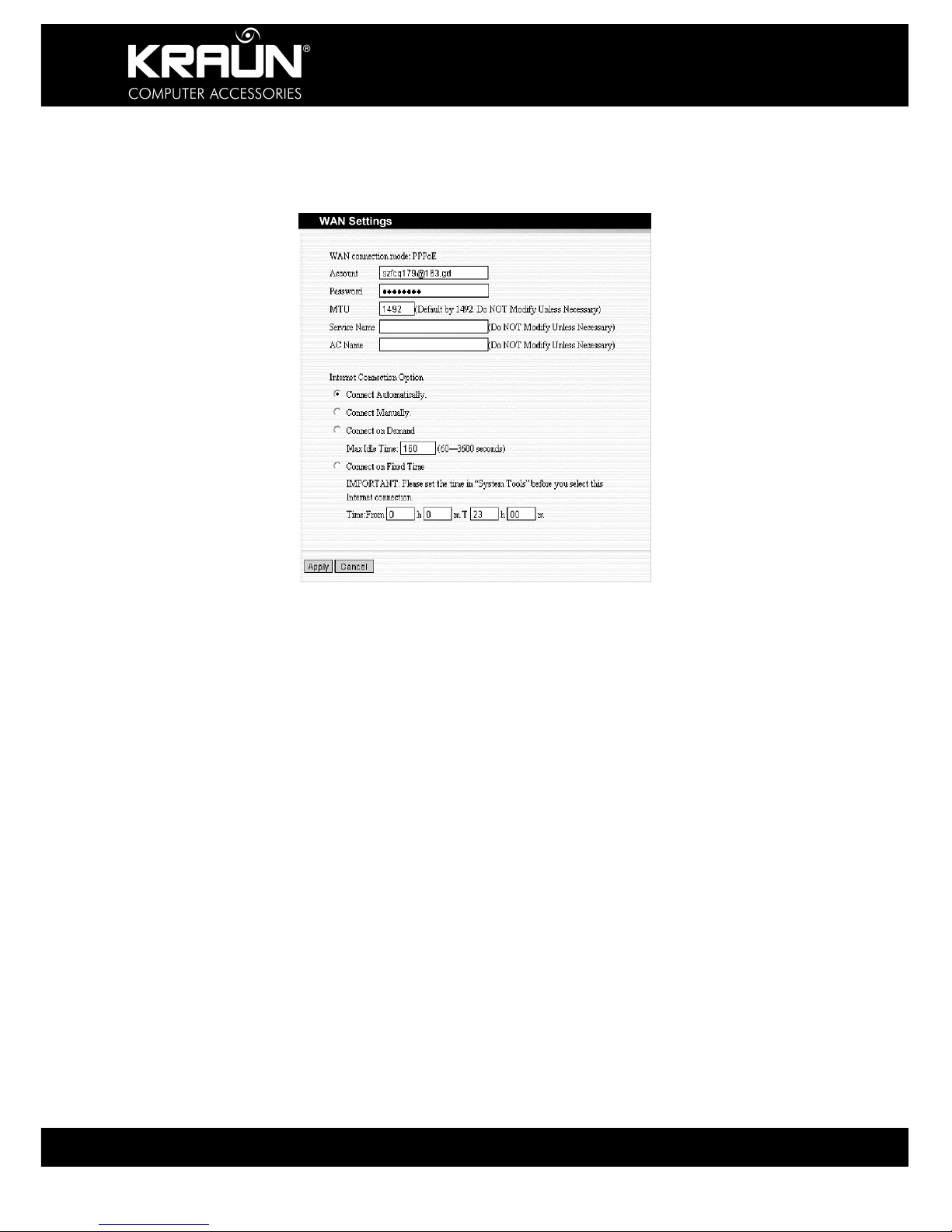
5.4.1 PPPoE
Account: Enter Account or User Name provided by your ISP.
Password: Enter the Password provided by your ISP.
MTU: Maximum Transmission Unit. It is the size of largest datagram that can be sent over a
network. The default value is 1492. Do NOT modify it unless necessary.
Service Name: It is defined as a set of characteristics that are applied to a PPPoE
connection. Enter it if provided. Do NOT modify it unless necessary.
AC Name: Enter it if provided. Do NOT modify it unless necessary.
Connect Automatically: Connect automatically to the Internet after rebooting the system or
connection failure.
Connect Manually: Connect to the Internet by the user manually.
Connect on Demand: Re-establish your connection to the Internet after the specific time
(Max Idle Time). Zero means you are always connected or else enter the time in minutes to
elapse before you want to disconnect from the Internet.
Connect on Fixed Time: Connect to the Internet during the time period specified.

KR.2N
Wireless-N Broadband Router 300Mbps / 2T2R
19 www.kraun.it
5.4.2 Static IP
IP Address: Here enter the WAN IP Address provided by your ISP.
Subnet Mask: Enter the WAN Subnet Mask here.
Gateway: Enter the WAN Gateway Address here.
Primary DNS Server: Enter the Primary DNS Server Address provided by your ISP.
Secondary DNS Server: Enter the Secondary DNS Server Address.
5.4.3 L2TP
L2TP Server IP: Enter the Server IP Address provided by your ISP.
User Name: Enter the L2TP User Name.
Password: Enter the L2TP Password.
MTU: Maximum Transmission Unit, you may need to change it for optimal performance with
your specific ISP. 1400 is the default MTU.
Address Mode: Select “Static” if your ISP supplies you with the IP address, Subnet Mask,
and Gateway Address. In most cases, select Dynamic.
IP Address: Enter the L2TP IP Address supplied by your ISP.
Subnet Mask: Enter the Subnet Mask supplied by your ISP.
Default Gateway: Enter the Default Gateway Address supplied by your ISP.

KR.2N
Wireless-N Broadband Router 300Mbps / 2T2R
20 www.kraun.it
5.4.4 PPTP
PPTP Server IP: Enter the Server IP Address provided by your ISP.
User Name: Enter the PPTP User Name provided by your ISP.
Password: Enter the PPTP Password provided by your ISP.
Address Mode: Select “Static” if your ISP supplies you with the IP address, Subnet Mask,
and Gateway Address. In most cases, select Dynamic.
IP Address: Enter the PPTP IP address supplied by your ISP.
Subnet Mask: Enter the Subnet Mask supplied by your ISP.
Default Gateway: Enter the Default Gateway supplied by your ISP.
5.5 WAN Medium
Select here the method to connect to the network.
a) Wired WAN: This is the default operating Mode.
Select this method if the Router is connected directly to the Internet Access Device, such as
xDSL modem and the Router should operate as a wireless access point for other wireless
devices to connect to

KR.2N
Wireless-N Broadband Router 300Mbps / 2T2R
21 www.kraun.it
b) Wireless WAN
Select this method if the Router acts as a wireless bridge to another wireless device
connected to the network. Click ‘Start Scan’ to select from available wireless networks. This
will automatically enter the SSID, MAC Address and Channel information. The Security Mode
and Encryption Algorithm, Password, Key etc. must be same as that of the device you want to
connect to, and must be entered manually.
5.6 Save Connection Settings
Once all details in either of the above configuration screens have been entered, click ‘Apply’.
The Router will check for any conflicting entries. If no errors are found, the Router will reboot
and attempt to connect to the Internet using the settings provided.

KR.2N
Wireless-N Broadband Router 300Mbps / 2T2R
22 www.kraun.it
Chapter 6::::Wireless Settings
This section mainly deals with the wireless settings, including Basic Settings, Security Setting,
Access Control and Advanced Settings.
6.1 Enable Wireless Mode
If not active, click “Enable” to start the Wireless Mode.
6.2 Basic Setting
Network Mode: Select one mode from the following: 802.11b/g mixed, 802.11b, 802.11g and
802.11b/g/n mixed.
Main SSID: Main SSID (Service Set Identifier) is the unique name of the wireless network.
This device has two SSID’s. The Main SSID is required.

KR.2N
Wireless-N Broadband Router 300Mbps / 2T2R
23 www.kraun.it
Minor SSID: Minor Service Set Identifier. It is optional.
Broadcast (SSID): Select “enable” to enable the device's SSID to be visible by wireless
clients.
Broadcast (SSID): If enabled, the SSID will be visible to other wireless devices.
BSSID: It is a 48bit identity used to identify a particular BSS (Basic Service Set) within an
area. In Infrastructure BSS networks, the BSSID is the MAC (Medium Access Control)
address of the AP.
Channel: Select the operating channel (from 1 to 14) of the wireless network.
Extension Channel: To increase data throughput of a wireless network, an extension channel
is used. This is only applicable in 11n mode.
Channel Bandwidth: Select channel bandwidth to improve wireless performance. If the
wireless network is 11b/g or 11n-compliant, select 40M, else select 20M.
6.3 Wireless Security Settings
Before configuring the Security settings, make sure that all connecting devices can support the
encryption and algorithm that you specify.
6.3.1 Mixed WEP
WEP (Wired Equivalent Privacy), a basic encryption method, usually encrypts wireless data
using a series of digital keys (64 bits or 128 bits in length). By using the same keys on each of
your wireless network devices, you can prevent unauthorized wireless devices from monitoring
your transmissions or using your wireless resources. WEP is based on RSA algorithm from
RC4. It is the original, but by current standards weak encryption method. We do not
recommend using this method.
If you need to use this method for compatibility reasons select ‘Mixed WEP’ to open the
following window:
SSID Choice: Select the SSID (main SSID or minor SSID) to configure security setting from
the drop-down menu.

KR.2N
Wireless-N Broadband Router 300Mbps / 2T2R
24 www.kraun.it
Security Mode: From the drop-down menu select the corresponding security encryption
modes.
WEP Key: Set the WEP key in either ASCII or Hex format.
Key Description: Enter ASCII code (5 or 13 ASCII characters. Illegal characters such as “/”,
“@”, “&”,”$” etc. are not allowed), or 10/26 Hex characters.
Default Key: Select one key from the four configured keys as the current available one.
6.3.2 WPA: Personal
WPA (Wi-Fi Protected Access), a Wi-Fi standard, is a more recent wireless encryption
scheme, designed to improve the security features of WEP. Select “WPA-personal” from the
drop-down menu to open the following window:
WPA Algorithms: Select one encryption type, AES or TKIP. (AES is stronger than TKIP.)
Pass Phrase: Enter the key, 8-63 ASCII characters in length.
Key Renewal Interval: Enter the key renewal period. It is to tell the Router how often to
change the keys.

KR.2N
Wireless-N Broadband Router 300Mbps / 2T2R
25 www.kraun.it
6.3.3 WPA2-Personal
WPA2 (Wi-Fi Protected Access version 2), It's more secure than Wired Equivalent Privacy
(WEP) and easy to set up.
WPA Algorithms: Select key Algorithms such as TKIP, AES and TKIP&AES.
Pass Phrase: Enter the key, 8-63 ASCII characters in length.
Key Renewal Interval: Enter the key renewal period. This will tell the Router how often to
change the keys.
6.3.4 WPA-Enterprise
This security mode is used when a RADIUS server is connected to the device. Select “WPAenterprise” from the drop-down menu to enter the following window:
Radius IP Address: Enter the IP Address of the Radius server.
Radius Port: Enter the authentication port of the Radius server. The default is 1812.
Shared Key: Enter the shared key of the authentication server with 8~63 ASCII characters.
Session Timeout: The authentication interval period between AP and authentication server.
The default is 3600s.

KR.2N
Wireless-N Broadband Router 300Mbps / 2T2R
26 www.kraun.it
6.3.5 WPA2-Enterprise
This security mode is also used when a RADIUS server is connected to the Router.
Radius IP Address: Enter the IP address of the Radius server.
Radius Port: Enter the authentication port of the Radius server. The default is 1812.
Shared Key: Enter the shared key for authentication server with 8~63 ASCII characters.
Session Timeout: The authentication interval period between AP and authentication server.
The default is 3600s.
KR.2N
Wireless-N Broadband Router 300Mbps / 2T2R
27 www.kraun.it
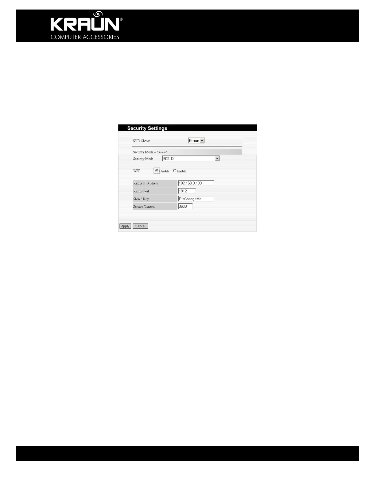
6.3.6 802.1X Authentication
This security mode is used when a RADIUS server is connected to the device. 802.1x, a kind
of Port-based authentication protocol, is an authentication type and strategy for users. The
port can be either a physical port or logic port (such as VLAN). For wireless LAN users, a port
is just a channel. The final purpose of 802.11x authentication is to check if the port can be
used. If the port is authenticated successfully, you can open this port, allowing all data to pass.
If the port is not authenticated successfully, you can keep this port “disabled” which allows
only 802.1x authentication protocol message to pass. Select “802.1x” from the drop-down
menu to open the following window:
WEP: Click “Enable/Disable” to enable or disable the WEP algorithm.
Radius IP Address: Enter the IP address of the Radius server.
Radius Port: Enter the authentication port of the Radius server. The default is 1812.
Shared Key: Enter the shared key for authentication server with 8~63 ASCII characters.
Session Timeout: The authentication interval period between AP and authentication server.
The default is 3600s.
NOTE:
To improve security, do not use those passwords, which can be found
in a dictionary or are easy to guess! Wireless clients will remember the
WEP key, so you only have to input the WEP key on wireless clients
once, and it is worth to use complicated WEP key to improve security.

KR.2N
Wireless-N Broadband Router 300Mbps / 2T2R
28 www.kraun.it
6.4 WPS Setting
WPS (Wi-Fi Protected Setting) can be easy and quick to establish the connection between the
wireless network clients and the Router through encrypted contents. You only need to enter
the PIN code to configure without selecting encryption method and entering secret keys. The
magic happens automatically between WPS compliant devices.
WPS Setting: Enable or disable the WPS function. This function is disabled by default.
WPS Mode: Supports two ways to configure WPS settings: PBC (Push-Button Configuration)
and PIN code.
PBC: Select PBC or press the WPS button on the front panel of the device for one second
(Press the button for one second and WPS indicator will be blinking for 2 minutes, which
means the WPS is enabled. During that time, you may enable other devices to start WPS/PBC
negotiation with the Router. WPS only supports up to 32 clients. After two minutes, the WPS
indicator will switch off. If more clients need to be added, repeat the above steps).
PIN: If this option is enabled, you need to enter a wireless client PIN code in the field and keep
the same code in the client.
WPS Summary: Show Wi-Fi current protection state, authentication mode, encryption
method, etc.
Note: Press the WPS/Reset button for 1 second on the front panel to run PBC.
Press for 7 seconds, the device’s setting will restore to default setting. The
access client has to support WPS function when you implement WPS
settings.

KR.2N
Wireless-N Broadband Router 300Mbps / 2T2R
29 www.kraun.it
6.5 WDS Setting
WDS (Wireless Distribution System) can be used to expand your current wireless network
coverage. The Router supports three modes: Lazy, Bridge and Repeater.
Lazy: In this mode, the connected wireless device should be in Bridge or Repeater mode, and
select the Router BSSID to implement wireless connection.
Bridge: In this mode, you may connect two or more wired networks via wireless signals. In
this mode, you need add the Wireless MAC address of the connecting device into the Router's
AP MAC address table or select one from the scanning table.
Repeater: In this mode, you need add the MAC address of the connecting device into the
Router's AP MAC address table to amplify and repeat wireless signals. All devices in a
repeater setup must support WDS functionality.
Encrypt Type: You may select WEP mode, TKIP mode, and AES mode for security here.
Key: Enter the encryption key or pass phrase for the connecting devices.
AP MAC Address: Enter the MAC address of the connected wireless device.
NOTE: Two wireless routers must use the same band, channel number, and
security settings!

KR.2N
Wireless-N Broadband Router 300Mbps / 2T2R
30 www.kraun.it
6.6 Advanced Wireless Setting
This section provides information to configure the advanced wireless settings of the Router,
including the Radio Preamble, 802.11g/n Rate, Fragmentation Threshold, RTS Threshold,
Beacon Period and DTIM Interval. If you do not know what they mean, we recommend that
you use the default settings.
BG Protection Mode: Try different settings if you have problems connecting 11b/g wireless
clients with the Router running in 11n wireless mode. The default is “Auto”.
Basic Data Rates: In term of different requirements, you can select one of the suitable Basic
Data Rates from the drop-down menu. Here, default value is (1-2-5.5-11Mbps…).
Beacon Interval: The frequency interval of the beacon, which is a packet broadcast by a
router to synchronize a wireless network. The default value is 100 ms. It is recommended not
to modify the default value.
Fragmentation Threshold: The fragmentation threshold defines the maximum transmission
packet size in bytes. The packet will be fragmented if the arrival is bigger than the threshold
setting. The default size is 2346 bytes.
RTS Threshold: RTS stands for “Request to Send”. This parameter controls what size data
packet the frequency protocol issues to RTS packet. If the device works in SoHo, do not
modify the default value.
TX Power: Set the wireless output power level. The default value is 100.
WMM Capable: To enhance wireless multimedia transfer performance (0n-line video and
voice). If you are not clear about this, enable it.
APSD Capable: It is used for auto power-saved service. The default is disabled.

KR.2N
Wireless-N Broadband Router 300Mbps / 2T2R
31 www.kraun.it
6.7 Wireless Access Control
To secure your wireless LAN, the wireless access control is actually based on the MAC
address management. Select “Wireless Setting: Access Control” to open the following window:
MAC Address Filter: Enable/disable MAC address filter. “Block” to prevent the MAC
addresses in the list from accessing the wireless network. “Allow” to permit the MAC address
in the list to access the wireless network.
MAC Address Management: Enter the MAC address to implement the filter policy. Click
“Add” to finish the MAC adding operation.
MAC Address List: Show the MAC addresses of the devices in the list. You may add or
delete any them.
6.8 Wireless Connection Status
This page is to show the current wireless access status. Click “Refresh” to update the wireless
connection information.
MAC Address: Shows MAC address of the connected devices.
Bandwidth Shows the channel bandwidth of connected devices.

KR.2N
Wireless-N Broadband Router 300Mbps / 2T2R
32 www.kraun.it
Chapter 7: DHCP Server
7.1 DHCP Server Setting
If enabled, the DHCP (Dynamic Host Control Protocol) Server will assign an IP Address to
devices on the LAN / Private Network that do not have a fixed IP Address assigned to them.
For that purpose an address pool needs to be specified to make sure that there will be no
address collisions. Devices connecting to this address pool must be configured to “Obtain an
IP Address Automatically”. Specifying the starting and ending address of the IP Address pool
is required.
DHCP Server: Activate the checkbox to enable server.
IP Address Start/End: Enter the range of IP Addresses for DHCP server assignment.
Lease Time: The time length of the IP address lease.
For example: set the lease time as one hour. Then the DHCP server will
recycle and assign the IP address again.
7.2 DHCP Client List
Static IP assignment allows adding a specific IP Address to the assigned MAC address.
IP Address: Enter one IP address for the computer on the LAN network.
MAC Address: Enter the MAC address of the computer you want to assign the above IP
address. Click “Add” to add the entry in the list.
Hostname: The name of the computer that is assigned a fixed IP Address.
Lease Time: The time length of the corresponding IP address lease.

KR.2N
Wireless-N Broadband Router 300Mbps / 2T2R
33 www.kraun.it
Chapter 8::::Virtual Server
8.1 Single Port Forwarding
The Router can be configured as a virtual server for local services behind the LAN port.
Remote requests will be re-directed to the local servers via the virtual server. This section
allows you to configure single port forwarding. Single Port Forwarding allows you to set up
public services such as web servers, ftp, e-mail and other specialized Internet applications on
your network.
External Port: This is the external port number for server or Internet application, for example,
port 21 for ftp service.
Internal Port: This is the port number of LAN computer set by the Router. The Internet traffic
from the external port will forward to the internal port. For example, you can set the internal
port NO.66 to act as the external port NO.21 for ftp service.
IP Address: Enter the IP address of the PC where you want to set the applications.
Protocol: Select the protocol (TCP/UDP/Both) for the application.
Enable: Click this option to enable this rule.
Delete: Click the check box and then click ‘Apply’ to delete the selected rule.

KR.2N
Wireless-N Broadband Router 300Mbps / 2T2R
34 www.kraun.it
The ‘Well-known Service Port’ drop-down menu lists the common ports. You may select one
and add it to the ID from the ID drop-down menu. Click “Add” to add the port in the above
table. If the port you wish to enter is not available from the Drop-down selection, you may
enter it manually.
Add – Click to add the well-know port to the ID you selected.
In the above screen, a request arriving at external port 40 would be redirected to port
80 of the device located at 192.168.0.10.
NOTE: If you set a virtual server at service port 80, you must set the Web management
port on the Remote Web Management page to a port other than 80, such as
8080, else you will not be able to access the configuration page remotely.
8.2 Port Range Forwarding
The Router can be configured as a virtual server for local services behind the LAN port.
Remote requests will be re-directed to the local servers via the virtual server. This section
allows you to configure port range forwarding. Port Range Forwarding allows you to set up
public services such as web servers, ftp, e-mail and other specialized Internet applications that
require ranges of ports to be accessible on your network.
Start/End Port: Enter the start/end port numbers of the ranges of External ports to be opened
for services or Internet applications.
IP Address: Enter the IP address of the device to which you want the external request
forwarded to.
Protocol: Select the protocol (TCP/UDP/Both) for the application or service.

KR.2N
Wireless-N Broadband Router 300Mbps / 2T2R
35 www.kraun.it
Well-Known Service Port: Select the well-known services as DNS, FTP from the drop-down
menu to add to the configured one above.
Delete: Click the check box and then click ‘Apply’ to delete the selected rule.
The ‘Well-known Service Port’ drop-down menu lists the common ports. You may select one
and add it to the ID from the ID drop-down menu. Click “Add” to add the port in the above
table. If the port you wish to enter is not available from the Drop-down selection, you may
enter it manually.
Add – Click to add the well-know port to the ID you selected.
In the above screen, a request arriving at external ports 4600 to 4670 would be
redirected to ports 4600 to 4670 of the device located at 192.168.0.10.
NOTE: If you set a virtual server at service port 80, you must set the Web management
port on the Remote Web Management page to a port other than 80, such as
8080, else you will not be able to access the configuration page remotely.
8.3 Port Trigger Setting
When internal clients have access to external servers in the Internet for some applications
such as games, the client request to connect with the severs will trigger certain ports to be
opened allowing communication between client and server so long as the client is active and
vice versa. In the default setting, the Router will refuse to accept any request from WAN,
which will bring communication halt. The port triggering is used to define triggering rules.
IP Range: The internal IP address range for requesting external server application.
Trigger Port: The port range through which the internal clients send requests to external
servers within the range of 1-65535.
External Port: The port range through which the external server sends requests to internal
clients within the range of 1-65535.

KR.2N
Wireless-N Broadband Router 300Mbps / 2T2R
36 www.kraun.it
Add: After edit the rule, click the “Add” button to add the current entry to port triggering list.
Apply: Click “Apply” to activate the current rule.
Cancel: Click “Cancel” to drop all setting saved last time.
Note: The special application can be only used on one PC. If there is more than one
PC to open the same triggering port, the external port will be connected to the
last device requesting the application.
8.4 ALG Service Setting
ALG (Application Layer Gateway), in the context of computer networking, consists of a
security component that augments a firewall or NAT employed in a computer network. It
allows customized NAT traversal filters to be plugged into the gateway to support address and
port translation for certain application layer "control/data" protocols such as FTP, Bit Torrent,
SIP, RTSP, file transfer applications etc.
In order for these protocols to work through NAT or a firewall, either the application has to
know about an address/port number combination that allows incoming packets, or the NAT
has to monitor the control traffic and open up port mappings (firewall pinhole) dynamically as
required. Legitimate application data can thus be passed through the security checks of the
firewall or NAT that would have otherwise restricted the traffic for not meeting its limited filter
criteria.
Usually allowing client applications to use dynamic ephemeral TCP/ UDP ports to
communicate with the known ports used by the server applications, even though a firewallconfiguration may allow only a limited number of known ports. In the absence of an ALG,
either the ports would get blocked or the network administrator would need to explicitly open
up a large number of ports in the firewall; rendering the network vulnerable to attacks on those
ports.
In the default ALG settings, the following protocols have enabled. It is recommended to keep
the settings unchanged.
1, FTP
2, TFTP
3, PPTP
4, IPSec
5, L2TP

KR.2N
Wireless-N Broadband Router 300Mbps / 2T2R
37 www.kraun.it
8.5 DMZ Host
The DMZ function is to allow one computer in LAN to be exposed to the Internet for a specialpurpose service as Internet gaming or videoconferencing.
DMZ Host IP Address: The IP address of the computer you want to expose.
Enable: Click the checkbox to enable the DMZ host.
IMPORTANT: The Device placed in the DMZ is completely exposed to the
Internet and there is no Firewall protection. Please make sure your have
alternative security precautions in place before moving a PC or other network
device into the DMZ.
8.6 UPnP Setting
Your Router supports the latest Universal Plug and Play functionality. This functionality is
available with Windows XP or devices or software that supports UPnP. With the UPnP
function a host in the LAN can request the router to process some special port switching so as
to enable a host outside to visit the resources in the internal host.
Enable UPnP: Click the checkbox to enable UPnP functionality.

KR.2N
Wireless-N Broadband Router 300Mbps / 2T2R
38 www.kraun.it
Chapter 9: Traffic Control
Traffic control, also known as QoS (Quality of Service) is used to limit communication speed in
the LAN and WAN. Up to 20 entries can support speed control for up to 254 network devices,
such as PC’s, VoIP Phones, Web Cameras etc., including IP Address range configurations.
Enable Traffic Control: Click to enable or disable the internal IP bandwidth control.
Interface: To limit the upload / download bandwidth in WAN port.
Service: Select the service to be controlled, such as HTTP or FTP service.
IP Starting Address: The first IP Address of devices under traffic control.
IP Ending Address: The last IP Address of devices under traffic control.
Uploading/Downloading: Specify the traffic direction for the selected IP Addresses, Upload
or Download.
Bandwidth: Specify the upload / download minimum / maximum speed (KB/s). Note that the
accumulated bandwidth settings cannot exceed your connection speed
Apply: Click to enable the current rule.
Add: After entering a rule, click the “Add” button to add his entry to the current rule list.
Save: Click “Save” to activate the current rule.
Cancel: Click “Cancel” to drop all changes since last “Save”.
KR.2N
Wireless-N Broadband Router 300Mbps / 2T2R
39 www.kraun.it
Chapter 10: Security Setting
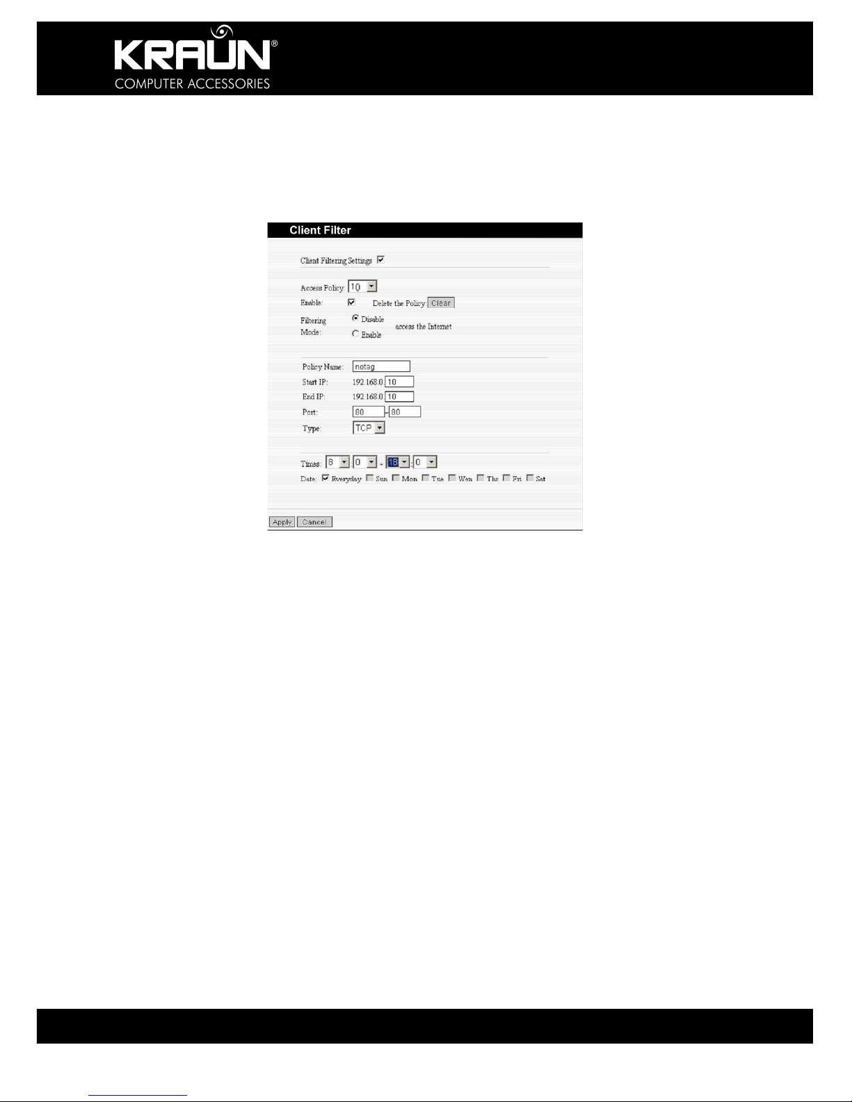
10.1 Client Filter Settings
For finer grained configuration of your network setup, the Packet Filter Function allows control
over which ports can access the Internet.
Client Filter: Check to enable client filter.
Access Policy: Select a policy from the drop-down menu.
Enable: Check to enable the access policy.
Clear the Policy: Click “Clear” button to clear all settings for the policy.
Filter Mode: Click one radio button to enable or disable to access the Internet.
Policy Name: Enter a name for the access policy selected.
IP Start/End: Enter the starting/ending IP Address.
Port No.: Enter the port range based on the protocol for access policy.
Protocol: Select one protocol (TCP/UDP/Both) from the drop-down menu.
Time: Select the time range for the filter selected.
Days: Select the day(s) to run the access policy.
Example: The above setting will disable Internet access for a device or PC at IP Address
192.168.0.10 everyday from 08:00h to 18:00h.

KR.2N
Wireless-N Broadband Router 300Mbps / 2T2R
40 www.kraun.it
10.2 URL Filter
In order to control the access of devices in your network to the Internet, you may use URL
filtering to allow or restrict such access.
URL Filter: Check to enable URL filter.
Access Policy: Select an entry from previously entered policies from the drop-down menu.
Enable: Check to enable the access policy.
Filter Mode: Click the appropriate radio button to enable or disable an access policy.
Policy Name: Enter a name for the access policy selected.
Start/End IP: Enter the starting/ending IP address for the policy.
URL Strings: Specify text strings or keywords in the DNS field. If any part of the URL contains
these strings or words, the web page will not be accessible display.
Time: Select the time range applicable to the policy being entered / edited.
Days: Select the weekdays applicable to the policy being entered / edited.
Apply: Click to apply the settings.
Example: The above setting will disable Internet access for a device or PC at IP Address
192.168.0.10 at any time, if the address, or part thereof, entered in the DNS contains the
letters ‘xxx’.
KR.2N
Wireless-N Broadband Router 300Mbps / 2T2R
41 www.kraun.it
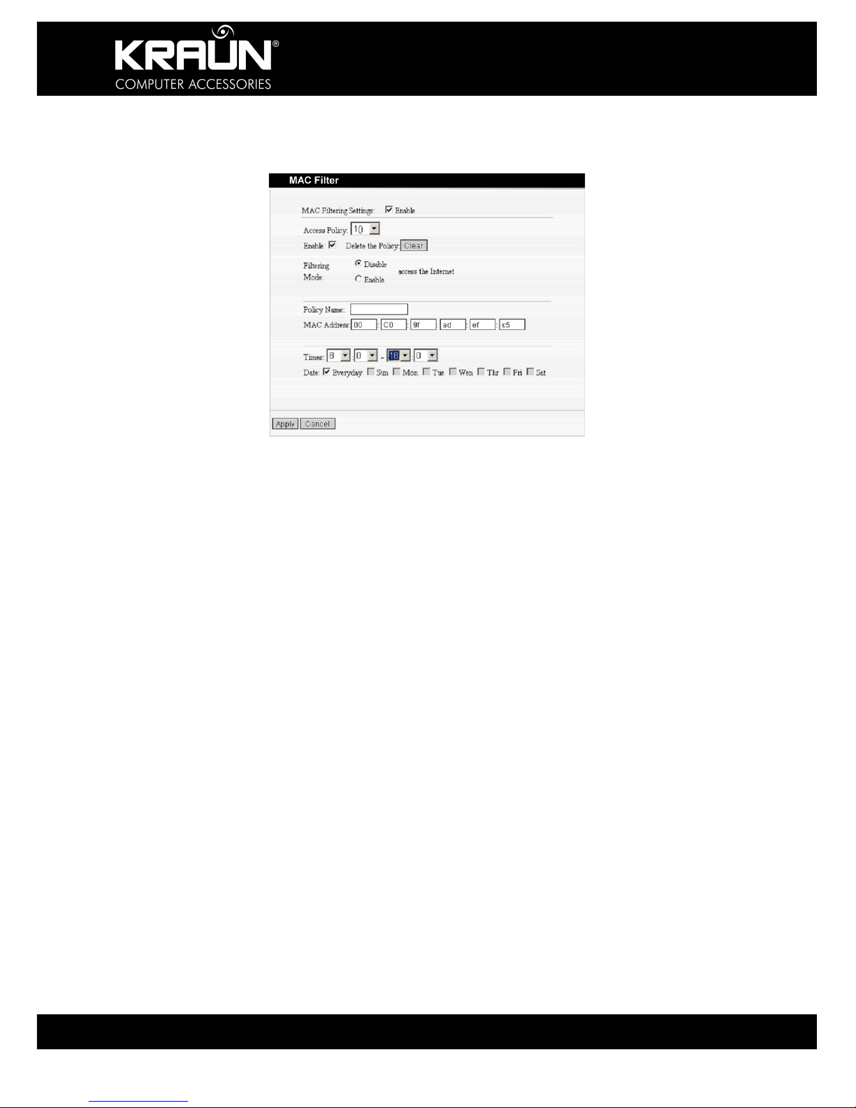
10.3 MAC Address Filter
In order to manage the computers in LAN better and to preserve resources you may use the
MAC Filter to control Internet access.
MAC Address Filter: Check to enable MAC address filter.
Access Policy: Select an entry from previously entered policies from the drop-down menu.
Enable: Check to enable the access policy.
Filter Mode: Click one radio button to enable or disable to access the Internet.
Policy Name: Enter a name for the access policy selected.
MAC Address: Enter the MAC address of the device to which this policy applies.
Time: Select the time range applicable to the policy being entered / edited.
Days: Select the weekdays applicable to the policy being entered / edited.
Apply: Click to apply the settings.
Example: The above setting will disable Internet access for a device or with MAC Address
00:C0:9F:AD:FF:C5 from 08:00h –18:00h

KR.2N
Wireless-N Broadband Router 300Mbps / 2T2R
42 www.kraun.it
10.4 Prevent Network Attack
This setting allows you to protect the internal network from exotic attack such as SYN Flooding
attack, Smurf attack, LAND attack, etc. Once detecting such an attack, the Router will restrict
the available bandwidth automatically. The IP Address of the attacker will be registered in the
“System Log”, if it is enabled.
Prevent Network Attack: Check to enable network attack prevention.
10.5 Remote Web Management
This option allows the network administrator to manage the Router remotely. If you need to
access the Router from outside the local network, please select the “Enable” and enter an
address or address range from which to permit such access.
Enable: Check to enable remote web management.
Port: The management port open to outside access. The default value is 80.
WAN IP Address: Specify the range of the WAN IP address for remote management.
Note: If you want to login to the device through port 8080, you need use the format of
‘WAN IP address:port’.
Example: http://219.134.32.101:8080/
If the WAN IP address range starts and ends with 0.0.0.0 access is enabled for any external
IP Address. If you enter addresses in the WAN IP Address fields like 218.88.93.33 -
218.88.93.35, then only the IP Addresses 218.88.93.33, 218.88.93.34 and 218.88.93.35 can
access the Router.
CAUTION: We do not recommend enabling this option, as it will make the
Management Web Interface of your Router accessible from the Internet.
KR.2N
Wireless-N Broadband Router 300Mbps / 2T2R
43 www.kraun.it
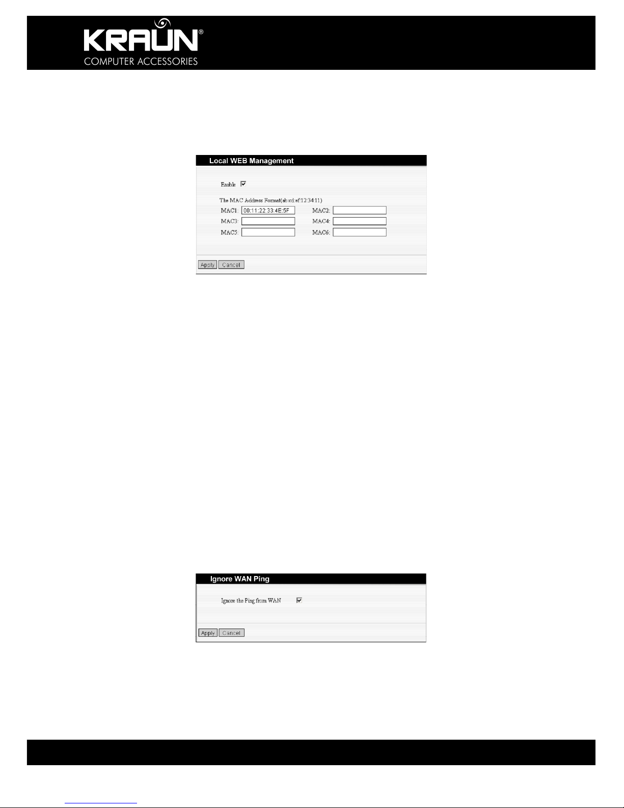
10.6 Local Web Management
Local web management, the alternative to remote web management, is to allow the network
administrator to manage the Router in LAN. Any PC in the LAN can access the Web
management utility by default. To restrict access, you may enter the specific MAC address of
PC’s (up to 6) in the LAN, permitted to access the Administration Interface.
Enable: Check to enable the local web management interface
MAC1 – 6: Enter the MAC addresses of LAN devices allowed to perform management
functions.
Note:
1. In the he default setting this option is un-checked. All computers in the LAN
can login to the management interface.
2. If you want to restrict access to the management interface, check ‘Enabled’
and enter the MAC Addresses (up to 6) of the devices that are permitted to
access the management interface.
4. If you check ‘Enabled’ and leave all MAC Address fields blank, the
management interface will not be accessible by ant device in the network.
10.7 WAN Ping
The ping test is to check the status of your Internet connection. When disabling the test, the
system will ignore the ping test from WAN.
Ignore Ping from WAN: Check to ignore ping requests and give no reply.
KR.2N
Wireless-N Broadband Router 300Mbps / 2T2R
44 www.kraun.it
Chapter 11: Routing Setting
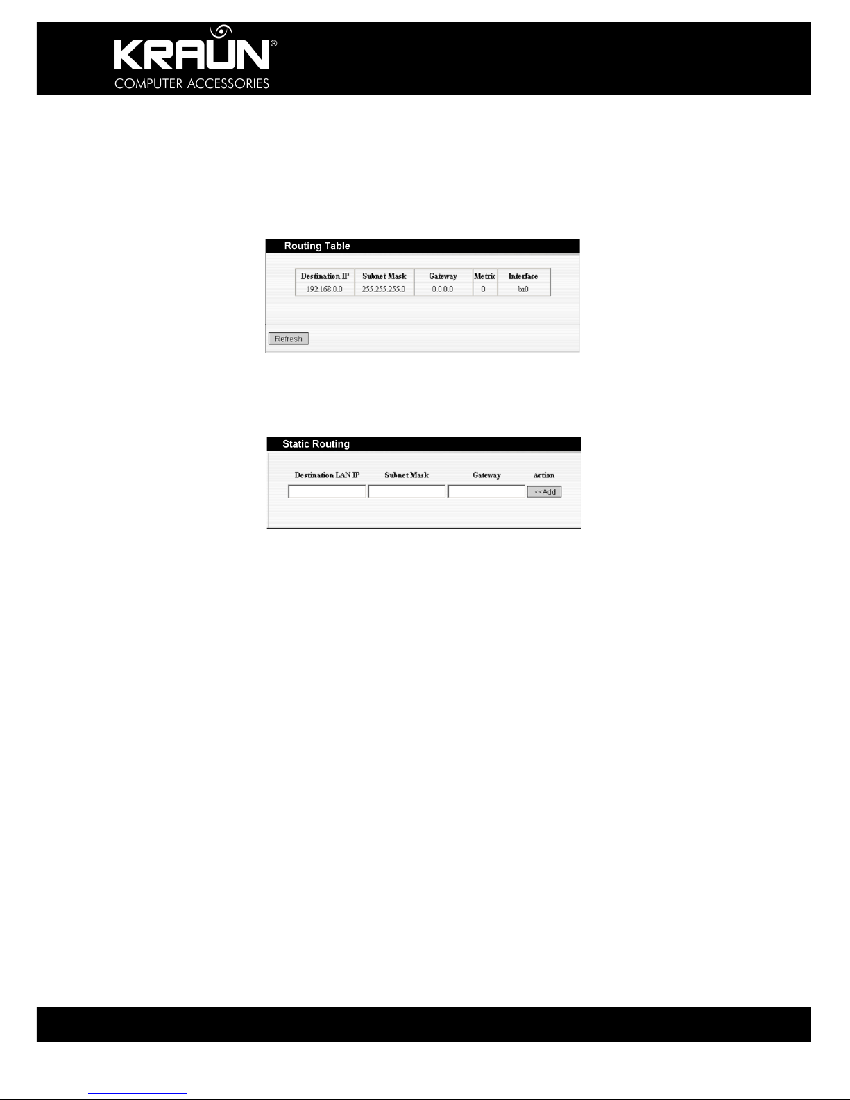
11.1 Routing Table
The main purpose of a router is to look for the best path for every data frame, and transfer this
data frame to a destination. The routing table stores the routes and metrics associated with
those routes to particular network destinations.
11.2 Static Routing
This page is used to enter static routing information.
Destination LAN IP: The address of the remote host to a static route is to be constructed.
Subnet Mask: The network portion of the Destination LAN IP.
Gateway: The gateway of the next hop, usually the Router or IP address of the host.
Note:
1. The gateway must be in the same segment as the LAN IP address of the
Router.
2. If the destination IP address is the IP Address of one host, the Subnet Mask
should be 255.255.255.255.
3. If the destination IP address is an IP address range, the subnet mask should
match the IP address. For example, if the IP is 10.0.0.0, subnet mask should
be 255.0.0.0; if the IP is 10.1.2.0, subnet mask should be 255.255.255.0.

KR.2N
Wireless-N Broadband Router 300Mbps / 2T2R
45 www.kraun.it
Chapter 12: System Tools
12.1 Time Setting
This option allows you to select the time zone for your location. If you turn off the Router, the
settings for time are not maintained. However, the Router will automatically obtain the GMT
time again once it has access to the Internet.
Time Zone: Select the Time Zone for your location from the drop-down menu.
Customized time: Enter Date and Time manually, or if you are located in a non-standard time
zone.
Note: When the Router is powered off, the time setting will be lost. Before the Router
will obtain GMT time automatically, you need to connect with the Internet and
obtain the GMT time, or set the time manually on this page first.
A valid time setting must be available for access control functions to be
effective.

KR.2N
Wireless-N Broadband Router 300Mbps / 2T2R
46 www.kraun.it
12.2 DDNS
The DDNS (Dynamic Domain Name System) is supported by this Router. It will allow you to
assign a fixed host and domain name to a dynamic Internet IP address so that they will be
accessible from the Internet. If enabled, the Router will send an update to the DDNS provider
whenever an external IP Address change is recognized. You need to have an account with
one of the DDNS providers before you can use this function.
DDNS: Click the radio button to enable or disable the DDNS service.
Service Provider: Select one from the drop-down menu and press “Sign up” for registration.
User Name: Enter the user name the same as the registration name.
Password: Enter the password you set.
Domain Name: Enter the domain name you registered.
12.3 Backup / Restore Settings
The Router configuration can be saved to a file on your PC for use in the event of a system
failure. That file may also be used to restore the settings in case the Router has become
inoperative as a result of mis-configuration.
Select a Directory or Folder and enter a file name that you can remember

KR.2N
Wireless-N Broadband Router 300Mbps / 2T2R
47 www.kraun.it
Backup Setting: Click “Backup” to backup and save the Router settings.
Restore Setting: Click “Browse” button to select the backup files.
Click “Restore” button to restore previous settings.
KR.2N
Wireless-N Broadband Router 300Mbps / 2T2R
48 www.kraun.it
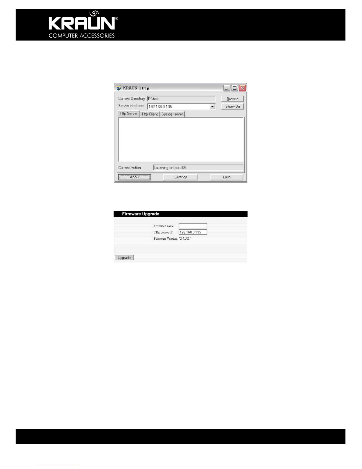
12.4 Firmware Upgrade
The Router provides the firmware upgrade by clicking the “Upgrade” after browsing to the
firmware upgrade packet. Updates, if available, can be downloaded from www.kraun.it After
the upgrade is completed, the Router will reboot automatically.
If the update file is in a compressed format (rar, zip) un-compress it first before uploading to
the Router.
When your computer connects with the Router’s LAN port, and obtain the IP address assigned
by the Router, please run the TFTP Server, and keep the “Firmware File Name” same with the
upgrade file name. Click “Upgrade” to start the firmware upgrading.
IMPORTANT: Do not power off the system during the firmware upgrade to avoid
damaging the device. The Router will reboot after the upgrade.

KR.2N
Wireless-N Broadband Router 300Mbps / 2T2R
49 www.kraun.it
12.5 Restore to Factory Default Settings
This button is to reset all settings to the default values. It means the Router will lose all the
settings you have set. So please Note down the related settings if necessary.
Restore: Click this button to restore to default settings.
Factory Default Settings:
User Name: admin
Password: admin
IP Address: 192.168.0.1
Subnet Mask: 255.255.255.0
NOTE: After restoring to factory default settings, please restart the device to
activate the default settings.
12.6 Reboot
Rebooting the Router makes the settings configured go into effect or to set the Router again if
setting failure happens.
Reboot the router: Click this button to reboot the device.

KR.2N
Wireless-N Broadband Router 300Mbps / 2T2R
50 www.kraun.it
12.7 Password Change
This section is to set a new user name and password to better secure your router and
network.
User Name: Enter a new user name for the device.
Old Password: Enter the old password.
New Password: Enter a new password.
Re-enter to Confirm: Re-enter to confirm the new password.
NOTE: It is highly recommended to change the password to secure your network
and the Router.
12.8 System Log
The function allows you to view the system log. Click the “Refresh” button to update the log.
Click “Clear” to clear all shown information. If the log is longer than 150 records, it will clear
them automatically.
Refresh: Click this button to update the log.
Clear: Click this button to clear the current shown log.

KR.2N
Wireless-N Broadband Router 300Mbps / 2T2R
51 www.kraun.it
Appendix I: Glossary
Access Point (AP): Any entity that has station functionality and provides access to the
distribution services, via the wireless medium (WM) for associated
stations.
Channel: An instance of medium use for the purpose of passing protocol data
units (PDU’s) that may be used simultaneously, in the same volume of
space, with other instances of medium use (on other channels) by
other instances of the same physical layer (PHY), with an acceptably
low frame error ratio (FER) due to mutual interference.
SSID: Service Set identifier. An SSID is the network name shared by all
devices in a wireless network. Your network’s SSID should be unique
to your network and identical for all devices within the network. It is
case-sensitive and must not exceed 20 characters (use any of the
characters on the keyboard). Make sure this setting is the same for all
devices in your wireless network.
WEP: Wired Equivalent Privacy (WEP) is a method for secure wireless data
transmission. WEP adds data encryption to every single packet
transmitted in the wireless network. The 40bit and 64bit encryption are
the same because of out 64 bits, 40 bits are private. Conversely, 104
and 128 bit is the same. WEP uses a common KEY to encode the
data. Therefore, all devices on a wireless network must use the same
key and same type of encryption. There are 2 methods for entering the
KEY; one is to enter a 16-bit HEX digit. Using this method, users must
enter a 10-digit number (for 64-bit) or 26-digit number (for 128-bit) in
the KEY field. Users must select the same key number for all devices.
The other method is to enter a text and let the computer generate the
WEP key for you. However, since each product use different method
for key generation, it might not work for different products. Therefore, it
is NOT recommend using.
WPA/WPA2: A security protocol for wireless networks that build on the basic
foundations of WEP. It secures wireless data transmission by using a
key similar to WEP, but the added strength of WPA is that the key
changes dynamically. The changing key makes it much more difficult
for a hacker to learn the key and gain access to the network. WPA2 is
the second generation of WPA security and provides a stronger
encryption mechanism through Advanced Encryption Standard (AES),
which is a requirement for some government users.
ADSL Short for Asymmetric Digital Subscriber Line -- A method for moving
data over regular phone lines. An ADSL circuit is much faster than a
regular phone connection, and the wires coming into the subscriber's
premises are the same (copper) wires used for regular phone service.
A commonly discussed configuration of ADSL would allow a subscriber
to receive data (download) at speeds of up to 1.544 megabits (not
megabytes) per second, and to send (upload) data at speeds of 128
kilobits per second.

KR.2N
Wireless-N Broadband Router 300Mbps / 2T2R
52 www.kraun.it
ATM ATM stands for Asynchronous Transfer Mode. A transmission protocol
that breaks down user traffic into small fixed-sized cells, before
reassembling them after transmission. During transmission, cells from
different users are asynchronously intermixed, thereby maximizing
network resources. The ATM advantages voice and video stream and
data transmission in single network.
VPI Stands for "Virtual Path Identifier." The VPI is an 8-bit header inside
each ATM cell that indicates where the cell should be routed. It is used
to identify the virtual path (a bundle of virtual channels that have the
same endpoint) to which the cell belongs as it travels through an ATM
network. As an ATM cell moves across a network, it typically passes
through several ATM switches. The VPI tells the switches where to
route the packet of information, or what path to take. Hence the name,
"virtual path identifier." The VPI is used in conjunction with the VCI, or
virtual channel identifier.
VCI Stands for "Virtual Channel Identifier." The VCI indicates where an
ATM cell is to travel over a network. The VCI within each ATM cell
defines the fixed channel on which the packet of information should be
sent. It is a 16-bit field, compared to the VPI, which is only 8 bits. Since
this numerical tag specifies the virtual channel that each packet
belongs to, it prevents interference with other data being sent across
the network.
Bridging This feature is working on the basic bridging protocol and physical
layer. In this device, the Modem serves as a bridge device, and does
not provide any protocol transfer and address filtering features. In this
case, the Modem actually plays the role as Hub.
IpoA Usually the data packets are transferred via ATM network. In this
connection mode, user must have static IP address, subnet mask and
other parameters. Due to lack of user name and password
authentication, it cannot implement network administration and QoS
features.
PPPoA Short for Point-to-Point Protocol over Asynchronous Transfer Mode
(ATM). PPPoA relies on two widely accepted standards: PPP and
ATM. It is an end-to-end asymmetric digital subscriber line (ADSL)
architecture. IP packets travel from the PC over Ethernet to the DSL
modem, called the ADSL transceiver unit-remote (ATU-R). The ATU-R
adds the PPP protocol to the IP packets and transports them to the
carrier's Digital Subscriber Line Access Multiple (DSLAM) via ATM
PPPoE Acronym for Point-to-Point Protocol over Ethernet. PPPoE relies on two
widely accepted standards: PPP and Ethernet. PPPoE is a
specification for connecting the users on an Ethernet to the Internet
through a common broadband medium, such as a single DSL line,
wireless device or cable modem. All the users over the Ethernet share
a common connection, so the Ethernet principles supporting multiple
users in a LAN combine with the principles of PPP, which apply to
serial connections.

KR.2N
Wireless-N Broadband Router 300Mbps / 2T2R
53 www.kraun.it
Dichiarazione di conformità sintetica
Ai sensi dell’art. 2 comma 3 del D.M. 275 del 30/10/2002
Si dichiara che questo prodotto è conforme alle normative
vigenti e soddisfa i requisiti essenziali richiesti dalle direttive
2004/108/CE, 2006/95/CE e 1999/05/CE
quando ad esso applicabili
Short Declaration of conformity
We declare this product is complying with the laws in force
and meeting all the essential requirements as specified by the
directives 2004/108/CE, 2006/95/CE and 1999/05/CE
whenever these laws may be applied

KR.2N
Wireless-N Broadband Router 300Mbps / 2T2R
54 www.kraun.it

KR.2N
Wireless-N Broadband Router 300Mbps / 2T2R
55 www.kraun.it
Wireless
WirelessWireless
Wireless----N Broadband R
N Broadband RN Broadband R
N Broadband Router
outer outer
outer
300Mbps / 2T2R
300Mbps / 2T2R300Mbps / 2T2R
300Mbps / 2T2R
KR.2N_UG_1.0/10/2009
Copyright ©2009 CDC S.p.A
 Loading...