

KRATOS 69K-765, 69K-774 Service, Installation, And Instruction Manual
SERVICE, INSTALLATION AND INSTRUCTION MANUAL
MANUEL D’ENTRETIEN, D’INSTALLATION ET D’UTILISATION
MANUAL DE INSTRUCCIONES, INSTALACIÓN Y MANTENIMIENTO
For AUTHORIZED PARTS or TECHNICAL SERVICE, please contact:
Pour les PIÈCES AUTORISÉES ou un SERVICE TECHNIQUE, veuillez composer le:
Para PIEZAS AUTORIZADAS o SERVICIO TÉCNICO, llame al
7750 Georgetown Road, Indianapolis, IN 46268 USA
Phone|Téléphone|Teléfono: (317) 634-2550
REACH-IN FREEZERS|CONGÉLATEURS ARMOIRES|
CONGELADORES DE ACCESO DIRECTO
PLEASE READ CAREFULLY
5/31/2018 PK
|VEUILLEZ LIRE AVEC ATTENTION|POR FAVOR, LEER DETENIDAMENTE
1-887-368-2797
69K-765
69K-774

Table of Contents
SERIAL NUMBER INFORMATION ............................................................................................................................................. 3
FREEZER SAFETY ........................................................................................................................................................................ 4
IMPORTANT SAFEGUARDS ....................................................................................................................................................... 5
CASTER INSTALLATION ........................................................................................................................................................ 6
DIMENSIONS ................................................................................................................................................................................ 7
TECHNICAL INFORMATION ...................................................................................................................................................... 7
RECEIVING AND INSPECTING THE EQUIPMENT ................................................................................................................. 8
INTRODUCTION
COMPONENT INFORMATION
FREEZER INSTALLATION .......................................................................................................................................................... 9
Remove Packaging Materials ...................................................................................................................................................... 9
Location Requirements ................................................................................................................................................................ 9
Inside cabinet: .............................................................................................................................................................................. 9
Outside cabinet: ........................................................................................................................................................................... 9
Installation Clearance ................................................................................................................................................................ 10
Leveling ..................................................................................................................................................................................... 10
Stabilizing .................................................................................................................................................................................. 10
Electrical Connection ................................................................................................................................................................ 10
OPERATION (Units Made Prior to July 2018) ............................................................................................................................. 11
Refrigerated cycle ...................................................................................................................................................................... 11
Power Switch: ............................................................................................................................................................................ 11
SOLID-STATE THERMOSTAT DESCRIPTIONS (Units Made Prior to July 2018) .................................................................. 11
1. FRONT PANEL COMMANDS ............................................................................................................................................ 11
2. MAIN FUNCTIONS ............................................................................................................................................................. 12
3. ALARM SIGNALLI NG ........................................................................................................................................................ 12
OPERATION (Units Made After July 2018) ................................................................................................................................. 13
Refrigerated cycle ...................................................................................................................................................................... 13
Power Switch: ............................................................................................................................................................................ 13
SOLID-STATE THERMOSTAT DESCRIPTIONS (Units Made After July 2018) ...................................................................... 13
1. FRONT PANEL COM MANDS. ....................................................................................................................................... 13
2. MAIN FUNCTIONS ............................................................................................................................................................. 14
3. ALARM SIGNALLI NG ........................................................................................................................................................ 14
CLEANING AN D MAINTE NANCE ........................................................................................................................................... 15
Exterior and Interior Cleaning of Freezers ................................................................................................................................ 15
Cleaning the Condenser Coil ..................................................................................................................................................... 15
Stainless Steel Care and Cleaning ............................................................................................................................................. 16
Gasket Maintenance .................................................................................................................................................................. 16
Doors/Hinges ............................................................................................................................................................................. 16
Drain Maintenance .................................................................................................................................................................... 16
TROUBLESHOOTING GUIDE
TROUBLESHOOTING ................................................................................................................................................................ 17
WIRING DIAGRAMS .................................................................................................................................................................. 18
PARTS ........................................................................................................................................................................................... 20
......................................................................................................................................................................... 8
................................................................................................................................................. 8
................................................................................................................................................ 17
Page 2 of 54

READ THIS MANUAL IN ITS ENTIRETY
Fill out and return the enclosed warranty postcard.
Keep the dated proof of purc has e in voic e whic h est ab lis hes the app li anc e's warr a nt y period.
SERIAL #:______________________________________________________________________________________________
MODEL #:________________________________________ DATE OF PURCHASE:_______________________________
SERIAL NUMBER INFORMATION
l The serial number of all self-contained freezers is located inside the unit on the left hand side near the top on the wall.
l Always have the serial number of your unit available when calling for parts or service.
l This manual covers standard units only. If you have a custom unit, consult customer service department at the
number listed on cover page.
TO HELP FAMILIARIZE YOURSELF WITH YOUR NEW EQUIPMENT BEFORE PROCEEDING.
We have provided many important safety messages in this manual.
Always read and obey all safety messages.
Understanding of safety messages will assist in alerting you to potential hazards, as well as tell you
how to reduce the chance of injury. Follow the instructions as outlined in this manual.
Due to periodic changes in designs, methods, procedures, policies and regulations, the contents of this manual
are subject to change without notice. While we exercise good faith efforts to provide information that is accurate,
we are not responsible for errors or omissions in information provided or conclusions reached as a result of
using this reference manual. By using the information provided, the user assumes all risks in connection with
such use.
Page 3 of 58

FREEZER SAFETY
Always read and obey all safety messages.
This is the Safety Alert Symbol. This symbol alerts you to potential hazards that can injure or kill you
and others. All safety messages will follow the Safety Alert Symbol and either the words
“WARNING” OR “CAUTION”.
DANGER
DANGER
means that failure to heed this safety statement may result in
Death or Severe Personnel Injury
WARNING
WARNING
personal injury, or death.
means that failure to heed this safety statement may result in extensive product damage, serious
CAUTION
CAUTION
property or equipm e nt da m ag e.
All safety messages will alert you to what the potential hazard is, tell you how to reduce the chance of injury, and let you
know what can happen if the instructions are not followed.
means that failure to heed this safety st atement may result in min or or modera te personal injury, or
“DANGER”,
.
NOTE: IMPORTANT SAFETY INSTRUCTIONS
WARNING
precautions:
l
Plug into grounded 3-prong outlet
l
Do not remove grounding prong
l
Do not use an adapter
l
Do not use an extension cord
l
Disconnect power before cleaning
l
Disconnect power before servicing
l
Use 2 or more people to move and install freezer
To reduce the risk of fire, electric shock or injury, when using your freezer, follow these bas ic
SAVE THESE INSTRUCTIONS
Page 4 of 58

IMPORTANT SAFEGUARDS
Before the freezer is used, it must be properly positioned and installed as described in
this manual, so read the manual carefully. We strongly recommend that you have a
professional install your new machine. The warranty may be affected or voided by an
incorrect installation. To reduce the risk of fire, electrical shock or injury when using the
freezer, follow basic precautions, including the following:
DANGER
l
It is recommende d that a se par at e circuit, ser vin g onl y your freez er, be provided. Use receptacles that cannot
be turned off by a switch or pull chain.
l Please ensure that the required voltage is being supplied at all times.
l The unit should be plugged into a grounded and properly-si zed el ectr ic al outlet w ith appr opriate over-current
protection.
l Ensure unit is not resting on or against the electrical cord.
l
Do not connect or disconnect the electric plug when your hands are wet.
l
Never unplug the freezer by pulling on the power cord. Always grip the plug firmly and pull straight out from
the outlet.
l
Never clean freeze r par ts w ith flam m ab le fluids. Do no t store or use g as oline or ot he r flam m able vapors and
liquids in the vicinity of this or any other appliance. The fumes can create a fire hazard or explosion.
l
Before proceeding with cleaning and maintenance operations, make sure the power line of the unit is
disconnected.
l
Unplug the freezer or discon nec t pow er befor e cle a ning or serv icing. Failure to do so can result in electrical
shock or death.
l If the unit is not in use for a long period of time, best to unplug the unit from the outlet.
l After unplugging the unit, wait at least 10 minutes before plugging it back in. Failure to do so could cause damage
to the compressor.
l If the power cuts off, wait at least 5 minutes before turning the unit on to avoid damage to the compressor.
l
Do not attempt to repair or replace any part of your freezer unless it is specifically recommended in this manual. A
qualified technician should do all other servicing or repairs.
WARNING
•
Use two or more peo ple to m ov e and insta ll freezer. Failure to do so can result in back or other injury.
l
This freezer must be prope r ly insta lled and loc at ed in acc or dance w ith the Installation Instructions bef ore it is
used.
l
Do not touch the cold surfaces in the freezer compartment when hands are damp or wet. Skin may stick to these
extremely cold surfaces.
l
Setting temperature controls to the ZERO (0) position does not remove power to the light circuit, perimeter
heaters, or evaporator fans.
l
To ensure proper ven tilation for your freezer, choose a well-ventilated area with temperatures above 50ºF
(10ºC) and below 100ºF (38ºC). This unit MUST be ins talle d in an are a pr ote cted fro m the el em ent s, su ch as
wind, rain, water spray or drips.
l
The freezer should not be located next to ovens, grills or other sources of high heat.
l
It is important for the freezer to be level for proper operation. You may need to make adjustments to level it.
l
Remove the packing materials and clean the freezer before using.
l
Do not use this apparatus for other than its intended purpose.
Page 5 of 58
IMPORTANT SAFEGUARDS (cont.)
Electrical Connection
Do not, under any circumstances, cut or remove the third (ground) prong from the power cord. For personal
safety, this appliance must be properly grounded. The power cord of this appliance is equip pe d w ith a 3-prong
grounding plu g that mates with a standard 3-prong g rou n din g wal l outlet to minimize the possibility of electric
shock hazard from the appliance. Have the wall outlet and circuit checked by a qualified electrician to make sure the
outlet is properly grounded. The freezer should always be plugged into its own individual electrical outlet which has
a voltage rating that matches the rating label on the appliance. This provides the best performan c e and a l so
prevents overloading house wiring circuits which could cause a fire hazard from overheated wires. Repair or
replace immediately all power cords that have become frayed or otherwise damaged. Do not use a cord that shows
cracks or abrasion damage along its length or at either end. When moving the freezer, be careful not to damage the
power cord.
Refrigerant Disposal
If you are throwing away your old freezer it may have a cooling system that uses “Ozone Depleting” chemicals. Make
sure the refrigerant is removed for proper disposal by a qualified service technician.
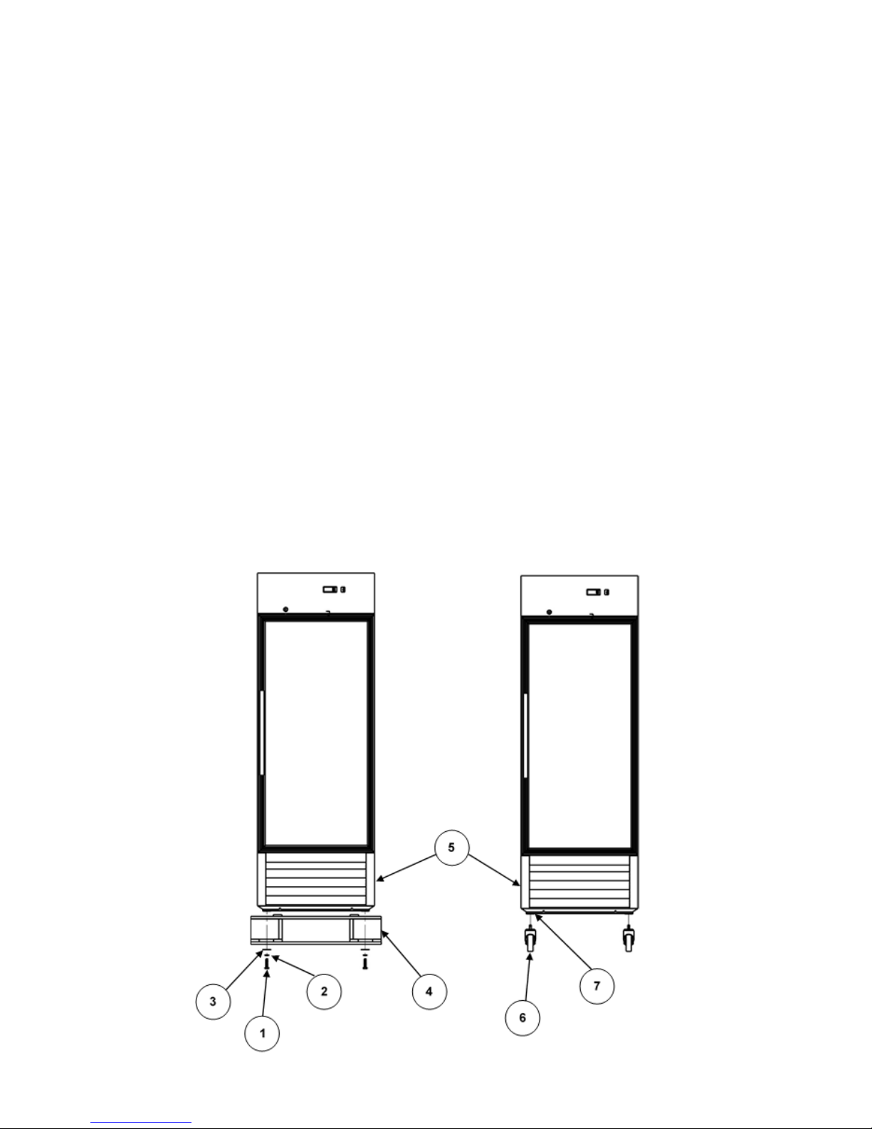
CASTER INSTALLATION
NOTE: There are 4 casters to install. Install the 2 with brakes on front of unit and install the 2 without brakes on rear
of unit.
1.
Remove 4 screws (1), lock washers (2) and flat washers (3). Remove skid (4) from bottom of unit (5).
2.
Screw in the 4 provided stem casters (6) into the base (7) of the unit (5) where the skid mounting screws were
removed.
Page 6 of 58
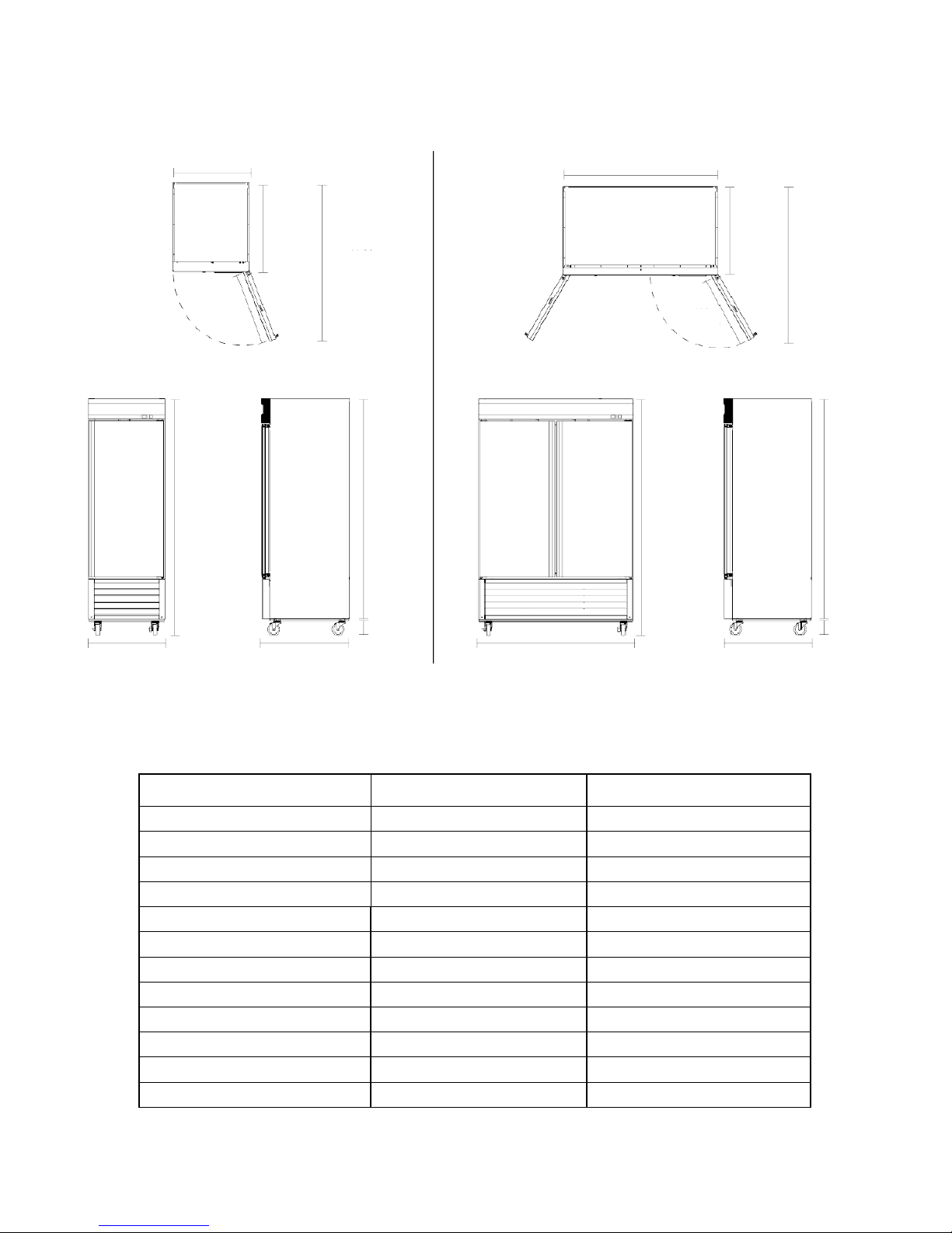
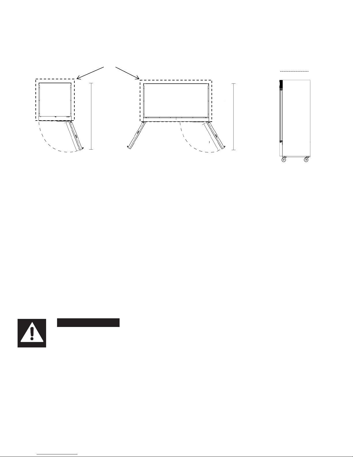
DIMENSIONS
69K-774
69K-765
27 in
686 mm
83.5 in
2121 mm
27 in
686 mm
33.3 in
846 mm
60.5 in
1537 mm
Max Door Swing
Clearance
78.5 in
1994 mm
54.1 in
1374 mm
83.5 in
2121 mm
27 in
686 mm
33.3 in
846 mm
60.5 in
1537 mm
Max Door Swing
Clearance
78.5 in
1994 mm
5 in
127 mm
27 in
686 mm
33.3 in
846 mm
54.1 in
1374 mm
33.3 in
845.8 mm
The overall height of the unit may be reduced by over 2” with an optional shorter caster set of 4 heavy duty casters (2 come with
brakes).
TECHNICAL INFORMATION
Model 69K-765 69K-774
In: Overall Dimension W*D*H 27 x 33.3 x 83.5 54.1 x 33.3 x 83.5
mm: Overall Dimension W*D*H 686 x 846 x 2121 1374 x 846 x 2121
Nominal Capacity 19.3 Cu Ft / 547 L 42.9 Cu Ft / 1215 L
Unit Weight 280 lbs / 127 kg 470 lbs / 213 kg
Hinged Doors 1 2
Shelves 3 6
Electrical Service 110V/60Hz/1Ph 110V/60Hz/1Ph
Wattage 320 W 520 W
Average Amp Draw 1.5 3.7
Refrigerant R-404A R-404A
Provided 6’ NEMA Cord Set 5-15 5-15
Factory T emperature Setting 5°F (-15°C) 5°F (-15°C)
5 in
127 mm
Page 7 of 58
RECEIVING AND INSPECTING THE EQUIPMENT
69K-765
69K-774
FREEZER
DOOR (RIGHT)
THERMOSTAT
FREEZER
THERMOSTAT
FREEZER
Even though most equipment is shipped crated, care should be taken during unloading so the equipment is not damaged
while being moved into the building.
1. Visually inspect the exterior of the package and skid or container. Any damage should be noted and reported to the
delivering carrier immediately.
2. If damaged, open and inspect the contents with the carrier.
3. In the event that the exterior is not damaged, yet upon opening, there is concealed damage to the equipment, notify the
carrier. Notification should be made verbally as well as in written form.
4. Request an inspection by the shipping company of the damaged equipment. This should be done within 10 days from
receipt of the equipment.
5. Be certain to check the compressor compartment housing and visually inspect the refrigeration package. Be sure lines are
secure and base is still intact.
6. Freight carriers can supply the necessary damage forms upon request.
7. Retain all crating material until an inspection has been made or waived.
INTRODUCTION
This user’s manual is intended for installing, using and servicing your Kratos Appliance. It is recommended that this
manual be kept in an accessible place. Every Kratos machine is designed and manufactured according to the highest
standards of safety and performance. It meets or exceeds the safety standard of UL 471 and sanitation standard NSF
7.
Kratos assumes no liability or responsibility of any kind for products manufactured by Kratos, that have been altered in
any way, including the use of any parts and/or other components not specifically approved by Kratos reserves the right
to make design changes and/or improvements at any time. Specifications and designs are subject to change without
notice.
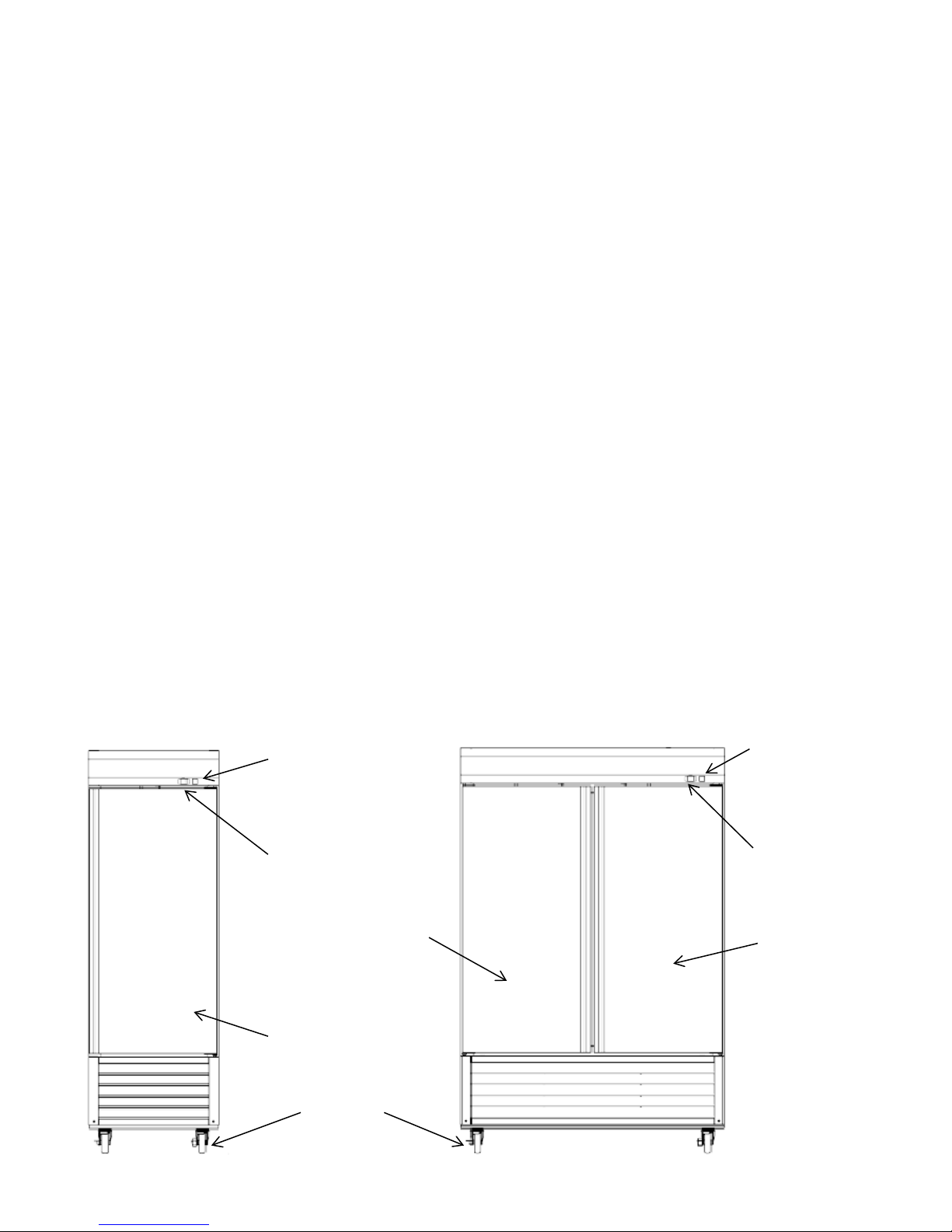
COMPONENT INFORMATION
ON/OFF SWITCH
CONTROL PANEL
ON/OFF SWITCH
CONTROL PANEL
DOOR
CASTERS
(refer to caster
installation for
DOOR (LEFT)
mounting)
Page 8 of 58

FREEZER INSTALLATION
WARNING
Excessive Weight Hazard
Use two or more persons to move and install freezer.
Failure to do so may result in back or other injury.
Remove Packaging Materials
IMPORTANT:
Do not remove any permanent instruction labels or the data label on your freezer.
• Remove tape and glue from your freezer before using.
• To remove any remaining tape or glue, rub the area briskly with your thumb. Tape or glue residue can also be
easily removed by rubbing a small amount of liquid dish soap over the adhesive with your fingers. Wipe with
warm water and dry with a soft cloth.
• Do not use sharp instruments, rubbing alcohol, flammable fluids, or abrasive cleaners to remove tape or glue.
These products can damage the surface of your freezer.
NOTICE:
LOSS OR SPOILAGE OF PRODUCTS IN YOUR FREEZER IS NOT COVERED BY WARRANTY. IN ADDITION TO
FOLLOWING RECOMMENDED INSTALLATION PROCEDURES. PLEASE RUN THE FREEZER 24 HOURS PRIOR TO
USAGE.
Location Requirements
• Freezers represented in this manual are intended for indoor use only.
• Be sure the location chosen has a floor strong enough to support the total weight of the cabinet and contents as a
fully loaded unit can weigh as much as 1500 pounds.
• Reinforce the floor as necessary to provide for maximum loading.
• For the most efficient refrigeration, be sure to provide good air circulation inside and out.
Inside cabinet:
Do not pack the units so full that air cannot circulate. The refrigerated air is discharged at the top rear of the unit. It is
important to allow for pr oper air flow from the top rear to the bottom of the unit. Obstructions to this air flow can cause
evaporator coil freeze ups and loss of temperature or overflow of water from the evaporator drain pan. The shelves have
a rear turn up on them to prevent this. However, bags and other items c an still be located to the far rear of the cabinet. Air
is brought into the evaporator coil with fans mounted to the front of the coil.
Outside cabinet:
Be sure that the unit has access to ample air. Avoid hot corners and locations near stoves and ovens.
It is recommended that the unit be installed no closer t han 2" (51mm) from any wall, a max door swing clearance of 60.5
in. (1537mm) and with at least a 12" (305mm) of clear space above the unit.
Page 9 of 58
FREEZER INSTALLATION (cont.)
Installation Clearance
69K-765
27 in
686 mm
2”
51mm
60.5 in
1537 mm
Max Door Swing
Clearance
69K-774
27 in
686 mm
60.5 in
1537 mm
Max Door Swing
Clearance
12” (305mm) clear space
Leveling
Ensure the floor where the unit is to be located is level.
Stabilizing
All models are supplied with casters for your convenience (refer to caster installation for mounting). It is very important,
however, that the cabinet be installed in a stable condition with the front wheels locked while in use. Should it become
necessary to lay the unit on its side or back for any reason, allow at least 24 hours before start-up to allow compressor oil
to flow back into place. Failure to meet this requirement can cause compressor failure and unit damage.
NOTICE:
Unit repairs will not be subject to standard unit warr anties if due to improper installation procedures.
Electrical Connection
Refer to the amperage data on the Technical Information table, the serial tag, your local code or the National Electrical
Code to be sure that unit is connected to the proper power source.
DANGER
The unit must be turned OFF and disconnected from the power source whenever
performing service, maintenance functions or cleaning the refrigerated area. Failure to
comply may result in Death or Severe Personnel Injury.
Page 10 of 58
OPERATION (Units Made Prior to July 2018)
Press and release
Press and release
• Scroll through menu items
• Scroll through menu items
• Increases values
• Decreases values
Press for at least 5 seconds
Press for at least 5 seconds
• Activates the Manual Defrost function
• Configurable function by user
Press and release
Press and release
• Returns to the previous menu level
• Displays alarms (if active)
• Confirms parameter value
• Opens Machine Status menu
Press for at least 5 seconds
• Confirm commands
• Activates the Standby function (OFF)
Press for at least 5 seconds
(when outside the menus)
• Opens Programming menu
Refrigerated cycle
Freezers: The evaporator fans will run at any time when the evaporator coil temperature is below 54° F (12°C). Fans will
also keep running when door is open but cycle off during a defrost period. The door switch will activate the lights when
opened.
1.
Every 8 hours, the unit will turn off and electric heater will turn on to defrost. The controller now displays the defrost
symbol. When the coil temperature reaches 41°F (5°C) or after 30 minutes of defrost, the unit will turn on again.
2.
Anti-condensation heaters on door frames work in conjunction with the compressor.
3.
Recommended holding temperature range: -10° to 10°F (-23° to 12°C).
4.
Comes factory set to 5°F (-15°C).
Power Switch:
The power switch is located on the front of the bottom panel. When the unit is on, the switch will glow green.
SOLID-STATE THERMOSTAT DESCRIPTIONS (Units Made Prior to July 2018)
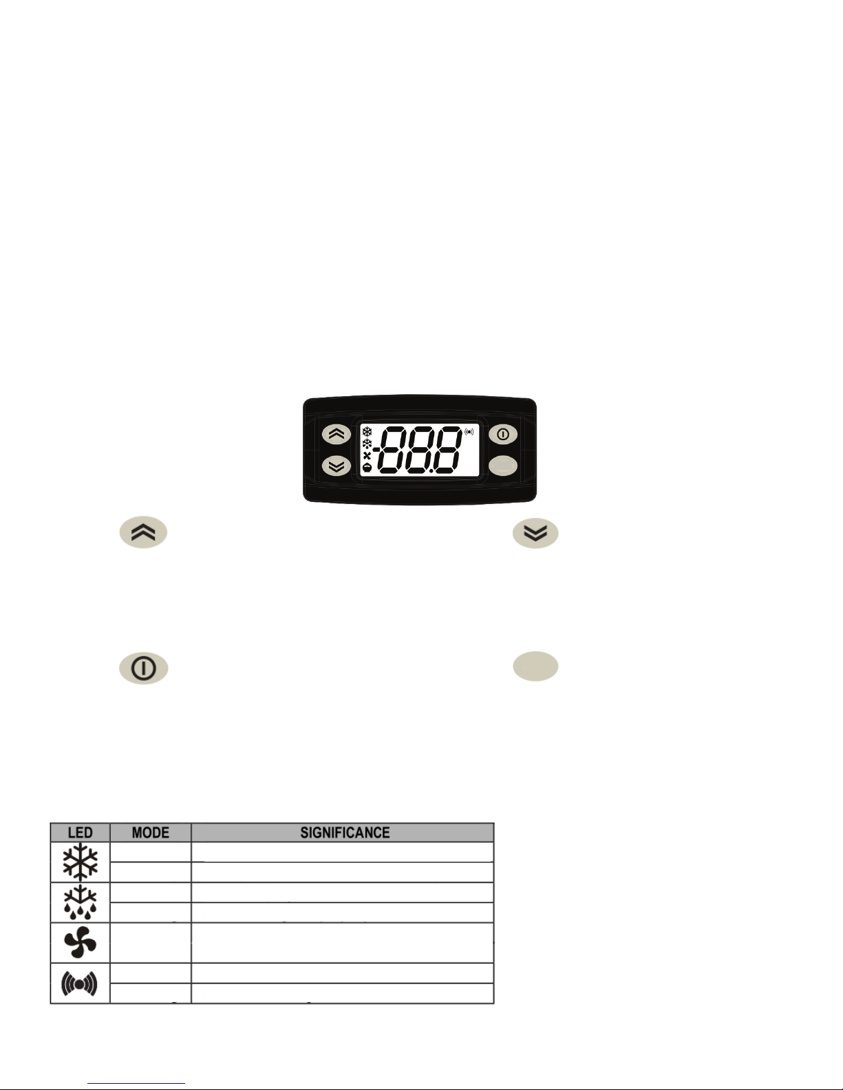
1. FRONT PANEL COMMANDS
ºF
AUX
SET
ºC
1.1 Function of LEDS
On
Flashing
On
Flashing
On
On
Flashing
set
Compressor enabled
a delay , a protection or a locked start-up
Defrost in progress
manual or Digital Input (D.I.) activation
Fans output enabled
alarm active
alarm acknowledged
Page 11 of 58
OPERATION (Units Made Prior to July 2018) (cont.)
Label
Cause
Effects
• Display label E1
OFt
• Display label E2
• The evaporator fans will work in Duty Cycle mode
value read by Pb1>HAL after time of
ALARMs’)
value read by Pb1<LAL after time of
ALARMs’)
• Recording of label EA in folder AL
Regulation locked if EAL = y
digital input activation
(for longer than tdO)
• Recording of label Opd in folder AL
• Controller locked
end of defrost cycle due to timeout
Pb2.
2. MAIN FUNCTIONS
2.1 HOW TO SEE THE SET POINT
1. Push and immediately release the SET key: the 'SET' label appears;
2. To display the Set point value press the SET key;
3. Wait about 15 seconds to return to normal visualization.
2.2 HOW TO CHANGE THE SETPOINT
1. Push and immediately release the SET key: the 'SET' label appears;
2. To display the Set point value press the SET key;
3. To change the Set value push the or arrows.
4. Press SET key to confirm the modification.
2.3 HOW TO START A MANUAL DEFFROST
Push the key for more than 5 seconds and a manual defrost will start. If the defrost conditions:
• parameter OdO ≠ 0
• probe Pb2 temperature is higher than the defrost end temperature
are not satisfied, the display will flash 3 times, to indicate that the operation will not be carried out.
2.4 TO LOCK THE KEYBOARD
It is possible to disable the keypad on this device. The keypad can be locked by programming the ‘LOC’ parameter.
With the keypad locked you can still access the ‘Machine Status’ menu by pressing SET key to display the Set point,
but you cannot edit them.
2.5 TO UNLOCK THE KEYBOARD
To disable the keypad lock repeat the locking proc edur e.
SET
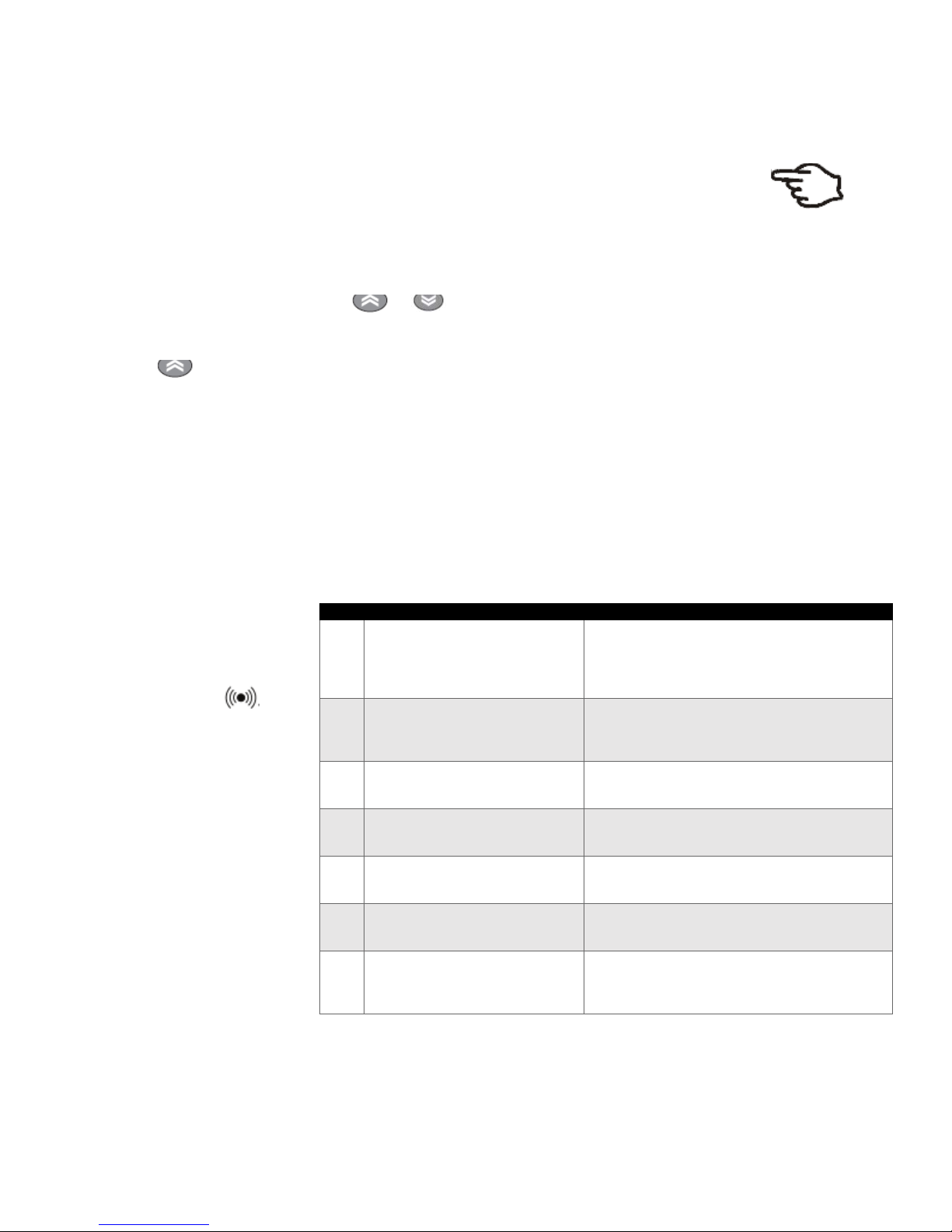
3. ALARM SIGNALLING
Alarms are always indicated
by the buzzer (if present)
and the alarm icon .
To switch off the buzzer,
press and release any key;
the corresponding icon will
continue to flash.
• measured values are outside
E1
operating range
• Probe faulty/short-circuited/open
• measured values are outside
E2
operating range
• Probe faulty/short-circuited/open
AH1
tAO. (see ‘MAX/MIN TEMPERATURE
AL1
tAO. (see ‘MAX/MIN TEMPERATURE
digital input activation
EA
(H11 = ± 5)
OPd
(H11 = ± 4)
rather than due to defrost end
Ad2
temperature being recorded by probe
• Alarm icon permanently on
• Disable max/min alarm controller
• Compressor operation based on parameters Ont and
• Alarm icon permanently on
• The Defrost cycle will end due to Timeout (dEt)
• Recording of label AH1 in folder AL
• No effect on regulation
• Recording of label AL1 in folder AL
• No effect on regulation
• Alarm icon permanently on
•
• Alarm icon permanently on
• Recording of label Ad2 in folder AL
• Alarm icon permanently on
Page 12 of 58
OPERATION (Units Made After July 2018)
Refrigerated cycle
Freezers: The evaporator fans will run at any time when the evaporator coil temperature is below 54° F (12°C). Fans will also keep
running when door is open but cycle off during a defrost period. The door switch will activate the lights when opened.
5.
Every 8 hours, the unit will turn off a nd e le c tric heater will turn on to defrost. The controller now displays the defrost symbol.
When the coil temperature reaches 41°F (5°C) or after 30 minutes of d efrost, the unit will turn on agai n.
6.
Anti-condens ation heate rs on doo r frames work i n conjunction with the compresso r.
7.
Recommended holding temperature range: -10° to 10°F (-23° to 12°C).
8.
Comes factory set to 5°F (-15°C).
Power Switch:
The power switch is located on the front of the bottom panel. When the unit is on, the switch will glow green.
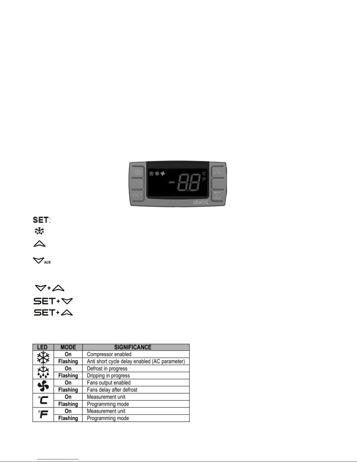
SOLID-STATE THER MOSTAT DESCRIPTIONS (Units Made After July 2018)
1. FRONT PANEL COMMANDS.
To di splay tar get set point; in programming mode it selects a parameter or confirm an operation.
To start a manual defrost.
In programming mode it browses the parameter codes or increases the displayed value.
In programming mode it browses the parameter codes or decreases the displayed value.
S COMBINATION
KEY
To l ock or unlock the keyboard.
To e nter in programming mode.
To r etu rn t o room t em perature di s play.
1.1 Function of LEDS
Page 13 of 58

OPERATION (Units Made After July 2018) (cont.)
2. MAIN FUNCTIONS
2.
1 HOW TO SEE THE SET POINT
1. Push and immediately release the SET key, the set point will be showed;
2. Push and immediately release the SET key or wait about 5s to return to normal
visualization.
2.2 HOW TO CHANGE THE SETPOINT
1. Push the SET key for more than 2 seconds to change the Set point value;
he value of the set point will be displayed and the “°C” or “°F” LED starts blinking;
2. T
3. To change the Set value push the or arrows.
4. To memorize the new set point value push the SET key again or wait 10s.
2.3 HOW TO START A MANUAL DEFFROST
Push the DEF key for more than 2 seconds and a manual defrost will start
2.4 TO LOCK T HE KEYB OAR D
1. Keep pressed for more than 3s the and keys.
2. The “OF” message will be displayed and the keyboard will be locked. If a key is pressed more
than 3s the “OF” message will be displayed.
2.5 TO UNLOCK THE KEYBOARD
Keep pressed together for more than 3s the and keys till the “on”
message will be displayed.
3. ALARM SIGNALLING
3.
1. ALARM RECOVERY
Probe alarms P1” and “P2” start some seconds after the fault in the related probe ; they automatically
stop some seconds after the probe restarts normal operation. Check connections before replacing the
probe. T em perature alarms “HA” and “LA” automatically stop as soon as the temperature returns to normal values.
Alarms “EA” and “CA” (with iF=bL) recover as soon as the digital input is disabled.
Page 14 of 58

CLEANING AND MAINTENANCE
DANGER
The unit must be turned OFF and disconnected from the power source whenever
performing service, maintenance functions or cleaning the refrigerated area. Failure to
comply may result in Death or Severe Personnel Injury.
Exterior and Interior Cleaning of Freezers
Clean using soap a nd war m w ater. If this isn't suf fic ien t, try ammonia and water or a no nab ra sive l iqu id clean er. When cleaning
the exterior, always rub with the "grain" o f the stainl e ss steel t o avoi d mar ring th e fini s h.
• Do not use an abrasive clean er becau se it will scratch the stainle ss steel and plasti c and can damage the breaker strip s
and gaskets.
Cleaning the Condenser Coil
Regular cleaning is recommended every 90 days. In some instances, you may find that there is a large amount of debris and
dust or grease accumulated prior to the 90 day time frame. In these cases the condenser coil should be cleaned every 30
days.
If the buildup on the coil consists of only light dust and debris, the condenser coil can be cleaned with a simple brush. Heavier
dust build-up may require a vacuum or even compressed air to blow through the condenser coil.
If heavy grease is present, there are de-greasing agents available for refrigeration use and specifically for the condenser coils.
The condenser coil may require cleaning with the de-greasing agent and then blown through with compressed air.
Failure to maintain a clean condenser coil can initially cause high temperatures and excessive run times. Continuous
operation with dirty or clogged condenser coils can result in compressor failures. Neglecting the condenser coil cleaning
procedures will void any warranties associated with the compressor or cost to replace the compressor.
• For efficient operation, keep the condenser surface free of dust, dirt, and lint.
• We recommend cleaning the condenser coil at least once per month.
• Clean the condenser with a commercial condenser coil cleaner and a soft brush, available from any commercial
refrigeration equipment retailer, or vacuuming the condenser with a shop vac or use CO2.
CAUTION
Never use a high pressure water wash for this cleaning procedure as water can damage
the electrical components located near or at the condenser coil.
In order to maintain proper refrigeration performance, the condenser fins must be cleaned of dust, dirt and grease
regularly. It is recommended that this be done at least every three months. If conditions are such that the condenser is
totally blocked in three months, the frequency of cleaning should be increased. Clean the condenser with a vacuum
cleaner or stiff brush. If extremely dirty, a commercial-grade condenser cleaner may be required.
Page 15 of 58

CLEANING AND MAINTENANCE (cont.)
Stainless Steel Care and Cleaning
To prevent rust or discoloration on stainless steel several important steps need to be taken. First, we need to understand the
properties of stainless steel. Stainless steel contains 70-80% iron which will rust. It also contains 12-30% chromium which
forms an invisible passive film over the steels surface which acts as a shield against corrosion. As long as the protective layer
is intact, the metal is still stainless. If the film is broken or contaminated, outside elements can begin to breakdown the steel
and begin to form rust or discoloration.
CAUTION
Proper cleaning of stainless steel requires soft cloths or plastic scouring pads, never use
steel pads, wire brushes or scrapers!
Cleaning solutions need to be alkaline based or non-chlori de bas ed . Any cleaner containing chlorides will damage the
protective film of the stainless steel. If cleaners containing chlorides are used, be sure to rinse and dry thoroughly.
Routine cleaning of stainless steel can be done with soap and water. Extreme stains or grease should be cleaned with a
non-abrasive cleaner and plastic scrub pad. It is always good to rub with the grain of the steel. There are also stainless
steel cleaners available which can restore and preserve the finish of the steel’s protective layer.
Early signs of stainless steel breakdown can consist of small pits and cracks. If this has begun, clean thoroughly and start
to apply stainless steel cleaners in attempt to restore the passivity of the steel.
CAUTION
Never use an acid based cleaning solution!Many food products have an acidic content which
can deteriorate the finish. Be sure to clean the stainless steel surfaces of ALL food products.
Gasket Maintenance
Gaskets require regular cleaning to prevent mold and mildew build up and also to keep the elasticity of the gasket.
Gasket cleaning can be done with the use of warm soapy water. Avoid full strength cleaning products on gaskets. Do not
use sharp tools or knives to scrape or clean the gasket.
Gaskets can easily be replaced and don’t require the use of tools or authorized service technicians. The gaskets are
"Dart" style and can be pulled out of the grove in the door and replaced by pressing the new one back into place.
Doors/Hinges
If the door is beginning to sag, tighten the screws that mount the hinge brackets to the frame of the unit. If the doors are
loose or sagging, this can cause the hinge to pull out of the frame which may damage both doors and door hinges.
Drain Maintenance
Each unit has a drain located inside the unit which removes the condensation from the evaporator coil and evaporates it into
an external condensate evaporator pan. The drain can become loose or disconnected. If you notice excessive water
accumulation on the inside of the unit, be sure the drain tube is connected from the evaporator housing to the condensate
evaporator drain pan.
If water starts to collect underneath the unit, check the condensate evaporator drain tube to be sure it is still located inside
the drain pan.
If your floor is not level, this can also cause drain problems. Be sure all drain lines are free of obstructions because this may
cause water to back up and overflow the drain pans.
Page 16 of 58
TROUBLESHOOTING GUIDE
Set thermostat to lower
temperature.
clearance from the fan
closed.
on the Cabinet and/or Floor
gasket as necessary
BEFORE CALLING FOR SERVICE
If the unit appears to be malfunctioning, read through the OPERATION section of this manual first. If the problem
persists, see Troubleshooting below. The problem may be something very simple that can be solved without a service
call.
TROUBLESHOOTING
Fault Probable Cause Action
Replace fuse or reset circ uit
Fuse blown or circuit breaker
tripped
Compressor is Not Runn i ng
Power cord unplugged Plug in power cord
breaker. If replaceme nt of fuse or
reset of circuit breaker do esn’t
correct the problem contact a
qualified service technician.
Cabinet Temperature is t oo
Warm
Interior Light is Not Working
Thermostat set too high
Thermostat is set too high
Airflow is blocked
Low refrigerant levels
Door is slightly ajar
Poor switch connection
Bulb is not connected
Bulb has burned out
temperature
Set thermostat to lower
Re-arrange products t o allow for
proper air flow. Make sure there
is at least four inches of
Contact a qualified service
technician to check refr ige r ant
levels
Make sure door is completely
Turn off light switch and tu r n it
back on.
Make sure the bulb is correctly
inserted in the socket.
Replace the bulb. If replacem ent
of bulb doesn’t correct the
problem contact a qualified
service technician.
Condensation is Collecting
Gasket is not sealing proper ly
Page 17 of 58
Clean, repair, or replace t he
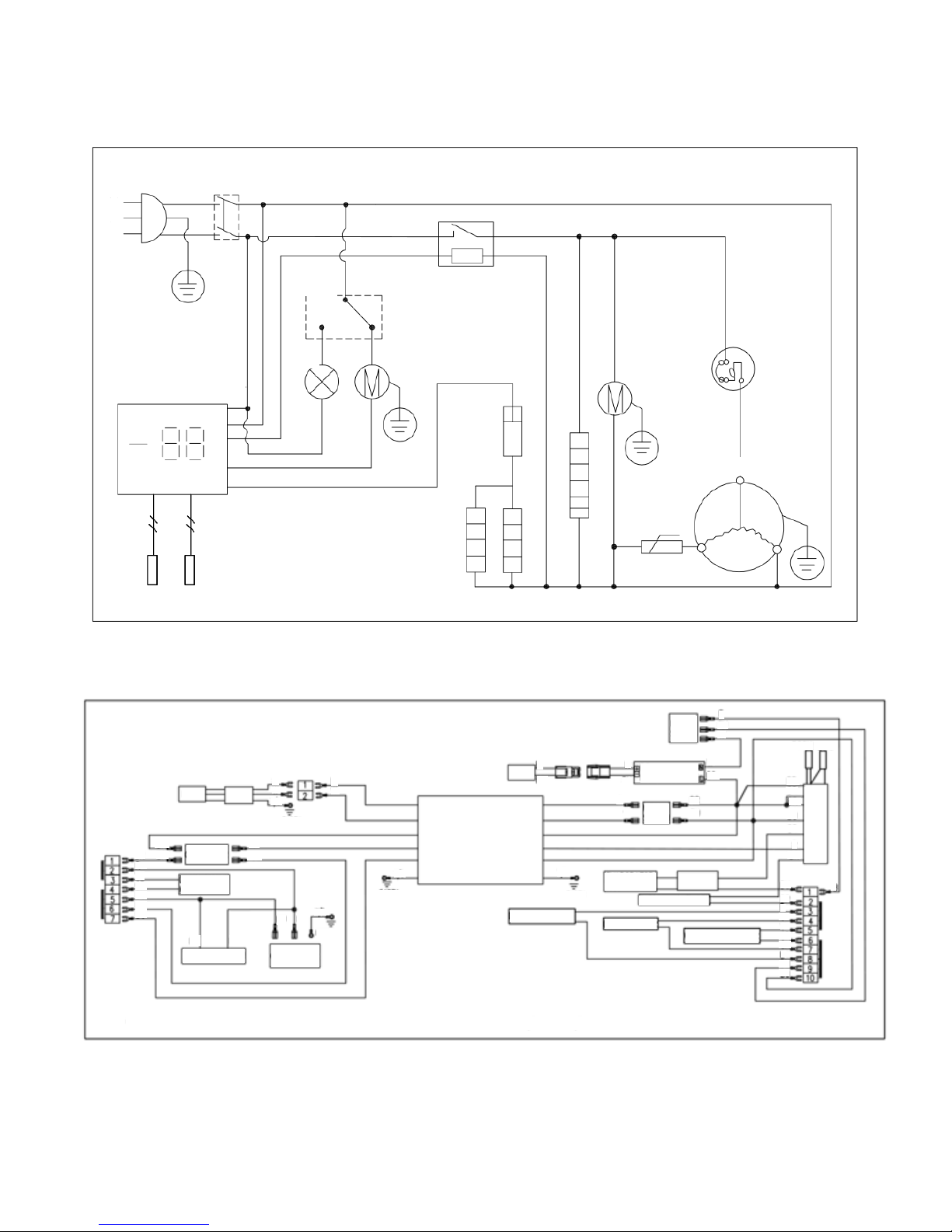
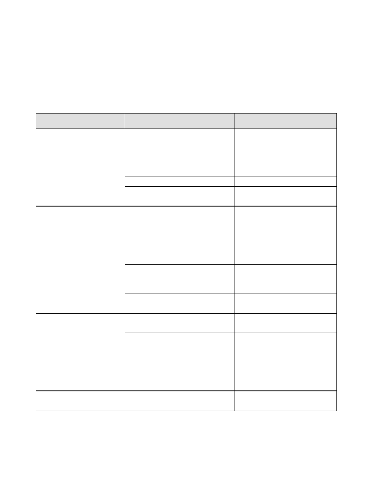
WIRING DIAGRAMS
SWITCH
N
L
MODEL:69K-765
POWER
PLUG
THERMOSTAT DISPLAY
ROOM
BR
GR
BU
BU
BU
R
Y
BR
BR
EVAP
PLUG
CONTACTOR
DOOR FRAME
HEATER
BU BR
CONDENSER FAN
R
BU
DOOR
SWITCH
LAMP
B
W
Y/G
EARTH
R
BU
COMPRESSOR
Y/G
EARTH
CONTACTOR
CIRCULATION
FAN MOTOR
CONDENSER
FAN MOTOR
OVERLOAD
PROTECTOR
THERMAL
CUT-OFF
DOOR FRAME HEATER
COMPRESSOR
t ºC
DEFROST HEA TER
PIPE HEA TER
PTC ST ARTER
B
DOOR
SWITCH
R
B
W
Y/G
EARTH
LAMP
BU
DEFROST HEATER
Y/G
EARTH
R
BU
B
W
EVAPORATOR
FAN
DRAIN HEATER
DC POWER
SUPPLY
MAIN
SWITCH
THERMAL CUT-OFF
BU
W
W
BR
BR
BU
WATER BOX HEA TER
EVAP
ROOM
BR
BR
BR
BU
BR
R
THERMOSTAT DISPLAY
BR
BU
BR
B
Y
Y
GR
GR
B
BU
BU
B
* RED-R BLACK-B BLUE-BU BROWN-BR WHITE-W YELLOW-Y GRAY-GR YELLOW/GR EEN-Y/G
Page 18 of 58
 Loading...