

Page 1
www.kraenzle.com
GB
Original-Operating manual
High-pressure cleaners
W 11/135
W 13/230
W 15/200
W 19/160
Read and conform safety instructions before use!
Keep instructions in a safe place for later use and
pass them on to any future user.
Page 2

2
Dear Customer
We would like to congratulate you on your new high pressure cleaner and to thank
you for the purchase.
To ease your introduction to the use of the cleaner, we have provided the following
pages of explanations, tips and hints.
The equipment will assist you professionally in all cleaning tasks, e.g.:
Description
Operating pressure steplessly adjustable
Permiss. overpressure
Water output *
Hot water input
High pressure hose
Electrical ratings
Connected load Input
Output
Weight
Dimensions
Sound lever accord.
to DIN 45 635 (rel. to working place)
with dirtkiller
Recoil at lance
Torque
Vibrations at lance
Order n°:
10 - 135 bar
150 bar
at 1400 rpm
11 l/min
max. 60 °C
10 m
230 V ; 50 Hz ;
14,0 A
P1: 3,3 kW
P2: 2,4 kW
76 kg
710 x 740 x 370
89 dB
84 dB
approx. 25 Nm
26 Nm
2,4 m/s²
41 312
Kränzle
W 11 / 135
Technical
specications
Kränzle
W 19 / 160
Kränzle
W 15 / 200
Kränzle
W 13 / 230
10 - 160 bar
180 bar
at 1400 rpm
19 l/min
max. 60 °C
10 m
400 V ; 50 Hz ;
12 ,5A
P1: 7,5 kW
P2: 5,5 kW
90 kg
710 x 740 x 370
89 dB
93 dB
approx. 22 Nm
24,3 Nm
3,2 m/s²
41 310
10 - 200 bar
220 bar
at 1400 rpm
15 l/min
max. 60 °C
10 m
400 V ; 50 Hz ;
12,5 A
P1: 7,5 kW
P2: 5,5 kW
90 kg
710 x 740 x 370
89 dB
93 dB
approx. 25 Nm
28,8 Nm
3,2 m/s²
41 309
10 - 230 bar
250 bar
at 1400 rpm
13 l/min
max. 60 °C
10 m
400 V ; 50 Hz ;
12,5 A
P1: 7,5 kW
P2: 5,5 kW
90 kg
710 x 740 x 370
89 dB
93 dB
approx. 27 Nm
28,8 Nm
3,2 m/s²
41 308
(Assumed length of lance: 0.9 m)
Permissible tolerance for gures ±5% in accordance with VDMA, uniform sheet 24411
* Min. water quantity to be supplied to the high pressure cleaner!
- Vehicles of all types
- Barrels and containers
- Machines etc.
- Removing old
paint
Page 3
3
Preparation for use
Stationary cold water high pressure cleaner
The stationary wall-mounted systems are supplied with a stainless steel housing
and equipped with an AQ pump (W11/135 with APG pump) and 10m steel fabric
heavy duty hose.
Pressure fully adjustable, automatic total-stop feature.
After the gun is closed, the device continues to run for a time and then cuts out. It
restarts when the gun is opened. Incorrect operation by unauthorised persons is
therefore not possible. The factory setting is 30 seconds. The device is connected
to a water supply with advance pressure. Temperatures of up to 60 °C are possible.
Features
Stainless steel housing,
10 m heavy duty hose with gun,
lance 800 mm
control nozzle and HP nozzle.
Preparation for use
Connect to suitable water supply, open the water tap.
Switch on high-pressure cleaner. The pump is running and the pressure is built
up. If the gun remains closed, the cleaner continues to run for another 30 seconds
and then switches automatically into standby.
As soon as you presser the trigger of the gun the high-pressure pump starts.
After closing the gun, it continues to run for approx. 30 seconds, and then
switches back to standby mode.
The device continues to run once the trigger is pressed during the 30 seconds.
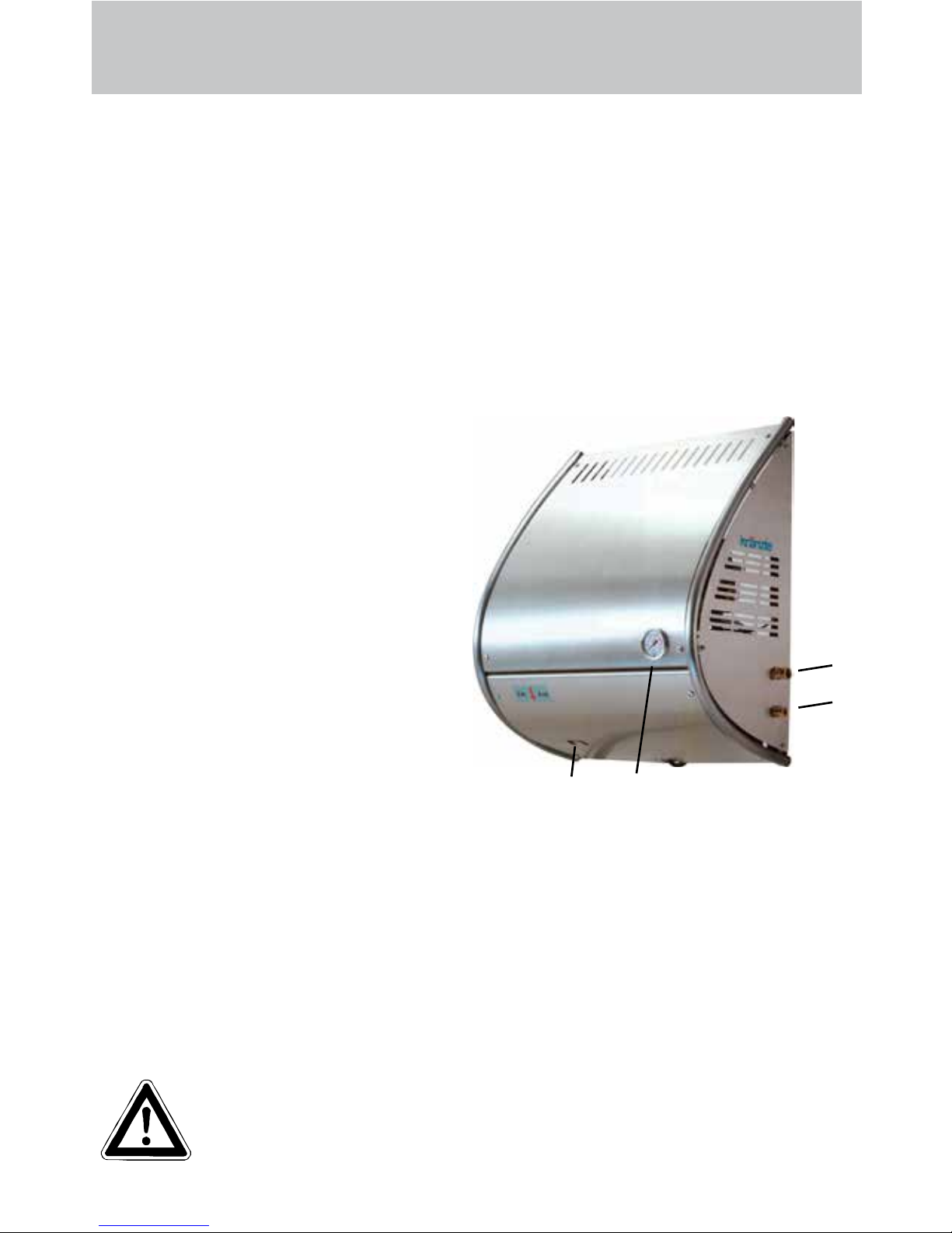
1 Water inlet connection
2 High-pressure outlet
3 Press.gaugewithglycerinlling
4 On-/ Off switch
Function
2
1
34
If you use the HP cleaner for the rst time or if you have not worked
with your cleaner for a longer period of time, the machine has to be
deaerated by opening and closing the gun various times.
Page 4

4
Description
Water supply system
The water is fed under pressure (2 - 8 bar) to the HP pump. Then the water is fed
under pressure from the HP pump to the safety spray lance. The high pressure jet
is formed by the nozzle at the end of the lance.
The machine can only be operated when the safety trigger is squeezed.
When the lever is squeezed, the spray gun opens. The liquid is then pumped to
the nozzle.
When the trigger is released, the spray gun closes and any further spraying of
liquid from the lance is stopped and the manometer must show 0 bar.
The increase in pressure when the spray gun is closed causes the unloader
valve-safety valve to open. The pump remains switched on and continues to pump
liquid through the pump at reduced pressure. When the spray gun is opened, the
unloader valve - safety valve closes and the pump ressumes pressure spraying
from the lance.
The spray gun is a safety device. Repairs should only be performed by qualied persons. Should replacement parts be required, use only components authorized by the manufacturer.
Lance with spray gun
The unloader valve - safety valve protects the machine from a build up of excess
pressure, and is designed not to permit an excess pressure to be selected for
operation. The limit nut on the handle is sealed with a spray coating.
The operating pressure and spray rate can be steplessly adjusted by turning the
handle.
Replacements, repairs, new adjustments and sealing should only
be performed by qualied persons.
Unloader valve - safety valve
Environmental, refuse disposal and water protection
regulations must be observed !
Page 5

Description
5
High pressure hose and spraying device
The high pressure hose and spraying device supplied with the machine are made
of high grade material. They are also optimized for the machine and marked as
required by the appropriate regulations.
If replacement parts are required, only such parts that are authorized
by the manufacturer and which bear the markings required by the appropriate regulations may be used. The high pressure hose and spraying device must be connected in a pressure-tight manner.
The high pressure hose may not be driven over, pulled excessively
or twisted. Make sure that the hose is not damaged on sharp edges.
Hose lines are wear parts. Guarantee is accepted only for manufacturing errors, not for external damages.
High pressure hose lines and spraying equipment must not be
repaired, but replaced by a new hose or spraying equipment.
Unloader valve - safety valve
The unloader valve - safety valve protects the machine from a build up of excess
pressure, and is designed not to permit an excess pressure to be selected for
operation. The limit nut on the handle is sealed with a spray coating.
The operating pressure and spray rate can be steplessly adjusted by turning the
handle.
Replacements, repairs, new adjustments and sealing should only
be performed by qualied persons.
Take care that all screw connections are pressure-tight. A leakage
of gun, high-pressure hose or hose drum has to be repaired at once.
Leakages lead to an increased wear and to a possible malfunction
of the delayed motor cut-out.
Operator’s task:
Prior to each usage of this liquid spraying device, the operator is obliged to
check if all safety relevant parts are in perfect working condition.
(e.g. safty valves, high-pressure hose, cables and connections,
spraying devices, etc. )
Page 6

6
Description
With delayed motor cut-out
Frequent, work-necessitated switching on and off of motors on
machines of this size puts a heavy load on the power network and
causes increased wear on internal electrical parts. That’s why the
motor on the new KRÄNZLE appliances switches itself off 30 seconds after the
trigger is released, and switches itself back on again when the trigger is pressed.
When running your high pressure cleaner with hot water of 60° C
raised temperatures occur. Do not touch the machine without safety
gloves!
CAUTION !
CAUTION !
Never use liquid containing solvents such as paint thinners, petrol, oil
or similar liquid matter. Pay attention to the instructions of the man-
ufacturers of the cleaning agents. The seals in the machine are not
resistant to solvents. The spray of solvents is inammable, explosive
and poisonous.
Setting up
Location
Neither set up and operate the machine in rooms where there is a risk
of re or explosion nor put it into puddles. Do not use the machine
under water.
Replacements and inspection work should only be performed by quali-
ed persons when the machine is disconnected from the power
supply, i.e. the plug is pulled out from the electrical socket.
Page 7

Description
Electrical connection
The machine is supplied with an electrical power cord with plug.
The mains plug must be tted to a standard grounded socket with a
30mA residual current operated device. The socket must be protected with a 16A delay action fuse on the mains side.
KRÄNZLE W 11-135 = 230 Volt / 50 Hz
KRÄNZLE W 13-230 = 400 Volt / 50 Hz (phase-sequence not signicant)
KRÄNZLE W 15-200 = 400 Volt / 50 Hz (phase-sequence not signicant)
KRÄNZLE W 19-160 = 400 Volt / 50 Hz (phase-sequence not signicant)
When using an extension cable, this must have an earthed lead which is properly connected to the socket. The conductors in the extension cable must have a
minimum cross section of 1.5 mm². Plug connections must be of a spray-proof
design, and may not be located on a wet oor.
(with extension cables of more than 10 m - 2.5 mm2 )
CAUTION !
The use of extension cables which are too long may lead to malfunctions and start
up difculty.
W 13-230;
W 15-200;
W 19-160
400V/50Hz
W 11-135
230V/50Hz
7
Page 8

8
Description
Brief operating instructions:
1. Connect the high pressure hose with spray gun and machine.
2. Connect to suitable water supply.
3. Flush the air from the pump (open and close the spray gun several times).
4. Make the electrical connection - (400 Volt three-phase current).
5. Switch on the machine and commence cleaning.
6. After having completed the work switch off the tap and completely empty
the pump.
(Switch on the motor for approx. 20 sec. without the water hose and gun).
Afterwards you can roll up the high pressure hose.
- Only use clean water ! - Protect from frost !
CAUTION !
Please pay attention to the regulations of your waterworks company.
In accordance with EN 61 770, the machine may not be directly connected to the
public drinking water supply lines.
A brief connection however is permissible according to DVGW (German Associa-
tion for Gas and Water Affairs) if a tube ventilator with check valve (Kränzle OrderNo. 41.016 4) is built into the water supply.
Also indirect connection to the public drinking water supply lines is permissible by
way of free emission in accordance with EN 61 770; e.g. by using a reservoir with
a oat valve.
Direct connection to a non-drinking water supply line is permissible.
Page 9

9
Preparation for use
1. Check oil level.
There are two
possibilities for checking the oil level of the pump:
a) Oil must be visible in the viewing window
b) The oil level must be between the two
markings on the oil dipstick.
To check the oil level, loosen the oil cover screw and take out the oil dip stick. The
oil level must be between the two markings.
2. Connect the high pressure lance
or dirtkiller to the spray gun.
4. The machine must be connected to the water line with cold water or up to
60° C warm water (see page 2).
The hose cross section must be at least 3/4“ = 16 mm (free passage).
Itisrecommendedtoinstallawaterlterpriortothecleaner.
(Kränzle order no.: 13.300 3)
3. Unroll hose without kinks and connect with
handgun and pump. Max. extension 20m-HP
hose or 2 x 10m with hose connections.
Page 10

To shut down the pump:
10
1. Switch off the machine. Switch to „0“ position.
2. Cut off the water supply.
3.Openthespraygunbrieyuntilthepressureisreleased.
4. Apply the safety catch on the spray gun.
5. Remove the water hose and spray gun.
6. Pull the plug from the socket.
7. Winter: store the pump in rooms above 0°C.
8.Cleanthewaterlter.
To shut down the pump:
Frost protection
Normally after operation, there is still some water in the device. Thus, you must take
special measures to protect the device from frost.
- Completely drain the device
For this purpose, separate the device from the water supply. Then, turn on the
main switch and open the gun. Now, the pump presses the remaining water out of
the water tank and the pump. However, do not allow the device to operate without
water for longer than one minute.
- Fill the device with antifreeze agent
If the device is not operated for longer periods, especially over the winter, you
should pump an antifreeze agent through the device. For this purpose, ll the anti-
freeze agent into the water box and turn on the device. Wait with opened gun,
until the agent spurts out of the nozzle.
However, the best way to protect the device from frost is
to store it at a frost-free location.
Page 11
Care and Maintenance
Care and Maintenance
Care and maintenance is required to keep the machine in good working order, and
to allow you to enjoy the machine for as long as possible.
IMPORTANT!!!
Always remove the plug before working on the machine!
Only use original Kränzle spare parts
What to do!
- Weekly, or after approx. 40 hours of operation
Check the oil level of the high pressure pump.
Loosen the red oil stopper on the high pressure pump and pull out the oil
dipstick.
If the oil level is too low, add oil until the oil level is between the two markings
on the oil dipstick.
Change the oil if it has a grey or whitish appearance. The oil should be disposed of responsibly.
11
Changing the oil
To do this, take the oil drainage hose (1) connected to the oil drain screw, from the
inside of the machine and open the red oil ller cap on the top side of the black oil
reservoir. Open the cap at the end of the hose. Drain off the oil into an oil pan and
dispose of it responsibly. Close the end of the hose.
Rell with oil, es described above.
Oil leakage
If oil leaks out, contact the nearest customer service (dealer) immediately. (Environmental damages, transmission damages, loss of guarantee.)
Type of oil:
W19/160 Formula RS of Castrol - Quantity: 1.0 l
W15/200
W13/230
W11/135 Motor oil: 15/W40 - Quantity: 0.3 l
Page 12

12
Care and Maintenance
Rules, directives, inspections
Inspections performed by Kränzle
- measurement of earth line resistance
- measurement of voltage and current
- inspection of tension consistency with +/- 1530 V
- visual and functional check as per the inspection sheet provided
Guidelines for liquid sprayers
The machine conforms with the „Guidelines for liquid sprayers“. These
guidelines are issued by the organisation of trade associations and may be
obtained from Carl Heymann-Verlag KG, Luxemburger Str. 49, 50939 Köln.
These guidelines specify that this machine is to be inspected by qualied
personnel whenever necessary, but no less than once every 12 months.
These inspections must be recorded in the inspection log at the end of this
manual.
Duties of owner
The owner is to ensure that all safety-relevant components are in a serviceable
condition before the sprayer is used. (e.g., safety valves*, hoses and electric
cables, spray equipment etc).
* The pressure gauge must show 0 bar once the gun is closed.
Page 13

Safety Information
13
Safety Information
Important !!!
The machine must be disconnected from the power supply when ser-
vicing work is being carried out. The master switch should be in position
„0“ and the plug out of the socket.
Do not use the cleaner if electrical connections or other safety-relevant
parts (e.g. overpressure valve, high pressure hose, spraying equipment
etc.) are damaged.
The machine may only be used by persons who have received the necessary training.
Never operate the machine without supervision.
The water spray can be dangerous. It should never be directed at people, animals,
electrical apparatus or the machine itself.
Never direct the spray at power sockets.
Parts of the machine interior and parts of the gun and lance become hot when hot water
is used. Leave the cover of the machine closed when using the machine and do not
touch the metallic parts of the gun and lance.
Children must not use high pressure cleaning equipment.
Do not damage the cable or repair it incorrectly.
Do not pull the high pressure hose if there are kinks or loops in it. Make sure that the hose
is not damaged on sharp edges.
Persons operating the machine should wear the necessary protective clothing, i.e., wa-
terproof clothing, rubber boots, safety goggles, headwear etc. It is prohibited to use the
machine in close vicinity to people lacking suitable protective clothing.
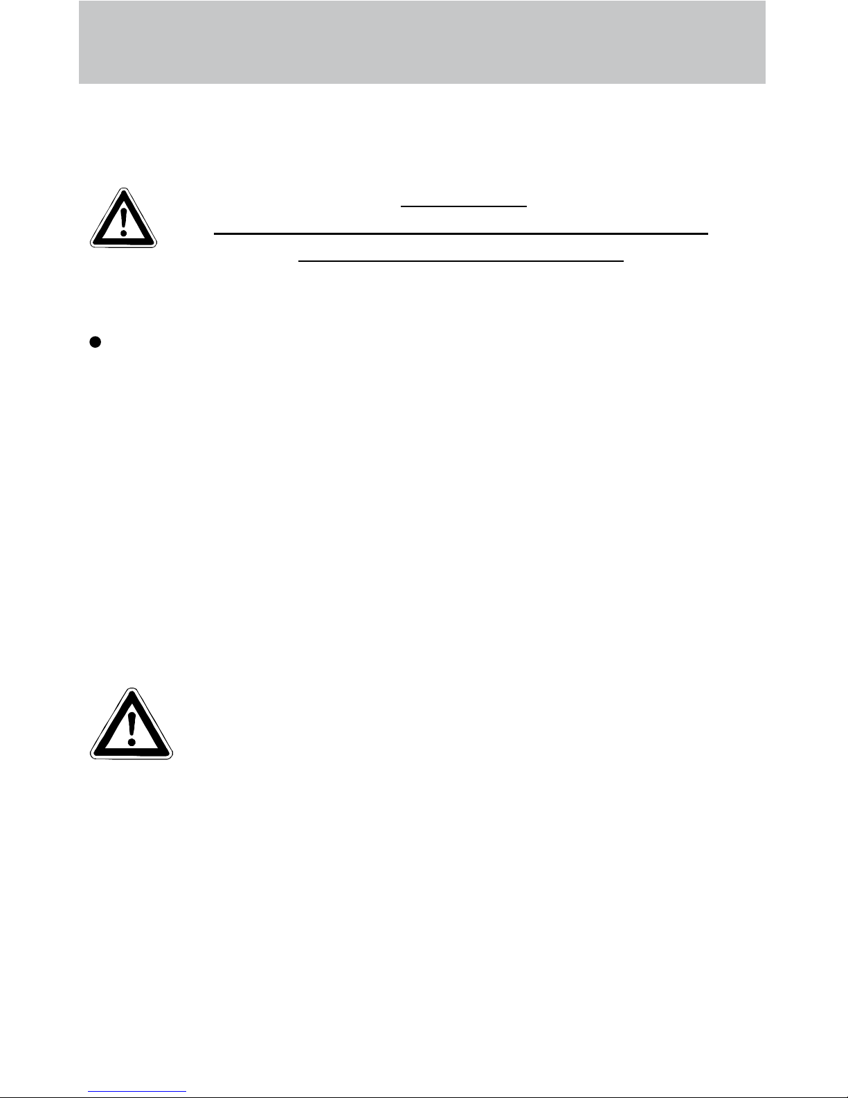
The high pressure spray can generate a high level of noise. If noise exceeds the maximum
allowed levels, users and others in the vicinity must wear suitable ear protection.
The high pressure spray causes recoil and additional twisting movement if the gun is angled.
The gun must therefore be held rmly with both hands. (see page 2)
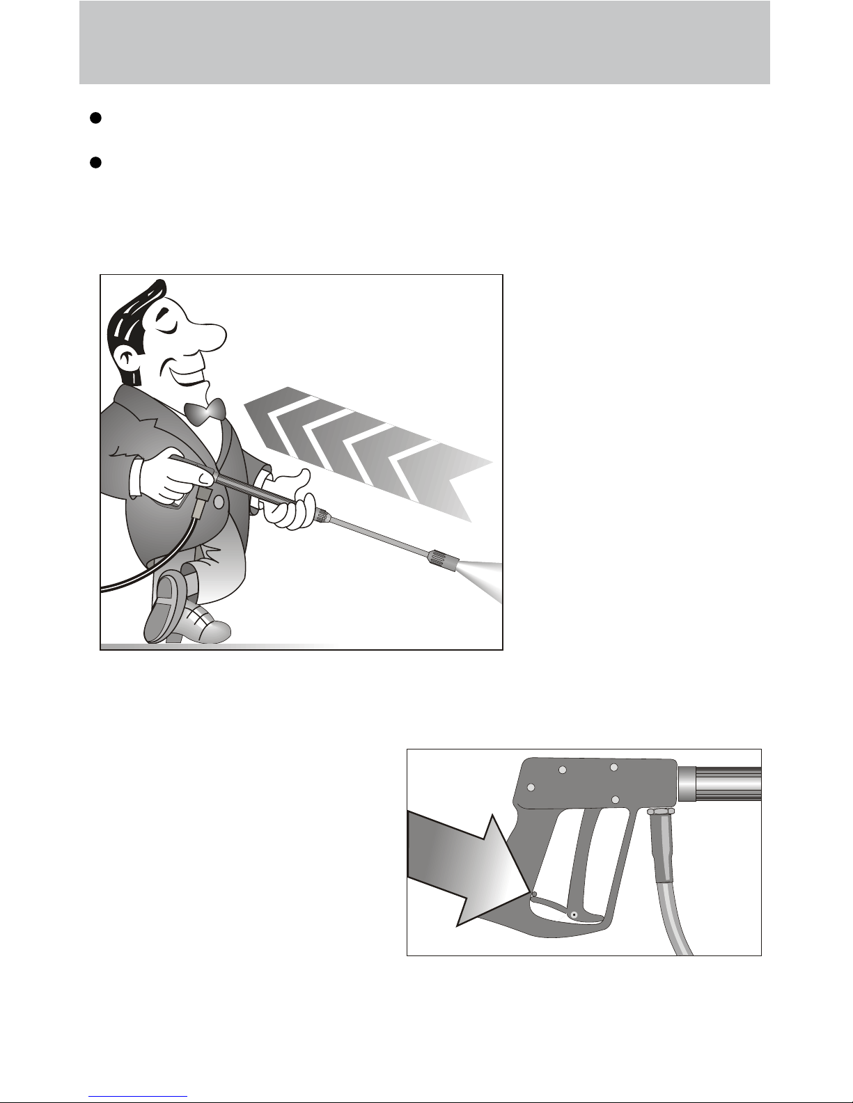
Do not clamp down the trigger of the gun. Apply the safety catch after use, in order to
prevent accidental spraying.
Do not spray against matter containing asbestos or other hazardous substances.
Never spray liquids containing solvents, such as paint thinner, petrol, oil, or anything simi-
lar. Notethespecicationsoftheadditivemakers! The seals in the machine are not
resistant to solvents. The spray vapour of solvents is highly inammable, explosive and
poisonous.
Page 14
14
Safety Information
As to the recoil see notice on page 2!
Apply the safety catch on the
spray gun after each use, in
order to prevent unintentional
spraying!
The machine may not be set up and used in rooms where there is a danger of re or ex-
plosion. The machine may not be used under water.
Never direct the high-pressure jet at yourself or other persons just to clean clothing or
shoes.
Page 15

15
This is prohibited!
Never direct the water jet at the machine
itself!
Never allow children
to use the high pressure cleaner!
Never direct the water
jet at a power socket!
Page 16

16
This is prohibited!
Never direct the water
jet at people or animals!
Do not damage the
power cable or repair
it incorrectly!
Never pull the high
pressure hose if it has
formed kinks or “nooses”!
Never pull the hose
over sharp edges!
Page 17

17
Small repairs - Do it yourself!
Stopping leaks from hose or gun
After closing the gun the manometer shows full pressure!
The pressure regulator switches on and off contunuously!
If the
manometer
shows full
pressure,
Press the
trigger to
release the
pressure!!!
First dis-
connect the
hose!
Then unscrew
the pump outlet
with an open-jaw
wrench.
Clean the return
element or replace
the O-Ring !
The pressure
regulator
switches on
and off due
to pressure
loss!
Water can emerge at
these 3 points.
Check the seals and
replace the O-rings if necessary
or have the gun checked by the dealer.
Replace the O-Ring
at the lance or at the
HP hose respectively!
Reconnect
the hose, gun
and lance!
Problem
solved already!
Pull out the
power plug!
Page 18

Small repairs -
The nozzle is blocked!
No water but the gauge shows full pressure !
18
Rinse the hose through
rst.
You should now have
a powerful stream of
water,
but if you
only get a few
drops from
the lance
remove the lance and clean
the nozzle.
Using the at spray lance
you only have to clean
the front nozzle.
Straighten a paper
clip and clean the
nozzle.
Insert pointed object
into the hole and pull
the cap back!
Check visually whether the
nozzle is clean.
Now it works as well
as before.
Page 19

do it yourself!
Nozzle dirty or sticky!
Pressure gauge does not show full pressure.
Water comes out in spurts.
If you do not use the high-pressure cleaner for some time the valves can stick.
The high-pressure
hose vibrates.
19
Straighten a
paper clip...
When a valve is blokked,
the gauge
shows little
pressure or
no pressure
at all,
or the high
pressure
hose
vibrates!
Open the valve
with a socket
wrench...
and remove the
valve screw, the
valve and the
o-ring.
Replace the rubber o-ring.and remove the
dirt from the valve
- the valve inside
must be closed.
Retighten the
valve screw
...and repeat
on all 6
valves.
Now it works
as well as
before!
Page 20

20
Complete Assembly
Page 21

21
Spare parts list
Spare parts list KRÄNZLE W 11-135; W 13-230; W 15-200; W 19-160
Complete Assembly
No Description Qty. Ord.-No No Description Qty. Ord.-No
1 Tragrahmen Wandaggregat 1 42.750
2 Seitenbügel rechts 1 42.751
3 Seitenbügel links 1 42.752
4 Seitenblech rechts 1 42.753
5 Seitenblech links 1 42.754
6 Motorträger 1 42.755
7 Halteblech Schaltkasten 1 42.756
8 Verbindungsblech Schaltkasten 1 42.757
9 Wasserkasten 1 42.758
10 Abdeckung 170 x 100 1 42.759
11 Verschraubung R3/8“ AG X M22x1,5 1 13.371
12 Winkel 2x R3/8“ IG 2 44.138
13 Kupferdichtring 1 40.019
14 Ermetonippel R3/8“ x 12 2 44.139
15 HD-Schlauch 1 44.093
16 Winkel R3/8“AG x R3/8“IG 1 44.127
17 Durchusswächter 1 12.634
18 Usit-Ring 2 12.129
20 Ausgangsteil R3/8“ x M22x1,5 1 13.365 2
21 Sauganschluss R3/4“ x R1/2“ 1 41.016 1
22 Winkel 2x R1/2“ IG 1 42.764
24 Wassereingangsschlauch R3/4“ 1 42.760
25 Nippel R 1/2“ x 15L 1 42.763
26 Wassereingangsschlauch 15L 1 42.760 1
27 Kabeldurchführung 1 42.513
28 Kunststoffschraube 5,0 x 25 2 41.414
29 Frontblech unten 1 42.761
30 Frontblech oben 1 42.762
31 Manometer 0 – 400 bar 1 15.039 4
32 Klemmbügel für Manometer 1 44.049
33 Anschlussmuffe Manometer 1 44.136
34 Druckmessleitung 1 44.102 1
39 Lanze mit HD-Düse 1 12.392 5-HD25045
40 Starlett -Pistole mit Verlängerung 1 12.320 2
41 Blechmutter 17 42.506
42 Schraube 17 41.414 1
43 Schraube 2 40.290
44 Schraube M4 x 30 4 40.436
45 Zugentlastung 1 43.431
47 Schraube M4 x 20 1 40.313
48 Schwimmerventil 1 46.250
49 Überwurfmutter 1 46.258
50 Unterlegscheibe 4,3 8 44.059
Page 22

22
Valve housing
2
3
4
5
1
7
6
5.1
4
3
13
14
15
16
17
19
2
17
31
23
18
24
14
20
37
38
19.1
21
22
28
29
30
27
35
34
40
41
19
39
9
26
17.1
19.1
Reparatur-Satz Manschetten ohne 40.517
Messingteile bestehend aus:
3x Pos. 13; 6x Pos. 14; 3x Pos. 15;
3x Pos. 18; 3x Pos. 23
Reparatur-Satz Ventile 40.062 1
bestehend aus:
6x Pos. 2; 6x Pos. 3; 6x Pos. 4
Page 23

23
Spare parts list
Spare parts list W13/230; W15/200; W19/160
Valve housing AQ-pump
No Description Qty. Ord.-No
1 Ventilgehäuse AQ mit integr. UL 1 40.521
ohne integr. Druckschalter
2 O-Ring 18 x 2 6 40.016
3 Einlass- / Auslass- Ventil 6 42.024
4 O-Ring 21 x 2 6 42.025
5 Ventilstopfen 5 42.026
5.1 Ventilstopfen mit R 1/4“ IG 1 42.026 2
6 Sicherungsring 4 40.032
7 Innensechskantschraube M 12 x 45 4 40.504
9 Dichtstopfen M8 x 1 2 13.158
13 Gewebemanschette 3 40.023
14 Backring 20 mm 6 40.025
15 O-Ring 31,42 x 2,62 3 40.50
16 Leckagering 20 x 36 x 13,3 3 40.509
17 Kupfer-Dichtring 21 x 28 x 1,5 2 42.039
18 Gummimanschette 3 40.512
19 Verschlussschraube R 1/2“ 2 42.032
19.1 Sauganschluss R1/2“ 1 41.016 1
20 Distanzring mit Abstützung 3 40.507
21 Aluminium-Dichtring 2 13.275
22 Verschlussstopfen 1 13.181
23 Druckring 20 mm 3 40.021
24 Zwischenring 20 mm 3 40.516
26 Anschlussschlauch 1 44.096 6
27 Winkel Einschraub-Verschraubung 1/4“ 1 44.062
28 O-Ring 13 x 2,6 1 13.272
29 Kupfer-Dichtring 17 x 22 x 1,5 1 40.019
30 Verschlussschraube 3/8“ AG 1 40.018
31 Dichtstopfen M 10 x 1 1 43.043
34 Edelstahlkugel Ø10 1 12.122
35 Rückschlagfeder „K“ 1 14.120 1
37 O-Ring 18 x 2 1 43.446
38 Ausgangsstück Injektor ST30 M22x1,5 1 43.447
39 O-Ring 11 x 1,5 1 12.256
40 Edelstahlsitz Ø 7 1 14.118
41 Sprengring 1 13.147
Reparatur-Satz Manschetten 40.065 1
bestehend aus: 3x Pos. 13; 6x Pos. 14;
3x Pos. 15; 3x Pos. 16; 3x Pos. 18;
3x Pos. 20; 3x Pos. 23
Page 24

24
Unloader valve
17
14
25
22 21 20
19
18
5
15
16
23
5
13
12
11
10
9
8
58
54
53
57
70
Page 25

25
Spare parts list
Spare parts list W13/230; W15/200; W19/160
Unloader valve AQ-pump
5 O-Ring 16 x 2 2 13.150
8 O-Ring 11 x 1,44 1 12.256
9 Edelstahlsitz 1 14.118
10 Sicherungsring 1 13.147
11 Edelstahlkugel 1 13.148
12 Edelstahlfeder 1 14.119
13 Verschlußschraube 1 14.113
14 Steuerkolben 1 14.134
15 Parbaks 16 mm 1 13.159
16 Parbaks 8 mm 1 14.123
17 Spanstift 1 14.148
18 Kolbenführung spezial 1 42.105
19 Kontermutter M 8 x 1 2 14.144
20 Ventilfeder schwarz 1 14.125
21 Federdruckscheibe 1 14.126
22 Nadellager 1 14.146
23 Handrad 1 14.147 2
25 Elastic-Stop-Mutter M 8 x 1 1 14.152
53 O-Ring 14 x 2 1 43.445
54 Parbaks 4 mm 1 12.136 2
57 Blindverschluss mit Dichtungen 1 44.551
58 Parbaks 7 mm 1 15.013
70 Steuerkolben kpl. mit Handrad 43.444
No Description Qty. Ord.-No
Page 26

26
Motor
Page 27

27
Spare parts list
Spare parts list
Motor W 13/230; W 15/200; W 19/160
Motor mit Klemmkasten 400 V / 50 Hz 24.060
Motor mit Klemmkasten 3x 220 V / 50 Hz 24.060 2
1 Stator 112 5,5 kW 400V / 50Hz 1 40.540
2 A-Lager Flansch 1 40.530
3 Rotor 112 400V / 50Hz 1 40.531
4 Lüfterrad BG112 1 40.532
5 Lüfterhaube BG 112 1 40.533
6 Klemmkasten 1 40.534
7 Flachdichtung 1 43.030
8 Lüsterklemme 2,5 mm² 4-polig 1 43.031 1
9 PG-Verschraubung PG 13,5 1 40.539
10 Kegelrollenlager 31306 1 40.103
11 Öldichtung 35 x 47 x 7 1 40.080
12 Passfeder 8 x 7 x 32 1 40.104
13 Kugellager 6206 - 2Z 1 40.538
14 Innensechskantschraube M 6 x 30 4 43.037
16 Blechschraube 2,9 x 16 1 43.036
17 Schnorrsicherung S6 4 40.549
19 Schraube M 4 x 12 4 41.489
20 Schelle für Lüfterrad BG112 2 40.535
21 Schraube M 4 x 12 4 41.489
22 Erdungsschraube kpl. 1 43.038
26 Gummidämpfer 4 40.220
27 Unterlegscheibe 8,4 DIN 125 4 41.515
28 Elastic-Stop-Mutter M 8 4 41.410
No Description Qty. Ord.-No
Page 28

28
Drive unit AQ
21
12 13 14 15
16
20
19
18
17
16
7
1
4
5
6
8
9
10
11
22
2
3
Page 29

29
Spare parts list
Spare parts list
Drive unit AQ
1 Ölgehäuse 1 40.501
2 O-Ring 13,94 x 2,62 1 42.167
3 Ölablassstopfen R 3/8“ 1 42.019
4 Innensechskantschraube M 8 x 25 6 40.053
5 Sicherungsscheibe 6 40.054
6 Flachdichtung 1 40.511
7 Öldichtung 20 x 30 x 7 3 40.044 1
8 Wellenscheibe 1 40.043
9 Axial-Rollenkäg 1 40.040
10 AS-Scheibe 1 40.041
11.1 Taumelscheibe AQ 12,75° bei 19 l/min 1 40.042 1-12,75
11.2 Taumelscheibe AQ 10,8° bei 15 l/min 1 40.042 1-10,8
11.3 Taumelscheibe AQ 9,5° bei 13 l/min 1 40.042 1-9,5
bitte Taumelwinkel mit angeben
12 Plungerfeder 3 40.506
13 Federdruckscheibe 3 40.510
14 Plunger 20 mm (lang) 3 40.505
15 Sprengring 3 40.048
16 O-Ring 14 x 2 2 43.445
17 Ölschauglas M 18 x 1,5 1 42.018 1
18 Flachdichtung 1 41.019 3
19 Deckel 1 41.023 1
20 Innensechskantschraube M 5 x 12 4 41.019 4
21 Ölschraube M 18 x 1,5 1 41.022 1
22 Stützscheibe für Plungerfeder 3 40.513
Antrieb kpl. mit Plunger ohne Taumelscheibe 40.514
No Description Qty. Ord.-No
Page 30

30
Valve housing
1
2
2
4
4
5
6
5
12
44
42
7
6
28.1
29
30
31
27
28
29
32
43
11
9
37
13
15
36
14
35
33
34
38
19
19
8
10
26
Page 31

31
Spare parts list
Spare parts list Kränzle W 11 / 135
Valve housing APG for plunger diameter 18 mm
1 Ventilgehäuse 1 43.435
2 Ventilstopfen 6 41.714
4 Ventile (grün) für APG-Pumpe 6 41.715 1
5 O-Ring 16 x 2 7 13.150
6 O-Ring 15 x 2 6 41.716
7 Dichtstopfen R1/4“ mit Bund 1 42.103
8 Winkel 3/8“IG x 3/8“ AG 1 44.127
9 Dichtstopfen M 8 x 1 2 13.158
10 O-Ring 13 x 2,6 1 13.272
11 Aluminiumdichtring 1 13.275
12 Stopfen ¼“ AG mit ISK 1 13.387
13 O-Ring 1 12.256
14 Edelstahlsitz Ø 7 1 14.118
15 Sprengring 1 12.258
17 Kupfer-Dichtring 10 x 15 x 1,5 1 14.149
19 Sauganschluss 1 41.016
26 Anschlussschlauch 1 44.096 5
27 Druckring 3 41.018
28 Manschette 3 41.013
28.1 Gewebemanschette 18 x 26 x 4/2 3 41.013 1
29 Backring 18 x 26 3 41.014
30 O-Ring 28,3 x 1,78 3 40.026
31 Leckagering 18 mm 3 41.066
32 Zwischenring 18 mm 3 41.015 2
33 Verschlussstopfen R3/8“ 1 14.113
34 Kupferring 17 x 22 x 1,5 1 40.019
35 Edelstahlkugel Ø 10 1 12.122
36 Rückschlagfeder „K“ 1 14.120 1
37 O-Ring 18 x 2 1 43.446
38 Ausgangsstück M22x1,5 AG 1 43.447 1
42 Usit-Ring 1 42.104
43 Innenseckskantschraube M 8 x 30 2 41.036 1
44 Innenseckskantschraube M 8 x 55 2 41.017 1
No Description Qty. Ord.-No
Page 32

Unloader
27
37
40
38
28
26
41
17
14
25 22 21 20
19
18
5
15
16
23
58
54
53
57
Page 33

Spare parts list
Spare parts list Kränzle W 11 / 135
Valve housing APG for plunger diameter 18 mm
5 O-Ring 16 x 2 1 13.150
14 Steuerkolben 1 13.134
15 Parpaks 16 mm 1 13.159
16 Parpaks 8 mm 1 14.123
17 Spannstift 1 14.148
18 Kolbenführung spezial 1 42.105
19 Mutter M8 x 1 2 14.144
20 Ventilfeder schwarz 1 14.125
21 Federdruckscheibe 1 14.126
22 Nadellager 1 14.146
23 Handrad 1 14.147 2
25 Mutter M 8 x 1 selbstsichernd 1 14.152
26 Edelstahlsitz 1 14.118
27 Sprengring 1,3 x 15,5 1 13.147
28 O-Ring 11 x 1,44 1 12.256
37 Edelstahlkugel 8,5 mm 1 13.148
38 Edelstahlfeder 1 14.119
40 O-Ring 13,94 x 2,62 1 42.167
41 Druckschalter Blindstopfen 1 44.551
53 O-Ring 14 x 2 1 43.445
54 Parbaks 4 mm 1 12.136 2
57 Blindverschluss mit Dichtungen 1 44.551
58 Parbaks 7 mm 1 15.013
No Description Qty. Ord.-No
Page 34

32
Motor
125
4 6 7
3 5
2
2310
12
212218
16
13
11
24
14
9
26
27
28
Page 35

33
Spare parts list
Spare parts list
Motor W 11/135
1 Ölgehäuse 1 41.417
2 Stator BG90 230V / 50Hz 1 23.003
3 Rotor für 2,2 kW - Motor 1 43.316
4 Paßfeder 6 x 6 x 20 1 41.483 1
5 Rillenkugellager 6205 - 2Z 1 43.317
6 Motor-Lager Schulterlager 7304 1 41.027
7 Öldichtung 25 x 35 x 7 1 41.024
9 Lüfterrad BG 90 1 43.319
10 Lüfterhaube BG 90 1 41.120 1
11 Flachdichtung 1 41.086
12 Lüsterklemme 2,5 mm² 2-polig 1 43.031
13 Klemmkasten 1 41.090 2
14 Klemmschelle für Lüfterrad 1 43.454
16 PG-Einschub mit 1 PG-Verschraubung 1 41.090 4
18 Kondensator 55 µF 1 41.114 8
21 Blechschraube 2,9 x 16 1 43.036
22 Blechschraube 5 x 12 4 41.089
23 Blechschraube 4 x 9 4 41.079
24 Erdungsklemme kpl. 1 43.038
25 Innensechskantschraube M 6 x 30 4 43.037
26 Gummidämpfer 4 40.220
27 Unterlegscheibe 8,4 DIN 125 4 41.515
28 Elastic-Stop-Mutter M 8 4 41.410
No Description Qty. Ord.-No
Page 36

34
Transmission unit 18 mm
23
17
1
4
6
8
9
10
161514
21 20
20
19
13
20
Page 37

35
Spare parts list
No Description Qty. Ord.-No
1 Motor 2,2 kW 230 V 1 24.012
4 Taumelscheibe 12,5° 1 41.028-12,5
6 Axial-Rillenkugellager 3-teilig 1 43.486
8 O-Ring 88 x 2 1 41.021 1
9 Gehäuseplatte 18 mm 1 41.020 2
10 Öldichtung 18 x 28 x 7 3 41.031
13 Öleinfüllstutzen 1 43.438
14 Plungerfeder 3 41.033
15 Federdruckscheibe 3 41.034
16 Plunger 18 mm 3 41.032 1
17 Sprengring 3 41.035
19 Ölverschlussschraube rot 1 43.437
20 O-Ring 14 x 2 3 15.005 1
21 Ölschauglas 1 42.018 1
23 Ölablassstopfen M18x1,5 mit Magnet 1 48.020
Spare parts list
Drive W 11/135
Page 38

36
Control unit 230 V
No Description Qty. Ord.-No
23 Schalter 14,5 A Amazonas 1 41.111 6
24 Kunststoffschraube 4,0 x 16 4 43.417
26 Kunststoffschraube 5,0 x 25 6 41.414
28 Kunststoffschraube 3,5 x 20 2 43.415
29 Lüsterklemme 5-pol. 1 43.326 1
30 Schütz 230V 50/60 Hz 1 46.005
31 Schaltkasten Unterteil 1 46.012
32 Schaltkasten Deckel 1 46.013
33 Steuerplatine Abschaltverz. 1 42.564
34 Klemmrahmen mit Schalterabdichtung 1 43.453
36 Blechschraube 3,5 x 16 2 44.161
37 PG 16-Verschraubung 1 41.419 1
38 Dichtung für Schaltkastendeckel 1 42.525
39 Gegenmutter für PG9-Verschraubung 1 41.087 1
40 Gegenmutter für PG16-Verschraubung 3 44.119
41 PG 9 - Verschraubung 1 43.034
50 Schraube M 4 x 30 4 40.236
51 Unterlegscheibe 4,3 8 44.059
52 Mutter M4 4 12.138
Page 39

37
Control unit 400 V
No Description Qty. Ord.-No
23 Schalter 14,5 A Amazonas 1 41.111 6
24 Kunststoffschraube 4,0 x 16 4 43.417
26 Kunststoffschraube 5,0 x 25 6 41.414
28 Kunststoffschraube 3,5 x 20 2 43.415
29 Lüsterklemme 5-pol. 1 43.326 1
30 Schütz 100-C12KN10 3x400V 50/60 Hz 1 46.005 1
31 Schaltkasten Unterteil 1 46.012
32 Schaltkasten Deckel 1 46.013
33 Steuerplatine Abschaltverz. 400V 50/60Hz 1 42.563
34 Klemmrahmen mit Schalterabdichtung 1 43.453
36 Blechschraube 3,5 x 16 2 44.161
37 PG 16-Verschraubung 1 41.419 1
38 Dichtung für Schaltkastendeckel 1 42.525
39 Gegenmutter für PG9-Verschraubung 1 41.087 1
40 Gegenmutter für PG16-Verschraubung 3 44.119
41 PG 9 - Verschraubung 1 43.034
42 Überstromauslöser 3-polig 12 A 1 46.040 1
50 Schraube M 4 x 30 4 40.236
51 Unterlegscheibe 4,3 8 44.059
52 Mutter M4 4 12.138
Page 40

38
Gun and HP lance
Page 41

39
Spare parts list
Spare parts list Gun and HP lance
W 13 / 230; W 15 / 200; W 19 / 160
No Description Qty. Ord.-No
1 Ventilkörper mit Handgriff 1 12.294
2 Schutzhülse 1 12.295
3 Abdeckschutz 1 12.296
4 Betätigungshebel 1 12.298
5 Sicherungshebel 1 12.149
6 Abschlußschraube M 16 x1 1 12.247
7 Stopfen 1 12.287
8 Gewindeführungshülse R 1/4“ AG 1 12.250
9 Aufsteuerbolzen 1 12.284
10 Stift 1 12.148
11 Lagernadel 1 12.253
12 Edelstahlfeder 1 12.246
13 Edelstahlkugel 1 12.245
14 Edelstahlsitz 1 13.146
15 O-Ring 11 x 1,44 1 12.256
16 O-Ring 3,3 x 2,4 1 12.136
17 Blechschraube 3,9 x 8 4 12.297
18 Druckstück 1 12.252
19 Rohr kunststoffumspritzt bds. R 1/4“ AG 1 15.004 5
20 Überwurfmutter ST 30 M22 x 1,5 IG 1 13.276 1
21 Außen-Sechskant-Nippel R 1/4“ IG 1 13.277 1
22 O-Ring 9,3 x 2,4 1 13.273
23 Aluminium-Dichtring 4 13.275
24 O-Ring 15 x 1,5 1 12.129 1
25 Sicherungsring 1 12.258
No Description Qty. Ord.-No
51 Düsenschutz 1 26.002
52 Rohr 500 mm; bds. R1/4“ 1 12.385 1
53 ST 30 Nippel M 22 x 1,5 / R1/4“ m. ISK 1 13.370
54 Flat jet nozzle 25045 (for therm 890) 1 D25045
54.1 Flat jet nozzle 2507 (for therm 1160) 1 D2507
Starlet-Gun compl. with prolongation 12.320 2
Pos. 1-24
Rep.-kit „Starlet II“ 12.299
consisting of 1x Position: 13, 9, 10, 15, 14
Page 42

40
Wiring diagram 230V 50Hz
Wiring diagram for KRÄNZLE W11-135
230 Volt / 50 Hz
On-Off switch
with 14,5 Ampere
overload protection
Inlet line via
3x 1,5mm²
230 V / 50 Hz
Pumpenmotor
230 V / 50 Hz
Control board with
Trafo 230 V / 50 Hz
Contactor
Pressure switch
Page 43

41
Wiring diagram 400V 50Hz
Wiring diagram for KRÄNZLE W13-230 - W 19-160
400 Volt / 50 Hz
On-Off switch
with 8,5 Ampere
overload protection
Inlet line via
CEE 4x1.5mm²
400 V / 50 Hz
Pump motor
3x 400 V / 50 Hz Pressure switch
Control board with
transformer 400 V / 50 Hz
Contactor
Page 44

42
Warranty
Guarantee
The guarantee is only valid for material and manufacturing errors.
Wearing does not fall within this gurantee.
The instructions in our operating manual must be complied with. The operating
instructions form part of the guarantee. The Guarantee is void if other parts are
used than genuine Kränzle accessory parts or genuine Kränzle spare parts.
For high-pressure cleaners sold to the user the guarantee period is 24 month.
For high-pressure cleaners sold for industrial use the guarantee period is 12
month. In the case of a guarantee please contact your dealer or authorized
seller delivering accessories and your purchase receipt. You can nd them in the
internet under www.kraenzle.com.
The guarantee is also void if the machine is used with exceeding the temperature
and speed limits, a voltage below the required rating, with less than the required
amount of water or with dirty water. Pressure gauge, nozzle, valves, sleeves, high
pressure hose and spray equipment are wear parts and are not covered by the
warranty.
Page 45

I. Kränzle GmbH
Elpke 97 . 33605 Bielefeld
High-pressure-cleaners
Hochdruckreiniger
Nettoyeurs à Haute Pression
EC declaration of conformity
(Managing Director)
We hereby declare,
that the high-pressure models:
techn. documentation available from:
comply with the following guidelines and
specications and their amendments for
high-pressure cleaners:
Applied specications and
standards:
Bielefeld, 24.01.12
W 11/135; W 13/230
W 15/200; W 19/160
Manfred Bauer, Fa. Josef Kränzle
Rudolf-Diesel-Str. 20, 89257 Illertissen
Machine guideline 2006/42/EEC
Specicationforelectromagnetic
compatibility 2004/108/EEC
Outdoor noise directive 2005/88/EC,
Art. 13, High-pressure water jet machines
Appendix 3, part B, chapter 27
EN 60 335-2-79 :2009
EN 55 014-1 :2006
EN 55 014-2 / A2:2008
EN 61 000-3-2 : 2006
EN 61 000-3-3 : 2008
Page 46

44
Inspection report for HP cleaners
Type plate (on hand)
Operating manual (on hand)
Protective covering, -device
Pressure line (tightness)
Pressure gauge (function)
Float valve (tightness)
Spraying device (marking)
HP-hose / connector (damage, marking)
Safety valve opens at 10 % / 20 % exceeding of operating pr.
Power cable (damage)
Protective conductor (connected)
On / Off switch
Used chemicals
Allowed chemicals
High-prsure nozzle
Operating pressure..................bar
Switch off pressure................bar
Conductor reist. not exceeded / value
Insulation
Leakage current
Gun locked
The appliance was checked by an expert according to the Guidelines for Liquid
Spray Equipment, the defects found have been rectied so that the Labour Safety can be
conrmed.
The appliance was checked by an expert according to the Guidelines for Liquid
Spray Equipment. The Labour Safety cannot be conrmed unless the defects found are
rectied by repair or replacement of the faulty parts
The next retest according to the Guidelines for Liquid Spray Equipment has to be carried
out by: Month Year
Place, date Signature
HP cleaners for industrial use have to be checked by an expert every 12 months!
Inspection report on annually carried out Labour Safety Inspection (UVV) according
to the Guidelines for Liquid Spray Equipment. (This inspection sheet serves as proof
for the completion of the retest and must be kept carefully!)
Kränzle test seals: Order no. UVV200106
Scope of inspection o.k. yes no repaired
Inspection data determined value set value
Inspection result (tick)
Owner:
Address:
Type:
Serial no.:
Rep. order
Page 47

45
Inspection report for HP cleaners
The appliance was checked by an expert according to the Guidelines for Liquid
Spray Equipment, the defects found have been rectied so that the Labour Safety can be
conrmed.
The appliance was checked by an expert according to the Guidelines for Liquid
Spray Equipment. The Labour Safety cannot be conrmed unless the defects found are
rectied by repair or replacement of the faulty parts
The next retest according to the Guidelines for Liquid Spray Equipment has to be carried
out by: Month Year
Place, date Signature
HP cleaners for industrial use have to be checked by an expert every 12 months!
Inspection report on annually carried out Labour Safety Inspection (UVV) according
to the Guidelines for Liquid Spray Equipment. (This inspection sheet serves as proof
for the completion of the retest and must be kept carefully!)
Kränzle test seals: Order no. UVV200106
Inspection result (tick)
Type plate (on hand)
Operating manual (on hand)
Protective covering, -device
Pressure line (tightness)
Pressure gauge (function)
Float valve (tightness)
Spraying device (marking)
HP-hose / connector (damage, marking)
Safety valve opens at 10 % / 20 % exceeding of operating pr.
Power cable (damage)
Protective conductor (connected)
On / Off switch
Used chemicals
Allowed chemicals
High-prsure nozzle
Operating pressure..................bar
Switch off pressure................bar
Conductor reist. not exceeded / value
Insulation
Leakage current
Gun locked
Scope of inspection o.k. yes no repaired
Inspection data determined value set value
Owner:
Address:
Type:
Serial no.:
Rep. order
Page 48

Made
in
Germany
www.kraenzle.com
Order No.: 30.246 1
I. Kränzle GmbH
Elpke 97
D - 33605 Bielefeld
Reprint only allowed with the authorisation of Kränzle.
As date of 12/08/2014
 Loading...