

Page 1

W 11/135
W 13/230
W 15/200
W 19/160
R
High PrHigh Pr
High PrHigh Pr
High Pr
essuressur
essuressur
essur
e Cleanerse Cleaners
e Cleanerse Cleaners
e Cleaners
Operating manualOperating manual
Operating manualOperating manual
Operating manual
Read and conforRead and confor
Read and conforRead and confor
Read and confor
m safetym safety
m safetym safety
m safety
instructions befor instructions befor
instructions befor instructions befor
instructions befor
e usee use
e usee use
e use
GB
Page 2

Dear Customer
We would like to congratulate you on your new high pressure cleaner and to
thank you for the purchase.
To ease your introduction to the use of the cleaner, we have provided the following pages of explanations, tips and hints, which we ask you to read before using
for the first time.
The equipment will assist you professionally in all cleaning tasks, e.g.:
Description
- vehicles of all types
- barrels and containers
- machines etc. - Removing old
paint
Operating pressure
steplessly adjustable
Permis. overpressure
Water output
Hot water input
High pressure hose
Electrical ratings
Connect. Watt. Input
Output
Weight
Dimensions
Sound lever accord.
to DIN 45 635 (rel. to
working place)
with dirtkiller
Recoil at lance
Torque
Oder No.
10 - 135 bar
150 bar
11l/min.
at 1400 rpm
max. 70 °C
10 m
230 V ; 50 Hz ;
13,5 A
P1: 3,3 kW
P2: 2,4 kW
76 kg
730 x 410 x 350
89 dB
84 dB
approx. 25 Nm
26 Nm
41 312
Kränzle
W 11 / 135
Technical
specifications
Kränzle
W 19 / 160
Kränzle
W 15 / 200
Kränzle
W 13 / 230
10 - 180 bar
200 bar
19l/min.
at 1400 rpm
max. 70 °C
10 m
400 V ; 50 Hz ;
12 A
P1: 7,5 kW
P2: 5,5 kW
90 kg
730 x 410 x 350
89 dB
93 dB
approx. 22 Nm
24,3 Nm
41 310
10 - 220 bar
250 bar
15l/min.
at 1400 rpm
max. 70 °C
10 m
400 V ; 50 Hz ;
12 A
P1: 7,5 kW
P2: 5,5 kW
90 kg
730 x 410 x 350
89 dB
93 dB
approx. 25 Nm
28,8 Nm
41 309
10 - 250 bar
270 bar
13l/min.
at 1400 rpm
max. 70 °C
10 m
400 V ; 50 Hz ;
12 A
P1: 7,5 kW
P2: 5,5 kW
90 kg
730 x 410 x 350
89 dB
93 dB
approx. 27 Nm
28,8 Nm
41 308
(Assumed length of lance: 0,9 m)
Permissible tolerance for figures ±5% in accordance with VDMA, uniform sheet 24411
2
Page 3

3
Preparation for use
Stationary cold water high pressure cleaner:
The stationary wall-mounted systems are supplied with a stainless steel housing.
Equipped with an AQ pump, 10m steel fabric heavy duty hose, pressure fully adjustable, automatic total-stop feature and adjustable after-running. 1-5 bar ad-
vance pressure required (not self-intake).
The control is switched via a flow detector and controlled via a time relay. After
the gun is closed, the device continues to run for a time and then cuts out. It restarts when the gun is opened. Incorrect operation by unauthorised persons is
therefore not possible. Time setting of 1 to 180 seconds is possible. The factory
setting is 30 seconds. The device is connected to a water supply with advance
pressure. Temperatures of up to 70 °C are possible.
Features
Stainless steel housing,
10 m heavy duty hose with gun
Lance 800 mm
Control nozzle and HD nozzle.
Start-up
Open the water tap.
Set the black turn-knob to 1, and the device is in WAIT mode.
The high pressure pump starts if you then press the gun.
After closing the gun, it continues to run for approx. 30 seconds, and then
switches back to WAIT mode.
The device continues to run if the gun is pressed during the 30 seconds.
Green lamp: device in operation
Red lamp : malfunction
Page 4

4
Description
Water and Cleaning System
The water is fed to the high pressure pump under pressure.The water is then
forced under pressure by the high pressure pump to the lance. The high pressure
jet is formed by the nozzle at the end of the lance.
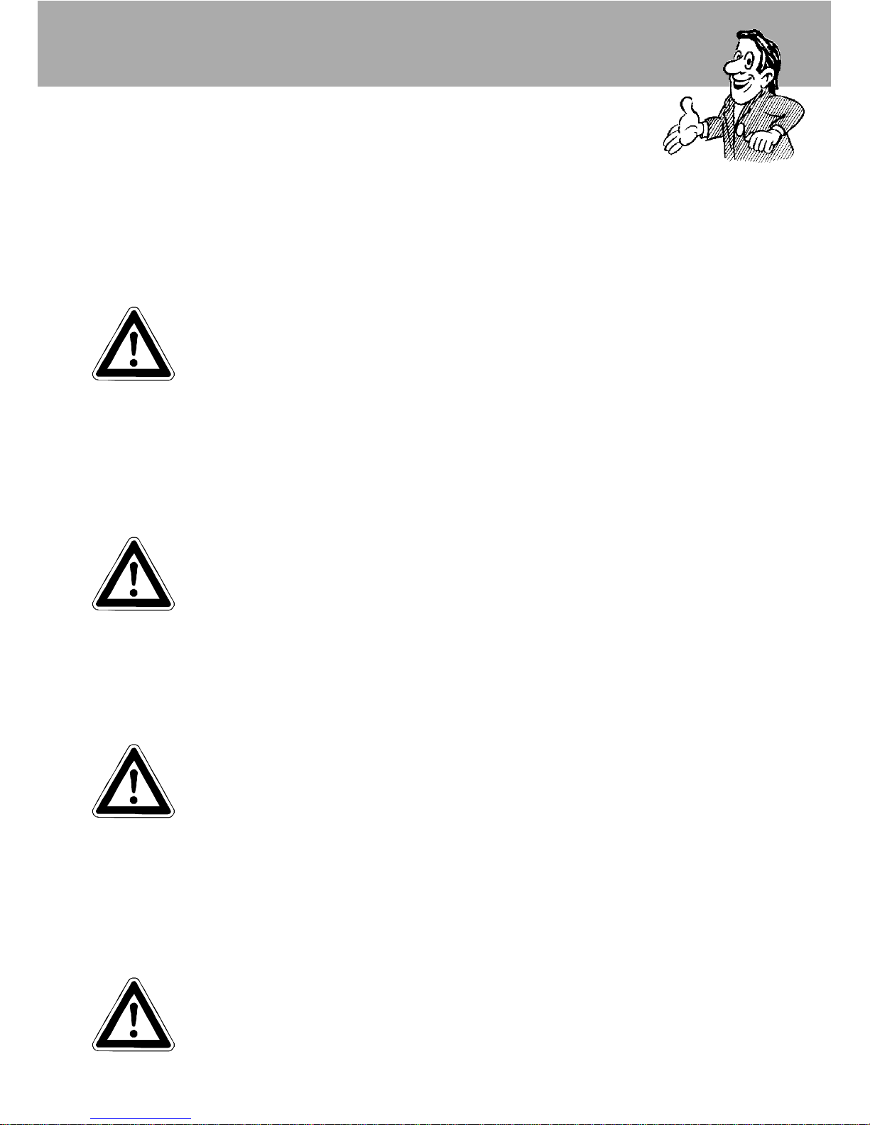
The machine can only be operated when the safety trigger is squeezed.
The machine can only be operated when the safety trigger is squeezed. When the
leve r is squeezed, the spray gun opens. The liquid is then pumped to the nozzle.
The spray pressure increases and quickly reaches the selected operating
pressure.(Not with W 11/135).
When the trigger is released, the trigger gun closes and any further spraying of
liquid from the lance is stopped and the manometer must show 0 bar.
The increase in pressure when the trigger gun is closed causes the unloader
valve-safety valve to open. The pump remains switched on and continues to
pump liquid through the pump at reduced pressure. When the trigger gun is
opened, the unloader valve - safety valve closes and the pump ressumes pressure spraying from the lance.
The trigger gun is a safety device. Repairs should only be
performed by qualified persons. Should replacement parts be
required, use only components authorized by the manufacturer.
Lance with trigger gun
The unloader valve - safety valve protects the machine from a build p of excess
pressure, and is designed not to permit an excess pressure to be selected for
operation. The limit nut on the handle is sealed with a spray coating.
The operating pressure and spray rate can be steplessly adjusted by turning the
handle.
Replacements, repairs, new adjustments and sealing should only
be performed by qualified persons.
Unloader valve - safety valve
Environmental, refuse disposal and water protection
regulations must be observed !
Page 5
5
Description
With delayed motor cut-out
Frequent, work-necessitated switching on and off of motors on
machines of this size puts a heavy load on the power network
and causes increased wear on internal electrical parts. That’s why the motor on
the new KRÄNZLE switches itself off 30 seconds after the trigger is released, and
switches itself back on again when the trigger is pressed.
When running your high pressure cleaner with hot water of 80° C
raised temperatures occur. Do not touch the machine without
safety gloves!
CAUTION !
CAUTION !
Never use liquid containing solvents such as paint thinners, petrol, oil
or similar liquid matter. Pay attention to the instructions of the
manufacturers of the cleaning agents. The seals in the machine are
not resistant to solvents. The spray of solvents is inflammable, explosive and poisonous.
Setting up
Location
Neither set up and operate the machine in rooms where there is a risk
of fire or explosion nor put it into puddles. Do not use the machine
under water.
Replacements and inspection work should only be performed by
qualified persons when the machine is disconnected from the
power supply, i.e. pull out the plug from the electrical socket.
Page 6

6
Description
Electrical connection
The machine is supplied with an electrical power cord with plug.
The mains plug must be fitted to a standard grounded socket with a
30mA residual current operated device.
The socket must be protected with a 16A delay action fuse on the
mains side.
When using an extension cable, this must have an earthed lead which
is properly connected to the socket. The conductors in the extension
cable must have a minimum cross section of 1.5 mm². Plug connections must be of a spray-proof design, and may not be located on a
wet floor.
(with extension cables of more than 10 m - 2.5 mm2 )
CAUTION !
The use of extension cables which are too long may lead to malfunctions and
start up difficulty.
Page 7

7
Description
Brief operating instructions:
1. Connect the high pressure hose with spray gun and machine.
2. Connect to suitable water supply.
3. Flush the air from the pump (open and close the spray gun several
times).
4. Make the electrical connection - (400 Volt three-phase current).
5. Switch on the machine and commence cleaning.
6. After having completed the work switch off the tap and completely empty the
pump.
(Switch on the motor for approx. 20 sec. without the water hose and gun).
Afterwards you can roll up the high pressure hose.
- Only use clean water ! - Protect from frost !
CAUTION !
Please pay attention to the regulations of your waterworks company.
In accordance with DIN 1988, the machine may not be directly connected to the
public drinking water supply lines.
A brief connection however is permissible according to DVGW (German Associa-
tion for Gas and Water Affairs) if a tube ventilator with check valve (Kränzle Order-No. 410 164) is built into the water supply.
Also indirect connection to the public drinking water supply lines is permissible by
way of free emission in accordance with DIN 1988, part 4; e.g. by using a reservoir with a float valve.
Direct connection to a non-drinking water supply line is permissible.
High pressure hose and spray device
The high pressure hose and spraying device supplied with the machine are made
of high grade material, they are also optimized for the machine and marked as
required by the appropriate regulations.
If replacement parts are required, only such parts that are authorized
by the manufacturer and which bear the markings required by the appropriate regulations may be used. The high pressure hose and spray
device must be connected in a pressure-tight manner.
The high pressure hose may not be driven over, pulled excessively, or
twisted. The hose may under no circumstances be pulled over sharp
edges, since otherwise the guarantee is automatically void.
High pressure hose lines and spraying equipment must not be repaired, but
replaced by a new hose or spraying equipment.
Page 8
8
Safety notes
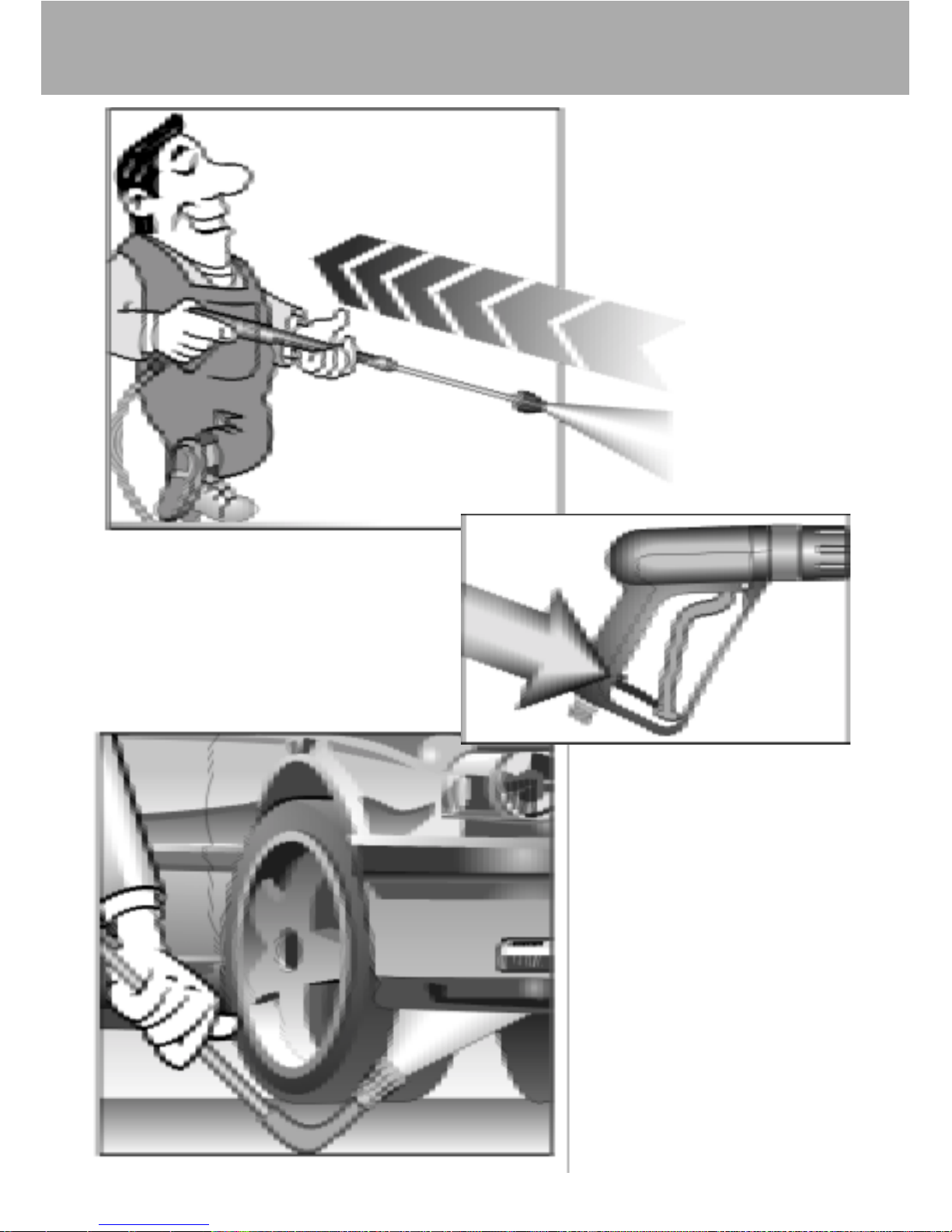
As to the recoil - see notice on page 2!
Apply the safety catch on the
spray gun after each use, in order
to prevent unintentional spraying!
Always aim the underbody
lance. Note when using an
angled underbody lance,
like for example lance No.
41.075, that there is a certain amount of torque in
the recoil.
(See also notice on page 2)
Page 9
9
Operation
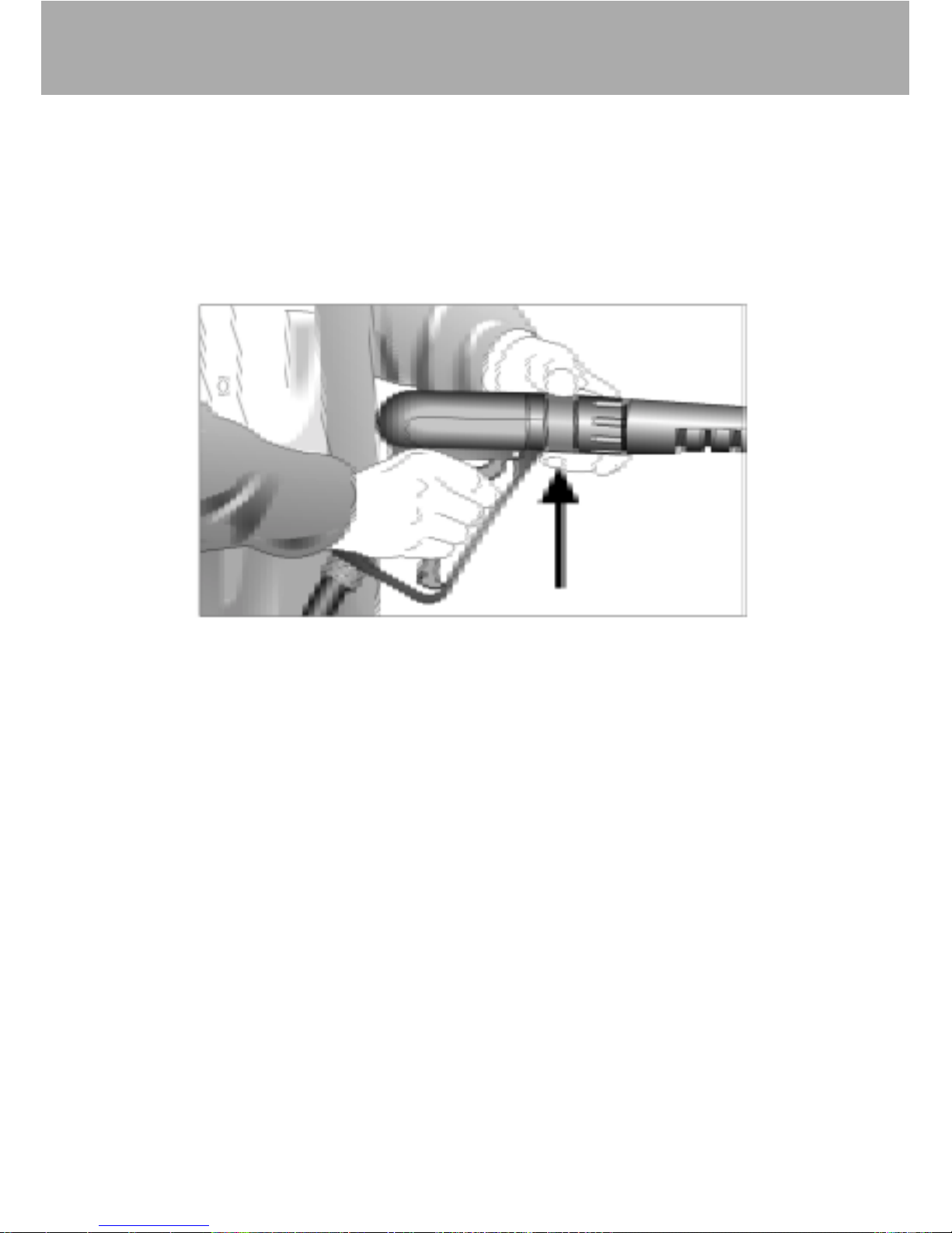
Adjusting the pressure at the gun
Simply turn the adjustment ring.
(not with W 11/135).
The machine is set to operate at maximum pressure.
Page 10
10
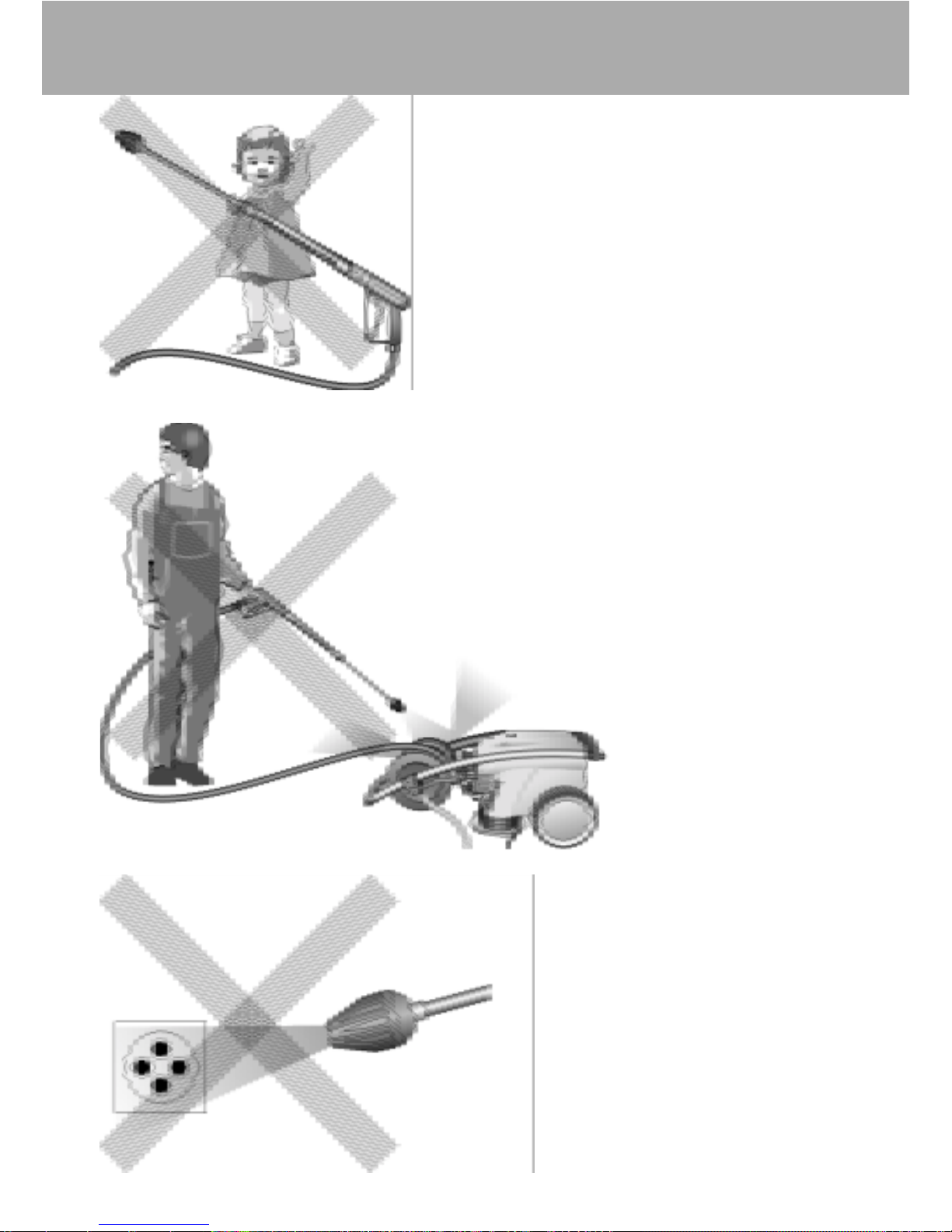
This is prohibited !
Never allow children
to use the high
pressure cleaner !
Never direct the
water jet at the
machine itself !
Never direct the
water jet at a power
socket !
Page 11

11
This is prohibited !
Do not damage the
power cord or repair
it incorrectly !
Never direct the
water jet at people or
animals !
Never pull the high
pressure hose if it has
formed kinks or
“nooses”!
Never pull the hose
over sharp edges !
Page 12

12
Valve housing
Page 13

13
Spare parts list
Spare parts list
Valve housing for AQ-pump
No Description Qty. Ord.-No
1 Ventilgehäuse 1 40.502
2 O-Ring 18 x 2 6 40.016
3 Einlaß- / Auslaß- Ventil 6 42.024
4 O-Ring 21 x 2 6 42.025
5 Ventilstopfen 6 42.026
6 Sicherungsring 4 40.032
7 Innensechskantschraube M 12 x 45 4 40.504
13 Gewebemanschette 3 40.023
14 Backring 20 mm 6 40.025
15 O-Ring 31,42 x 2,62 3 40.508
16 Leckagering 20 x 36 x 13,3 3 40.509
17 Cu-Dichtring 21 x 28 x 1,5 1 42.039
18 Gummimanschette 3 40.512
19 Verschlußschraube R 1/2" 1 42.032
20 Distanzring mit Abstützung 3 40.507
21 Cu-Dichtring 17 x 22 x 1,5 1 40.019
22 Verschlußschraube R 3/8" 1 40.018
23 Druckring 3 40.021
24 Zwischenring 3 40.516
Repair kit for sleeves and brass parts 40.065 1
consisting of: 3x Pos. 13; 6x Pos. 14; 3x Pos. 15;
3x Pos. 16; 3x Pos. 18; 3x Pos. 20; 3x Pos. 23
Repair kit for sleeves 40.517
consisting of: 3x Pos. 13; 6x Pos. 14; 3x Pos. 15;
3x Pos. 18; 3x Pos. 23
Repair kit valves 40.062 1
consisting of: 6x Pos. 2; 6x Pos. 3; 6x Pos. 4
Valve housing compl. 40.515
Page 14

14
Motor
Page 15

15
Spare parts list
Spare parts list
Motor BG 112
No Description Qty. Ord.-No
1 Stator 112 5,5 kW 400V / 50Hz 1 40.540
2 A-Lager Flansch 1 40.530
3 Rotor 112 400V / 50Hz 1 40.531
4 Lüfterrad BG112 1 40.532
5 Lüfterhaube BG 112 1 40.533
6 Klemmkasten 1 40.534
7 Flachdichtung 1 43.030
8 Lüsterklemme 2,5 mm² 4-polig 1 43.031 1
9 PG-Verschraubung PG 13,5 1 40.539
10 Kegelrollenlager 31306 1 40.103
11 Öldichtung 35 x 47 x 7 1 40.080
12 Paßfeder 8 x 7 x 32 1 40.104
13 Kugellager 6206 - 2Z 1 40.538
14 Innensechskantschraube M 6 x 30 4 43.037
16 Blechschraube 2,9 x 16 1 43.036
17 Vierkantmutter M 5 2 41.416
18 Schraube M 5 x 14 2 40.536
19 Schraube M 4 x 12 4 41.489
20 Schelle für Lüfterrad BG112 2 40.535
21 Schraube M 4 x 12 4 41.489
22 Erdungsschraube kpl. 1 43.038
Motor with terminal box 400 V / 50 Hz 24.060
Motor with terminal box 3x 220 V / 50 Hz 24.060 2
Page 16

16
Drive unit AQ
Page 17

17
Spare parts list
Spare parts list
Drive unit AQ
No Description Qty. Ord.-No
1 Ölgehäuse 1 40.501
2 CU_Dichtung 1 40.052
3 Ölablaßschraube 1 40.051
4 Innensechskantschraube M 8 x 25 6 40.053
5 Sicherungsscheibe 6 40.054
6 Flachdichtung 1 40.511
7 Öldichtung 20 x 30 x 7 3 40.044 1
8 Wellenscheibe 1 40.043
9 Axial-Rollenkäfig 1 40.040
10 AS-Scheibe 1 40.041
11.1 Taumelscheibe AQ 12,0° bei 19 l/min 1 40.042 1-12,0
11.2 Taumelscheibe AQ 10,4° bei 15 l/min 1 40.042 1-10,4
11.3 Taumelscheibe AQ 8,5° bei 13 l/min 1 40.042 1-8,5
11.4 Taumelscheibe AQ 7,0° bei 11 l/min 1 40.042 1-7,0
please specify the degree of the swash plate
12 Plungerfeder 3 40.506
13 Federdruckscheibe 3 40.510
14 Plunger 20 mm (lang) 3 40.505
15 Sprengring 3 40.048
16 O-Ring 14 x 2 2 43.445
17 Ölschauglas M 18 x 1,5 1 42.018 1
18 Flachdichtung 1 41.019 3
19 Deckel 1 41.023 1
20 Innensechskantschraube M 5 x 12 4 41.019 4
21 Ölschraube M 18 x 1,5 1 41.022 1
22 Stützscheibe für Plungerfeder 3 40.513
Drive unit complete with plunger without swash plate 40.514
Page 18

18
Power-Colt
Page 19

19
Spare parts list
Spare parts list Power Colt
W 13 / 230; W 15 / 200; W 19 / 160
No Description Qty. Ord.-No
1 Ventilkörper kunststoffumspritzt 1 12.375 1
2 Griffhülle 1 12.376
3 Regulierring 1 12.377 1
5 Lanze 1 12.379
6 Überwurfmutter ST 30 M 22 x 1,5 IG 1 13.276 1
7 Abzug-Hebel 1 12.380
8 Sicherungshebel 1 12.381
9 Regulierkolben 1 12.386
10 Außen-Sechskant-Nippel R1/4" IG 1 13.277 1
11 Parbaks 7 mm 2 15.013
12 Abschlußschraube 1 12.247
13 Stopfen 1 12.287
14 Gewindeführungshülse 1 12.250
15 Aufsteuerbolzen 1 12.284
16 Stift 1 12.148
17 Stift 1 12.253
18 Edelstahlfeder 1 12.246
19 Edelstahlkugel 8,5 mm 1 12.245
20 Edelstahlsitz 7 mm 1 13.146
20.1 Sicherungsring 1 12.258
No Description Qty. Ord.-No
21 Sprengring 1,3 x 18 1 12.384
22 O-Ring 9,3 x 2,4 1 13.273
23 O-Ring 11 x 1,44 1 12.256
24 O-Ring 3,3 x 2,4 1 12.136
26 Druckstück 1 12.252
27 Blechschraube 3,9 x 8 2 12.297
29 Aluminium-Dichtring 4 13.275
30 O-Ring 15 x 1,5 1 12.129 1
Power-colt with pressure regulation 12.390
for W 13 / 230; W 15 / 200; W 19 / 160
Power-colt without pressure regulation 12.391
for W 11/135
Repair kit
Power-colt with pressure regulation 12.299 4
consisting of 2x Pos.11; Pos. 15; Pos. 19;
Pos. 20; Pos. 20.1; Pos. 22; Pos. 23; Pos. 24;
Pos. 29; Pos. 30
Power-colt without pressure regulation 12.299
consisting of Pos. 15; Pos. 19;
Pos. 20; Pos. 20.1; Pos. 22; Pos. 23; Pos. 24;
Pos. 29; Pos. 30
Page 20

20
ULH 250
Page 21

21
Spare parts list
Spare parts list
Combi-valve ULH 250
No Description Qty. Ord.-No
1 Ventilkörper 1 14.145
2 Kolbenführung (ULH) 1 14.130
3 Steuerkolben (ULH) M 8 x 1 1 14.133
4 Eingangsstück R 3/8" IG 1 13.136
5 Ausgangsstück R 1/4" IG 1 14.136
5.1 Ausgangsstück R 3/8" IG 1 14.115
5.2 Ausgangsstück R 3/8" AG 1 14.137
5.3 Ausgangsstück ST30 M 22 x 1,5 1 14.117
6 O-Ring 11 x 1,44 1 12.256
7 Edelstahlsitz 1 14.118
8 Sprengring 1 13.147
9 Edelstahlkugel 8,5 mm 1 13.148
10 Edelstahlfeder 1 14.119
11 O-Ring 15 x 2 1 13.150
12 Rückschlagfeder 1 14.120
13 O-Ring 6 x 3 1 14.121
15 Rückschlagkörper 1 14.122
16 Parbaks 16 mm 1 13.159
17 O-Ring 15 x 2 1 13.150
19 Stopfen M 10 x 1 1 13.158
20 Parbaks 8 mm 1 14.123
21 Stopfen R3/8" 1 14.139
22 Ventilfeder bis 210 bar 1 14.125
23 Federdruckscheibe 1 14.126
24 Elastic-Stop-Mutter M 8 x 1 1 14.152
25 Sechskantmutter M 8 x 1 2 14.144
26 Nadellager 1 14.146
27 Handrad 1 14.147
28 Spanstift 1 14.148
29 Kupferdichtring 1 14.149
49 Stopfen R1/4" 1 13.387
50 Alu-Dichtring 3 13.275
Control piston, complete 14.132 2
Repair kit ULH 250 14.129
Page 22

22
Control unit
1
2
1211
3
4
5
6
7
10
9
8
Page 23

23
Spare parts list
Spare parts list
Control unit
No Description Qty. Ord.-No
1 Kabelverschraubung PG 9 1 41.430
2 Kabelverschraubung PG 16 1 41.431
3 Schütz 400 V 1 41.432
3.1 Schütz 230 V 1 41.432 1
4 Motorschütz 10-16 A 400 V 1 13.433
4.1 Motorschütz 16-24 A 230 V 1 41.433 1
5 Lampe rot kpl. 1 41.434
6 Lampe grün kpl. 1 41.435
7 Ein- /Aus-Schalter kpl. 1 41.436
8 Schütz 400 V 1 41.437
8.1 Schütz 230 V 1 41.437 1
9 Zeitrelais 1 41.438
10 Gehäuse 1 41.439
11 Widerstand 10 kΩ 1 41.440
12 Feinsicherung 2 Ampère 1 41.441
Control unit complete for 400 V / 50 Hz 40.309 4
Page 24

24
Hose screw connection
1
2
3
3
4
5
6
7
8
8
8
8
9
10
10
10
11
23
22
21
20
19
18
12
13
14
15
16
17
Page 25

25
Spare parts list
Spare parts list
Hose screw connection
No Description Qty. Ord.-No
1 Abstandsrohr 1/4" AG x 1/4" AG 1 41.039
2 Winkel 1/4" IG x 1/4" IG 1 41.445
3 Doppelnippel 1/4" AG x M 18 x 1,5 AG 1 41.446
4 By-Pass-Schlauch 1 41.447
5 Doppelnippel 3/8" AG x M 18 x 1,5 AG 1 13.288
6 Verschraubung 3/8" AG x M 18 x 1,5 IG 1 41.448
7 ULH 250 1 14.141
8 Dichtring 1 12.129
9 Durchflußwächter 1 12.634
10 Doppelnippel 3/8" AG x 3/8" AG 1 41.449
11 ST30 Nippel 3/8" IG x M 22 x 1,5 AG 1 13.369
12 Winkel 1/4" AG x 1/4" AG 1 41.450
13 Manometerschlauch 1 41.451
14 Nippel 1/4" IG x 1/4" AG 1 41.452
15 Alu-Dichtring 3 13.275
16 Klemmring 1 15.039 9
17 Manometer 1 15.039
18 Winkel 1/2" x M 18 x 1,5 1 41.453
19 Wassereingangsschlauch 1 41.454
20 Doppelnippel 1/2" AG x M 18 x 1,5 AG 1 41.455
21 Schmutzfänger 1/2" IG x 1/2" IG 1 13.299
22 Reduzierring 1/2" AG x 3/8" IG 1 12.019
23 Sauganschluß 3/8" IG x 3/4" AG 1 41.708
Page 26

26
Standard Vario-Jet Nozzle
No Description Qty. Ord.-No
30 Nippel ST30 M22x1,5 AG / M 12 x 1 1 13.363
31 Rohr 400 mm, bds. M 12 x 1 1 15.002
32 Regeldüse mit Regulierring 1 13.201 2
33 Flachstrahldüse 1
Please specify nozzle size:
D25045 with W 11 / 135
D25045 with W 13 / 230
D2505 with W 15 / 200
D2507 with W 19 / 160
Spare parts list Lance with
Standard vario-jet nozzle
Page 27

27
Wiring diagram
Inlet line
Motor
S1 Contact element
F1 Motor protection relais
Through-flow
detector
Malfunction
Operation
blue
brown
brown
brown
Page 28

28
Wall mounting
35 mm
4
2
0
m
m
340 mm
35 mm
10 mm O
730 mm
330 mm 330 mm
( für 8 mm Schrauben )
(For 8 mm screws)
Page 29

29
General rules
Inspections
The guarantee period is 12 months according to VDMA.
The guarantee is void if changes are made to the safety devices or if the machine
is used at excess temperatures or speeds. The guarantee is also void if the
machine is used with a voltage below the required rating, with less than the
required amount of water, with dirty water and external damage to the pressure
gauge, nozzle, high pressure hose and spray device.
This guarantee is not applicable for spare parts.
Our operating instructions must be complied with.
Accident prevention
The machine must be inspected according to the “Guidelines for Liquid Spray
Devices” at least once every 12 months by a qualified person, to ensure that
continued safe operation is guarateed.
The results of the inspection are to be recorded in writing.
This may be done in any form.
The machine is designed for accidents to be impossible if used correctly.
The operator is to be notified of the risk of injury from hot machine parts and the
high pressure water jet. The “Guidelines for Liquid Spray Devices” must be
complied with.
Check the oil level at the oil dip stick prior to each use.
(Ensure horizontal position!)
Oil change:
The oil in your high pressure pump should be changed after approx. 40 hours of
operation, or if it takes on a grey or whitish colour. (Formation of condensate)
The oil must be collected in a container and disposed of in accordance with local
rules or legislation.
New oil: 1,0 l - Motor oil: W10-60 SAE Semi-synthetic oil
Ord.-Nr.: 40.059 1
Guarantee
Page 30

30
for KRÄNZLE - High Pressure Cleaners
Regular inspection every 12 months if used professionally!
Appliance No: Type:
The following must be checked:
1. Safety features
a) Manometer
b) Safety valve (pressure control)
c) Operating pressure
d) Cut out pressure (max. 10% above
operating pressure)
e) Low pressure with trigger released
2. General condition
a) High pressure hose
b) Cable, plug, switch (VDE)
c) Spray gun
d) Motor
e) Oil level
Result of inspection: Date of inspection:
Faults rectified,
Stamp and signature
Excerpt from the Guidelines for Liquid Spray Equipment (ZH 1/46) by the Central Office of the Professional
Trade Association.
Inspection:
Liquid spray equipment should be inspected for safe operation by a qualified person whenever necessary,
but no less than every 12 months. The maker’s or supplier’s instructions must be followed. The inspection
intervals may be extended if the equipment is not in active use.
In Germany, inspections compliant with the (German) Emission Controls Act may be required for oil and
gas-fired equipment, and the owner must arrange for these to be carried out independently of the main
inspection.
The results of inspections must be recorded in writing and presented to the respective authorities on
demand. There is no set form for these records.
The information in the operating instructions are a part of the inspection
Inspection report
Page 31

(Managing Director)
Herewith we W 11 / 135, W 19 / 160,
declare that W 15 / 200, W 13 / 230
complies with the following 91/368 EEC Ann. I N° 1
provisions applying to it 73/23 EEC
79/113 EEC 81/1051 EWG
Applied EN 292 T 1 and T 2
harmonized standards EN 60 204 T 1
in particular EN 50 082-2
EN 61 000 3-2 3-3 4-12
EN 55 014
EN 55 104
Applied national technical DIN VDE 0700 Part 265/79 3.95
standards and specifications DIN IEC 61 S (Co) 17
in particular DIN IEC 801 2-6 601 1-2
DIN IEC 1000 4 2-11
Notified body
1)
within the TÜV Hanover
meaning of Annex VII
engaged for
2)
- safe keeping of the file as defined by Annex VI
- verification of correct application of harmonized standards and certification
of adequacy of the file as defined by Annex VI
- EC type-examination (EC type-examination certificate No. ...)
Bielefeld, 10/10/97
I. Kränzle GmbH
Elpke 97 . 33605 Bielefeld
EC declaration of conformity as
defined by machinery directive 89/392/EEC Annex II A and
the EC low-voltage directive 73/23 EEC and the
EC-EWV directive 89/336 EEC
Hochdruckreiniger
High-pressure-cleaners
Nettoyeurs à Haute Pression
Page 32

Reprint only allowed with the authorization of
As of date of 13. 09. 1999
Ord.-No: 30 242 1
 Loading...