

Kranzle therm 601 E-ST 18, therm 891 E-ST 48, therm 601 E-ST 24, therm 601 E-ST 36, therm 871 E-ST 48 Operating Manual
Page 1
www.kraenzle.com
therm 601 E-ST 18
therm 601 E-ST 24
therm 601 E-ST 36
therm 871 E-ST 48
therm 891 E-ST 48
Operating manual
High pressure cleaner
- GB -
Read and conform safety instructions before use!
Keep instructions in a safe place for later use and
pass them on to any future user.
Page 2

Contents
Contents ................................................................................................................ 2
Overview ’This is what you have purchased’ ................................................................. 4
Description of appliance ................................................................................................ 5
Technical data .............................................................................................................. 6
General rules ................................................................................................................ 8
Safety precautions – accident prevention ................................................................. 8
Water connection – electrical connection ......................................................................11
Putting into operation ................................................................................................ 12
Usage as a cold water high pressure cleaner ....................................... 13
Usage as a hot water high pressure cleanerr ........................................ 13
Kränzle- technology ................................................................................................... 14
Water and cleaning system ................................................................... 14
Lance and spray gun ............................................................................. 14
Total stop system ................................................................................... 14
High pressure hose and spray device ................................................... 15
Pressure control valve – safety valve .................................................... 15
Thermostat ............................................................................................ 16
Electric heating ...................................................................................... 18
Suction of detergents ................................................................................................... 19
Decommissioning - frost protection .............................................................................. 20
Care and Maintenance (weekly/yearly) ...................................................................... 22
Changing the oil .................................................................................... 21
Decalcifying the continuous-flow heater ................................................ 22
Particular rules, directives and inspections .................................................................. 23
Troubleshooting ......................................................................................................... 24
Small repairs – do it yourself ...................................................................................... 26
2
Page 3

3
Page
Spare parts lists .........................................................................................................28
Water inlet .............................................................................................28
Water supply ..........................................................................................29
Heating module 18/24 kW .....................................................................30
Heating module 36/48 kW .....................................................................31
Electric module 18/24 kW ......................................................................32
Electric module 36/48 kW ......................................................................34
Engine bearing ......................................................................................36
Unloader valve and pressure switch ......................................................38
Pump .....................................................................................................42
Pump motor ...........................................................................................46
Valve housing ........................................................................................48
Electronics switchbox ............................................................................50
Safety valve ...........................................................................................52
Flow monitoring device ..........................................................................53
Gun 'Starlet' ...........................................................................................54
Pipeline plan ..............................................................................................................55
Wiring diagram 18/24 kW.............................................................................................56
Wiring diagram 36/48 kWl ............................................................................................57
Inspection reports- attestation form .............................................................................58
EG – Declaration of Conformity ...................................................................................68
Guarantee ..............................................................................................................59
Page 4
4
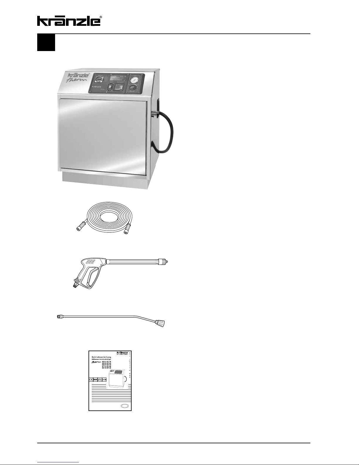
This is what you have purchased
1.
Kränzle hot water high-pressure cleaners
therm E-ST, electrically heated
2.
Steel-fabric high-pressure
hose, 10 m, NW 8
3.
Safety spray gun with insulated
handle and screw connection
4.
Spray lance
5.
Operating manual
Page 5
5
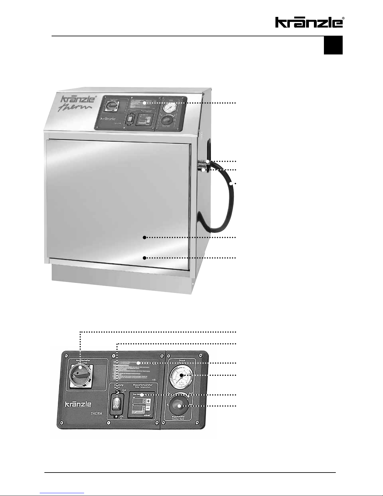
Operating panel
Water inlet with filter
High-pressure outlet
3 m power lead (without plug)
Front door, lockable
Stainless steel housing
Description of appliance - Kränzle therm E-ST
Master switch (appliance ON-OFF)
Heating switch (burner ON/OFF)
Brief operating instructions
Pressure gauge – high pressure
Digital thermostat for adjusting
water temperature
Detergent switch (ON-OFF)
Page 6

6
Technical data
Operating pressure, continuously adjustable
30 - 100 bar
(nozzle 25045)
30 - 100 bar
(nozzle 25045)
Operating pressure, continuously adjustable
30 - 160 bar
(nozzle 2503)
30 - 160 bar (nozzle 2503)
Admissible overpressure, nozzle size 25045 120 bar 120 bar
Admissible overpressure, nozzle size 2503 170 bar 170 bar
Water output 180 - 600 l/h 180 - 600 l/h
Maximum hot water discharge 60 °C at 32 bar 72 °C at 32 bar
Sucked in water is heated by 26 °C with 10 l/min by 26 °C with 10 l/min
Maximum water inlet temperature 60 °C 60 °C
Steel fabric high-pressure hose 10 m 10 m
Connected load 400 V, 32,6 A, 50 Hz 400 V, 41,2 A, 50 Hz
Wattage 20,6 kW 26,6 kW
Heating output 18 kW 24 kW
Fuse 50 A 63 A
Protection type IP 54 IP 54
Weight 220 kg 220 kg
Dimensions in mm (W x D x H) 800 x 650 x 950 800 x 650 x 950
Order No. 41.358 5 41.358 6
therm 601 E-ST 18 therm 601 E-ST 24
Page 7

7
30 - 100 bar (nozzle 25045) 30 - 170 bar (nozzle 2505) 30 - 220 bar (nozzle 2505)
30 - 160 bar (nozzle 2503)
120 bar
170 bar
180 - 600 l/h 180 - 870 l/h 180 - 900 l/h
80 °C at 32 bar 80 °C at 32 bar 80 °C at 32 bar
by 50 °C with 10 l/min by 46 °C with 14 l/min by 46 °C with 15 l/min
60 °C 60 °C 60 °C
10 m 10 m 10 m
400 V, 58,6 A, 50 Hz 400 V, 80 A, 50 Hz 400 V, 80 A, 50 Hz
38,6 kW 53,5 kW 53,5 kW
36 kW 48 kW 48 kW
80 A 80 A 80 A
IP 54 IP 54 IP 54
220 kg 220 kg 220 kg
800 x 650 x 950 800 x 650 x 950 800 x 650 x 950
41.358 7 41.358 9 41.358 8
Permissible tolerance for figures ± 5 % in acc. with VDMA uniform sheet 24411
therm 601 E-ST 36 therm 871 E-ST 48 therm 891 E-ST 48
Page 8
Range of application
This machine may only be used for cleaning facades, vehicles, containers, pavement
slabs, stables, machines and similar objects.
Inspections
The machine must be inspected according to the “Guidelines for Liquid Spray Devices” at
least once every 12 months by a qualified person, to ensure that continued safe
operation is guaranteed. The results of the inspection are to be recorded in writing. This
may be done in any form. For inspection reports see pages 48/49.
High-pressure cleaners used for commercial purposes have to be
checked by a qualified person at least every 12 months!
Accident prevention
The machine is designed for accidents to be impossible (if used according to these
instructions). Please read safety notes included in these instructions carefully before using
the machine and act correspondingly. Operating staff has to be instructed according to
this manual. The “Guidelines for Liquid Spray Devices” must be complied with.
Setting up - Location
Neither set up and operate the machine in rooms where there is a risk
of fire or explosion nor put it into puddles. It is prohibited to use the
machine under water.
Do not jam the trigger of the gun during operation!
When carrying through service and maitenance tasks the machine has
to be cut off the power supply system. Put main switch to "0" and pull
plug out of socket
.
Never operate the machine if cables or other safety-relevant parts (e.g.
excess pressure valve, high-pressure hose, spraying devices, etc.) are
defective.
8
General rules
Safety notes
Page 9
9
Safety notes
Never operate the machine without supervision. The machine may only
be operated by persons who have been instructed accordingly.
Some parts inside the machine, all water conducting components and all
metal parts of gun and lance are hot during hot water operation. Keep all
hoods and protective covers closed during operation and never touch
any metal parts of gun or lance.
Persons operating the machine should wear the necessary protective
clothing, i.e. waterproof clothing, rubber boots, safety goggles, headwear
etc. It is prohibited to use the machine in close vicinity to people lacking
suitable protective clothing.
The high pressure spray can generate a high level of noise. If noise
exceeds the maximum allowed levels, users and others in the vicinity
must wear suitable ear protection
.
Do not spray against matter containing asbestos or other hazardous
substances.
For safety reasons always switch the main switch to "0"- postion after
having finished the cleaning task (disconnection from power supply).
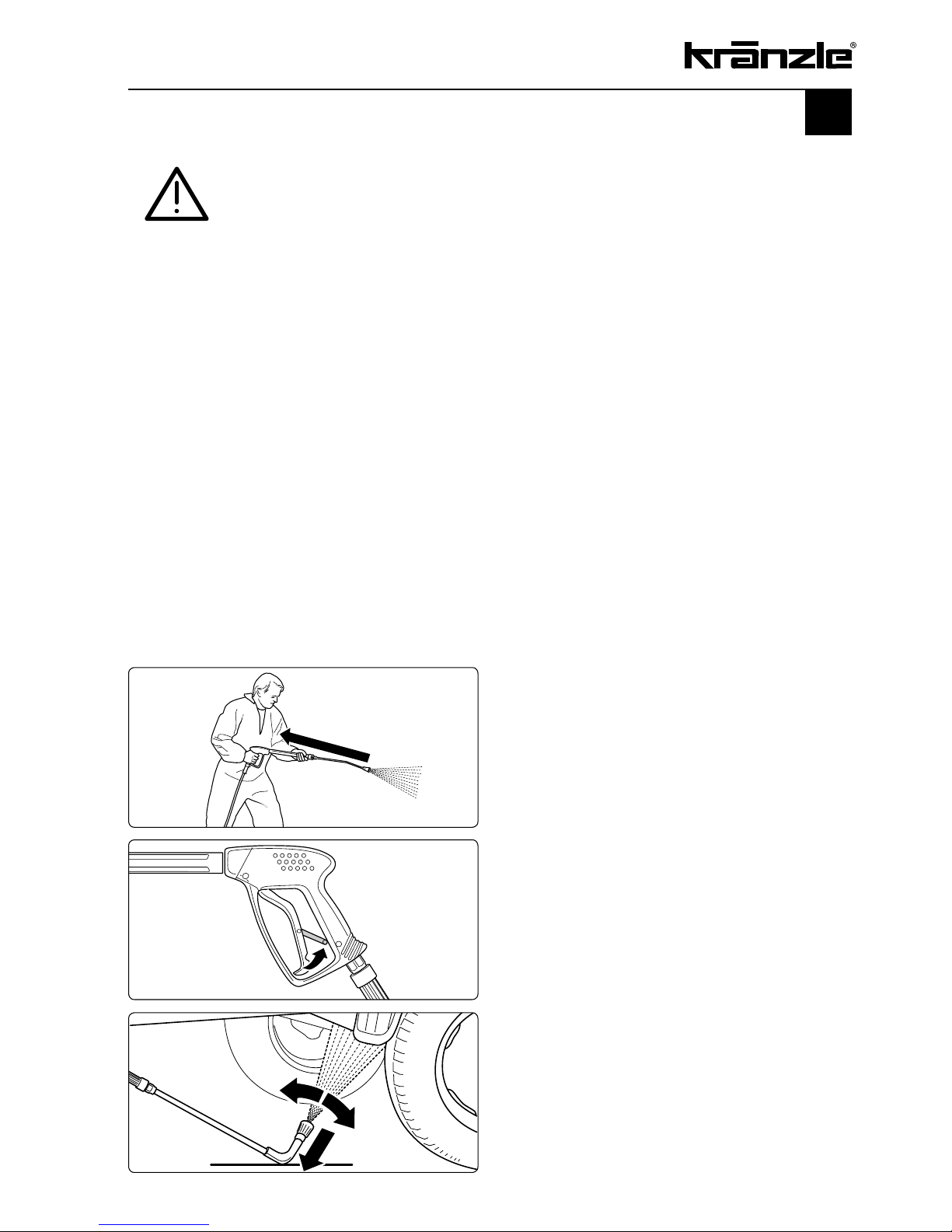
Bear in mind that during cleaning tasks
with a high-pressure water jet a significant
recoil at the lance arises.
Additionally angled lances produce a
clearly perceivable amount of torque.
Apply the safety catch on the spray gun
after each use, in order to prevent
unintentional spraying!
Always aim the underbody lance! Bear in
mind when using a curved or angled
spraying lance that there is a significant
amount of torque in the recoil!
Page 10
10
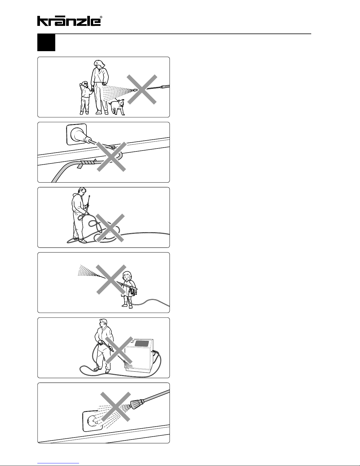
Safety notes - This is prohibited!
Never allow children to use the high
pressure cleaner!
Never direct the water jet at the
machine itself!
The machine may not be placed within
reach of the water jet spray mist!
Never direct the water jet at a power
socket!
Never direct the water jet at people
or animals!
Only use power cables which are in
perfect working order! Do not damage
the power cable or repair it incorrectly!
Never pull the high pressure hose if
it has formed kinks or “nooses”!
Never pull the hose over sharp edges!
Page 11

11
Connection to water supply
Please pay attention to the regulations of your waterworks company! In accordance
with DIN EN 61770, the machine may not be directly connected to the public drinking
water supply lines. A brief connection however is permissible according to DVGW
(German Association for Gas and Water Affairs) if a tube ventilator with check valve
(Kränzle Order-No. 41.016 4) is built into the water supply. Also indirect connection to
the public drinking water supply lines is permissible by way of free emission in
accordance with EN 61 770; e.g. by using a reservoir with a float valve. Direct
connection to a non-drinking water supply line is permissible.
Electrical connection
The voltage given on the specification plate must match the mains
voltage.
The machine is supplied with power cable without plug. The plug has to be equipped with a safety earth terminal and a 30 mA residual-current circuit breaker.
The mains connection has to be fused with a time-delay fuse according to the
specifications on page 6/7.
If an extension cable is used, it must have an earth line that is properly connected to the
plug connections. The conductors in the extension cable must have the following minimum cross section:
at 18 kW - 6 mm
2
at 24 kW - 10 mm
2
at 36 kW - 16 mm
2
at 48 kW - 25 mm
2
Extension cables that are too long cause a drop in voltage and thus
malfunctions. If you are using a cable drum, the cable must always
be fully unwound.
Page 12
1.
Connect to power circuit. Make sure that the main switch is in "OFF" position.
2.
Connect machine to water mains (2 - 8 bar pre-pressure). Inside diameter of hose
minimum 1/2 ". The water storage tank fills with water. The float valve shuts the water
intake as soon as the tank is full.
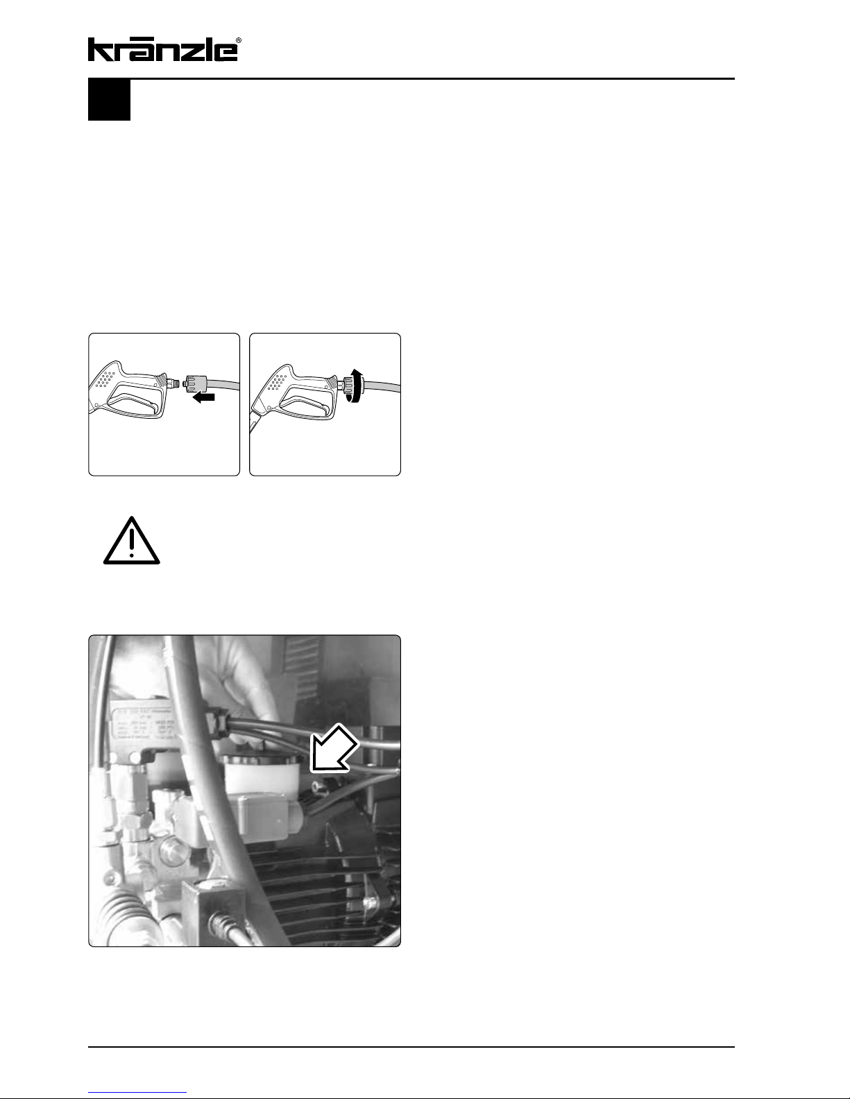
3.
Fasten high-pressure hose to appliance
4.
Push on HP hose to gun.
5.
Screw together HP hose and gun
pressure-tightly.
12
Putting into operation
6.
Always check oil level prior to
operation! Open the HP cleaner.
Do not start the machine if the oil level is not
between the two markings on the oil-level
glass. Refill with oil if necessary.
See page 23.
Take care that all screw connections are pressure-tight. A leakage
of gun, high-pressure hose or hose drum has to be repaired at once.
Leakages lead to an increased wear and guarantee is void if
consequential damages occur.
Page 13

1.
Ignition switch to -OFF- position
Detergent valve must be closed!
(Switch in left end stop position)
2.
Switch on main switch with disengaged
spray gun. Vent high-pressure cleaner: Pull
and release trigger of spray gun various
times.
Start cleaning task.
Usage as a cold water high-pressure cleaner
1.
a) Temperature mode: Set required tem-
perature at the thermostat.
(Min. temperature 40 °C)
b) Percentage mode: Set percentage
value for heating output.
2.
Switch on main switch with disengaged
spray gun. Vent high-pressure cleaner:
Pull and release trigger of spray gun
various times.
Detergent valve must be closed!
(Switch in left end stop position)
3.
Start ignition. The water is heated up
and constantly kept at the set
temperature.
Start cleaning task.
Usage as a hot water high pressure cleaner
13
Page 14
14
Water and cleaning system
The water is fed to the high-pressure cleaner under pressure (2-8 bar pre-pressure).
A float valve regulates the water flow in the storage tank. Then the water is sucked
directly from the storage tank by the high-pressure pump and forced with the adusted
pressure through the heat exchanger to the safety spray lance. The high pressure jet
is formed by the nozzle at the end of the safety lance.
Environmental, refuse disposal and water protection regulations
must be observed!
Kränzle technology
Lance with trigger gun
The machine can only be operated when the safety trigger is squeezed. When the lever
is squeezed, the spray gun opens. The liquid is then pumped to the nozzle. The spray
pressure increases and quickly reaches the selected operating pressure. When the
trigger is released, the trigger gun closes and any further spraying of liquid from the
lance is stopped. The motor stops.
When actuating the gun once more the pressure control valve - safety valve closes and
the motor is started again. The pump resumes feeding water to the spraying lance with
the selected operating pressure. When the gun is closed, the water hammer opens the
pressure control valve - safety valve and the motor is switched off by the pressure
switch.
The trigger gun is a safety device. Repairs should only be performed
by qualified persons. Should replacement parts be required, use only
components authorized by the manufacturer.
Total stop system
The machine is fitted with a Total-Stop-System. If the gun is closed for longer than
approx. 20 seconds, the machine switches off automatically, after 20 minutes the
machine moves to safety switch off and you must use the main switch to turn it back on.
The machine restarts automatically when the gun is operated, provided that the master
switch is on.
Page 15
15
High pressure hose and spraying device
The high pressure hose and spraying device supplied with the machine are made of high
grade material, they are also optimized for the machine and marked as required by the
appropriate regulations.
If replacement parts are required, only such parts that are authorized
by the manufacturer and which bear the markings required by the
appropriate regulations may be used.
The high pressure hose and spray device must be connected in a
pressure-tight manner.
The high pressure hose may not be driven over, pulled excessively, or
twisted. The hose may under no circumstances be pulled over sharp
edges, since otherwise the guarantee is automatically void.
Hoses are wearing parts. The guarantee only covers defects of
fabrication no external damages whatsoever.
Defective high-pressure hoses and spraying devices may not be
repaired. They always have to be replaced.
Pressure control valve-safety valve
The pressure control valve allows full adjustment of water quantity and pressure. The
safety valve protects the machine from excessive pressure and cannot be adjusted
beyond the admissible operating pressure. The setting nuts are sealed with lacquer
.
Replacements, repairs, new adjustments and sealing operations may
only be performed by trained personnel.
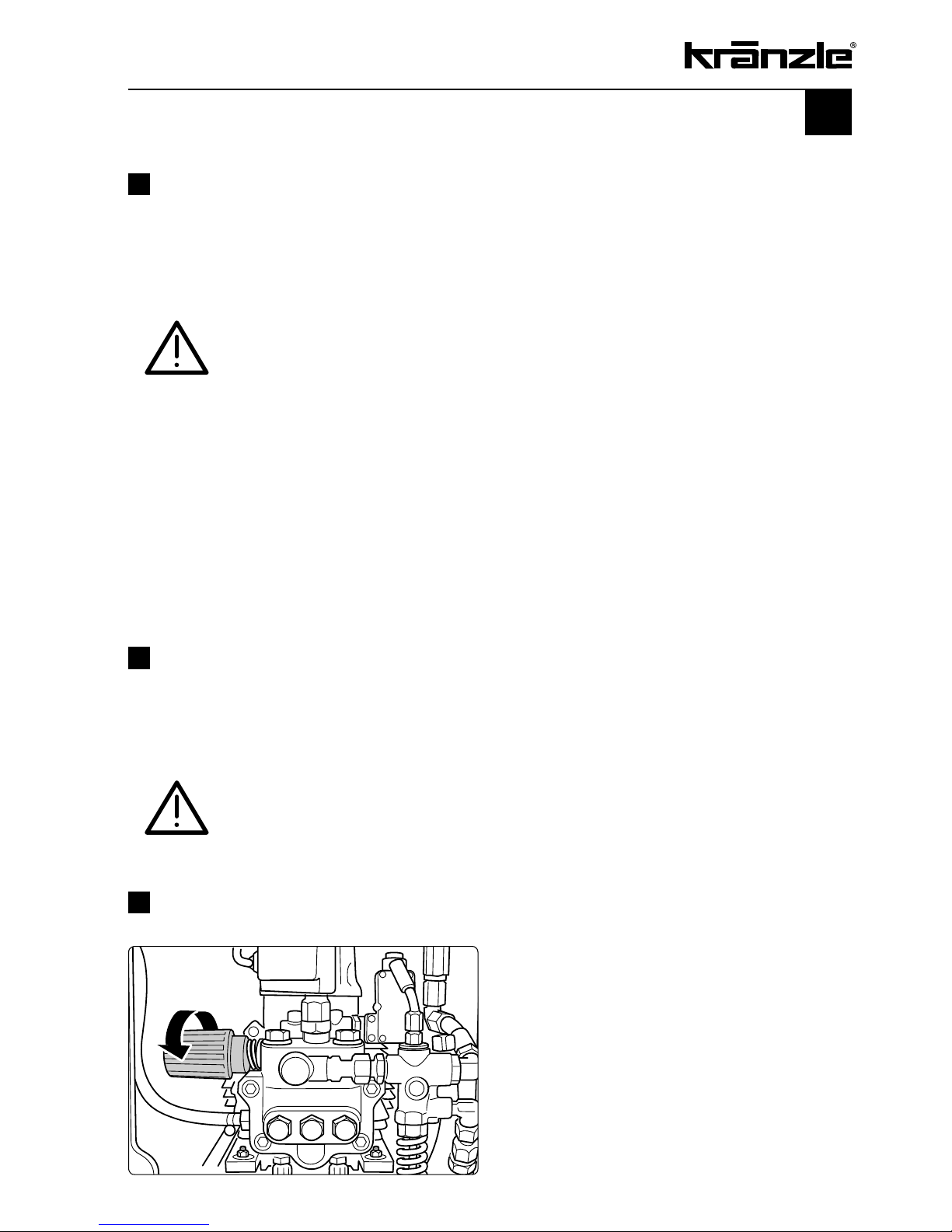
Adjustment of pressure, quantity and temperature
The operating pressure, the water
flow and correspondingly the water
temperature ist controlled by the
pressure control valve.
A right-hand turn increases the
pressure, a left-hand turn decreases
the pressure.
Page 16
16
Kränzle technology
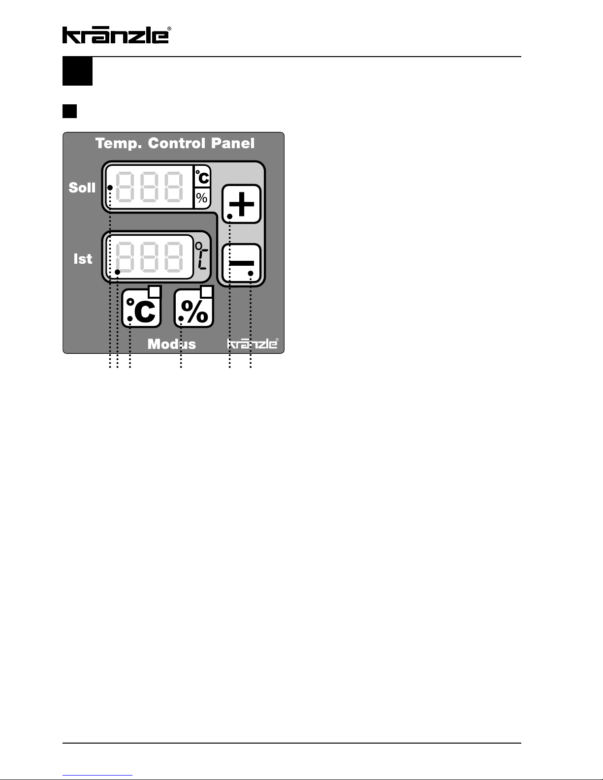
The thermostat controls the spray water
temperature.
After you switch on the device, "888"
appears in both displays for approx. 1
second as a test of the functioning of the
displays.
Thermostat
12 3 4 5 6
The thermostat has two operating modes:
1. Temperature mode
This mode is always activated when the unit is switched on or can be selected using
the "°C°" button (Pos. 3). The red LED above the "°C" button and next to the set
temperature display lights up. The desired "Set" temperature is set using the two buttons
(+/-, Pos. 5+6) and can be read in the upper display (Pos. 1). If you press the button for
a longer time, the set temperature is quickly adjusted in 5°C increments.
The last set value set is also stored after the unit is switched off and is available again
immediately after switching back on.
The current spray temperature can be read from the bottom display (Pos. 2).
2. Percentage mode
This mode is activated by pressing the "%" button (Pos. 4). The yellow LED above the
"%" button and next to the set temperature display ashes.
In the temperature control system in conventional high pressure cleaners, and in
temperature mode for this unit, the water temperature is measured at the outlet of the
heater, and the heater is switched on an off according to the temperature desired by the
user. Due to the large amount of water in the heating coil, it takes a long time until the
temperature sensor registers that the burner has switched on and the desired temperature
has been reached. This means that the temperature increases far above the desired value
or falls far below the desired value.
Page 17
17
Thermostat - Percentage mode
The innovative new percentage mode now lets the user specify the switching duration
of the heater in percent using the "+" and "-" buttons (Pos. 5+6) (100% being the max.
temperature) rather than setting the desired temperature. Now the result of the setting
must be checked by using the "Actual" temperature display. If the desired temperature has
not yet been reached, the percentage must be increased.
By setting percentages of the heating duration, the temperature of the high pressure jet is
kept constant in a very narrow range.
The last value set is also saved after the unit is switched off in percent mode.
Operating hour meter
The cleaner is equipped with an operating hour meter.
If during normal operation the momentary operating mode button ( "°C" or "%" ) is actuated for
more then 2 seconds, the operating time of the pump is displayed for 5 seconds and afterwards the
combustion time for 5 seconds as well. Thereafter the display shows the original values again.
As long as the operating hours are displayed no further inputs on the monitor are possible.
The operating time is displayed in hours [ h ] either in the “TARGET” or in the „ACTUAL“
window. The 1000 and 100 hours are displayed in the „TARGET“ window and the 10, 1 and
1/10 hours in the “ACTUAL” window:
Pump operating time: Target-Display: P 9 9 Actual-Display: 9 9. 9 for 9 999.9h
Combustion time: Target-Display: F 9 9 Actual-Display: 9 9. 9 for 9 999.9h
e.g.: F00 27.3 = Cumbustion time 27 hours and 18 minutes
Displayed malfunctions
Display as follows
Cause Action
SOLL IST
Err OFF
Water temperature at
heating chamber outlet
above 147 °C
Operate appliance without heating „Heating
OFF“ until the temperature has dropped
below 147°C. Switch main switch „OFF“ and
then back „ON“ again
AUS
(OFF)
E7
Appliance has not been
operated for more than 20
minutes
-> Safety cut-off
Switch main switch „OFF“ and then back
„ON“ again.
Err E2
Temperature sensor
defective
Replace temperature sensor
Page 18
18
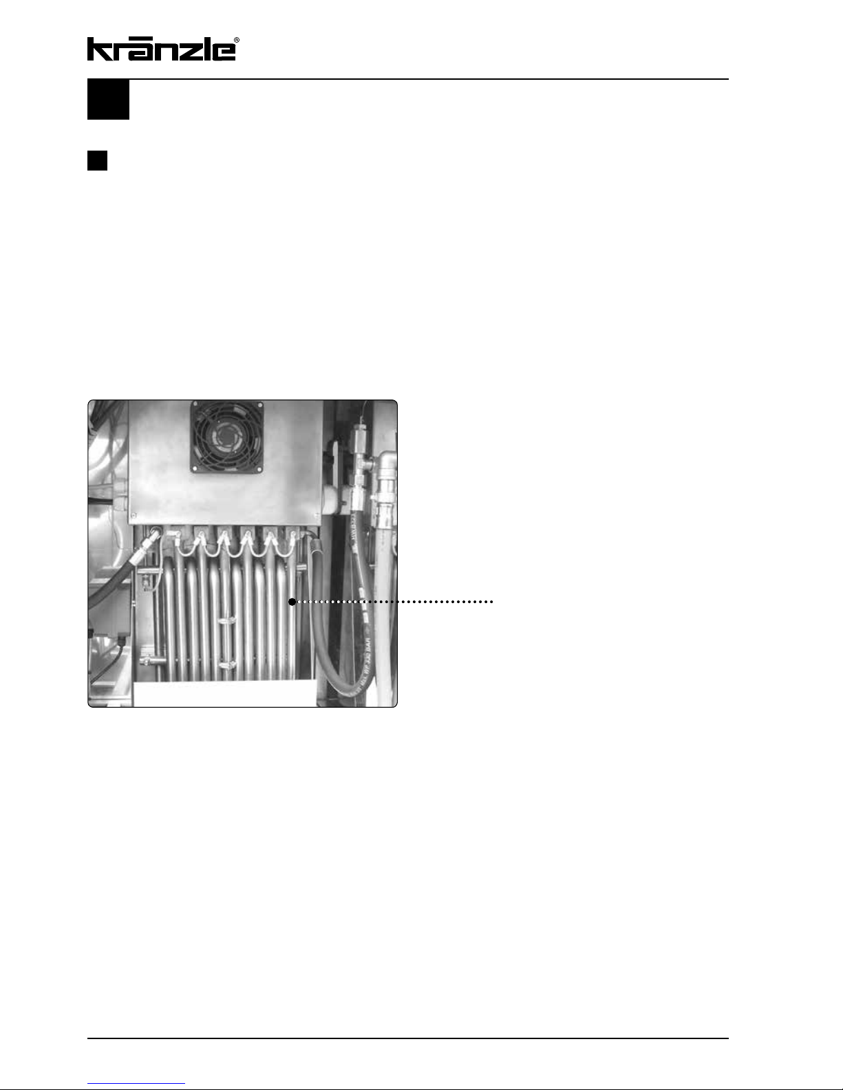
Kränzle technology
Electric heating 18, 24, 36, 48 kW
The flow heaters are connected in series in modular design according to machine type
and kW output.
For water temperature at max. water output we refer to the table on pages 6/7, second
column „Heating of sucked in water“.
To be able to reach the maximum hot water output temperature it might be necessary to
reduce the operating pressure, thus reducing the water output in l/min at the same time
(see page 15).
For the temperature values we refer once more to the table on page 6/7, see „max. hot
water output“.
Flow heater
Page 19

Detergent supply from the suction side:
Detergent injection on the pressur side, as you probably know it from other HP cleaners,
consume approx. 30 % of the cleaning energy, no matter if they are used or not. Due to the
water tank fitted to the Kränzle therm cleaners it is now possible to directly suck the
detergent into the pump thus reducing output loss and increasing the efficency
considerably.
The detergents are applied without having to reduce the working
pressure.
Only open the dosing valve, if the detergent sieve is placed in a
liquid. Sucked air leads to destruction of the pump seals! No
guarantee!
Keep detergent-ph-value neutral 7 - 9!
Observe specifications of detergent manufacturer!
e.g.: protective equipment, rules for waste water treatment etc.
Never suck in liquids containing solvents like varnish solvents,
petrol, oil or similar liquid! Observe specifications of detergent
manufacturers
!
Seals inside the appliance are no resistant against solvents! The spray
mist of solvents is highly inflammable, explosive and poisonous.
19
Suction of detergents
1.
Place detergent filter into detergent
container.
2.
Dosing of detergent is done by turning
the detergent valve.
3.
By closing the detergent valve the
supply of detergent is stopped.
4.
After having used detergents rinse the
appliance with open spray gun and clean
water for at least 2 minutes.
Page 20

20
Decommissioning - frost protection
1. Switch off the machine - main switch to „0“- position
2. Cut off the water supply
3. Open the spray gun briefly until the pressure is released
4. Apply the safety catch on the spray gun
5. Remove the water hose and spray gun
6. Drain the pump: switch on the motor for approx. 20 seconds
7. Pull the plug from the socket
8. Clean HP hose and stow away
9. Clean water filter
Frost protection
The machine is normally still partially filled with water after work has been completed.
In case the high-pressure cleaner is exposed to frost:
To protect the appliance from frost, completely empty it of water:
Disconnect the machine from the water supply and switch off the ignition. Switch on the
master switch and open the gun. The pump now presses the remaining water out of the
water tank, the pump and the continuous-flow heater.
Do not allow the machine to run for longer than a minute without water.
If the machine is not in use for lengthy frosty periods of time, it is advisable to pump
anti-freeze into the machine: For this purpose, fill the antifreeze agent into the water
tank and switch on the machine without ignition. Wait with opened gun, until the agent
comes from the nozzle.
However, the best protection against frost is to keep the machine in a place that is
safe from frost.
Page 21

21
Change the oil:
First oil change after approximately
50 operating hours. Thereafter the oil
should be changed every 500 operating
hours or yearly.
Take the oil drainage hose, which is
connected to the oil drainage screw from the
inside of the appliance.
Open the red oil ller plug at the top side of
the black oil housing.
Open the cap at the end of the hose. Drain
off the oil into an oil pan and dispose of it
responsibly. Close the end of the hose. Rell
with new oil.
Weekly, or after approx. 40 hours of operation:
- Check the oil level of the high pressure pump. If the oil level is too low, add oil until
the oil level is between the two markings on the oil measuring rod.
Change the oil if it has a grey or whitish appearance. The oil should be
disposed of responsibly.
- Check the water filter in front of the float valve in the water tank and the fuel filter
in front of the solenoid valve. Clean the filters if necessary.
Yearly, or after approx. 500 hours of operation:
- Desulphurise and decarbonize the continuous-flow heater.
- Change the oil
Oil leakage: If oil leaks out, go to the nearest customer service
(dealer) immediately. (Environmental damages, transmission
damages)
In case of increased humidity or fluctuations in temperature
development of condensed water is possible; if the oil turns grey,
you must change it at once.
Care and Maintenance
The machine must be disconnected from the power supply when
servicing work is being carried out. The main switch should be in
position "0" and the plug out of the socket.
Page 22

22
Decalcifying the continuous-flow heater:
Calcified machines use an unnecessary amount of energy because the water can only
be heated slowly and the excess pressure valve feeds a part of the water back into the
pump circuit.
Calcified machines can be recognised by increased pipeline resistance.
Check pipeline resistance by disconnecting the high pressure lance from the gun and
switching the machine on. A full jet of water emerges from the gun. The machine must be
decalcified if the pressure shown on the manometer is greater than 25 bar.
Proceed as follows to decalcify the machine:
1.
Unscrew the high pressure hose from the machine and decalcify it separately.
2.
Put the detergent suction hose into a container of decalcifying solution.
3.
Set the detergent valve to the maximum concentration.
4.
Switch on the machine.
5.
Hold the gun in a separate container and press the trigger.
6.
Wait for about a minute until the decalcifier comes out of the gun
(recognisable by its whitish colour)
7.
Switch off the machine and allow the solution to act for about 15-20 minutes.
8.
Switch the machine back on and rinse with clear water for about 2 minutes.
9.
Now check whether pipeline resistance is back to an acceptable level.
Repeat the decalcifying process if the pressure without the high pressure lance is
still above 25 bars.
Decalcifiers are caustic!
Observe the instructions for usage and accident prevention. Wear
protective clothing to prevent the decalcifying agent from contacting
your skin, eyes and clothing (e.g. gloves, safety mask etc.)
Page 23

23
Particular rules, directives and
inspections
Inspections performed by Kränzle
- measurement of earth line resistance
- measurement of voltage and current
- inspection of tension consistency with +/- 1530 V
- pressure check of the heating units at 300 bar
- visual and functional check as per the inspection sheet provided
Guidelines for liquid sprayers
The machine conforms with the "Guidelines for liquid sprayers". These guidelines are
issued by the organisation of trade associations and may be obtained from Carl
Heymann-Verlag KG, Luxemburger Str. 49, 50939 Köln. These guidelines specify that
this machine is to be inspected by qualified personnel whenever necessary, but no less
than once every 12 months. These inspections must be recorded in the inspection log at
the end of this manual.
Pressure container and steam boiler directives
Kränzle high pressure cleaning equipment conforms to the pressure container and
steam boiler directive. No construction approval, notification of licence and takeover
inspection are required. The water capacity is less than 5 l.
Duties of owner
The owner is to ensure that all safety-relevant components are in a serviceable condition
before the sprayer is used. (e.g., safety valves, hose and electric cables, spray
equipment etc).
Page 24

24
Troubleshooting
Malfunction
Water supply
Water tank runs over.
Water tank does not fill completely.
Pump does not suck.
Test: check water and chemical
system for tightness.
High-pressure pump
Pump makes loud noises.
Operating pressure is not reached.
Water drops from the pump.
Oil drops from the transmission.
Pressure is too low.
Machine does not switch off
Test: Bridge pressure switch (red)
Appliance does not start or
stopps during operation
Cause of malfunction / remedy
Float valve is dirty or defect.
Float valve is defect. Water filter is dirty. Insufficient
water inlet quantity.
Valves stick or are dirty. Suction hose leaks.
Chemistry valve is open or leaks. Check hose clips
(connections). High-pressure nozzle is clogged.
Connect water inlet directly to the pump (2-8 bar
pre-pressure). Disconnect suction lines below the
pump
Pump sucks air. Check suction connections.
Check high-pressure nozzle. Check valves. Check
O-rings under valves. Check sleeves. Manometer
is defect. Unloader: check stainless steel seat and
ball. Check seals on the control piston.
Replace sleeves in the pump.
Replace O-rings.
Check oil seals (replace). Check plunger and plunger guides. Check water supply, since water deficiency or air suction can cause damage to seals and
O-rings (chemistry valve leaks?)
Worn high pressure nozzle. Stainless steel seat,
ball, O-ring in unloader is dirty or defect.
Manometer is defect.
Check return body and O-ring in unloader of the
valve housing.
Check pressure switch (red). Check micro switch.
Check cable connections. Board is defect.
Check electricity supply. Check main switch.
Check cable connections. Check board.
Check pressure switch. Switch off by overcurrent
release.
Page 25

25
Malfunction
Machine does not start
Electrical heating elements
Insufficient water temperature.
Leakage
Gun drips. High pressure hose drips.
Manometer indicates pressure, but no
water comes out of HP-hose.
Sucking detergent
Control knob leaking.
Detergent is not sucked.
Cause of malfunction / remedy
Check electricity supply.
Check main switch.
Check cable connections.
Board defective.
Check pressure switch.
Switch off by overcurrent release.
Check electricity:
- ON-OFF - Switch
- Contactor
- Flow monitoring device
Clean nozzle. Replace seals.
Replace O-ring below screwed connection.
Clean nozzle.
Replace seals.
Pump sucks air. Check hose clips.
Test: Connect water line to the pump.
Water inlet: 2 - 8 bar pre-pressure. No water must
come from the detergent hose.
Page 26

26
Small repairs
do it yourself
No water from the nozzle but the gauge
shows full pressure: Most likely the nozzle
is blocked.
(Inside the pressure gauge there is no water but a
filling with glycol to damp the vibration of the pointer.)
Proceeding:
Switch off the cleaner. Pull plug from the
socket. Operate gun seveal times to decrease the
pressure. First unscrew gun and lance, then rinse hose
from any residues. Check water inlet filter for soiling. If the
problem still exists, take wire (paper clip) and push
cautiously through nozzle opening. If this procedure is not
successful, the nozzle has to be dismantled and cleaned
(from the backside) or even replaced, if necessary.
Pressure gauge shows little
pressure, the water from the nozzle comes in
squirts, the high-pressure hose vibrates.
Most likely the valves are soiled.
Proceeding:
Unscrew all 6 valves, one after the other
(hexagonal brass screws, 3 in a row,
vertically and horizontally)
Take out valve body (with green or red plastic
coating) and O-ring by means of needle nose
pliers. Check O-ring for damage. In case of a
damage the O-ring has to be replaced.
Take a wire (paper clip) and clean valves under
running water. Also clean valve seating inside the
pump.
Do not forget the O-ring during reassembly!
Page 27

27
The pressure gauge shows full
pressure although the gun has been
closed. The pressure switch valve
switches constantly.
Possible cause no.1: Leakage
Having closed th gun, the HP cleaner must shut
down and the pressure gauge must show „0“
bar. If the pressure gauge still shows full pressure and the motor constantly switches on and
off, the possible reason for this can be a leakage
of the pump, the HP hose or the lance.
Proceeding:
Check the connections from the HP cleaner to
the the HP hose, from the hose to the gun and
also the connection between lance and gun for
tightness. Switch off the cleaner. Shortly press
the trigger of the gun to decrease the pressure.
Unscrew HP hose, gun and lance and check the
O-rings. If the O-rings are damaged they have to
be replaced.
In case of a leakage there is no guarantee for
possible consequential damages.
Possible cause no. 2:
The non-return valve is soiled or
defective
Proceeding:
Unscrew pump outlet.
Take out non-return valve body and check for
soiling or damage of the O-ring.
Replace non-return valve if necessary.
There is no guarantee if the pump is
damaged by defective O-rings due to air
induction or lack of water (cavitation).
Page 28

Ersatzteilliste
28
7
10
10
9
9
11
16
1
6
6
4
10
8
12
10
5
8
9
17
2
3
20
14
8
15
18
19
9
8
21
Page 29

29
Kränzle therm E-ST - Gehäuse
Position Bezeichnung Stck. Art.-Nr.
1 Seitenblech links 1 47.111
2 Deckel 1 47.113
3 Rückwand 1 47.114
4 Seitenblech rechts 1 47.112
5 Frontblech 1 47.115
6 Wetterschutzgitter 3 47.100 2
7 Lüfter 1 47.104
8 Kreuzschlitzschraube M4 x 10 22 43.470
9 Zahnscheibe Ø 4,3 mm 22 43.471
10 Mutter M5 24 44.113 1
11 Schließzylinder 1 47.116
12 Winkel mit Bolzen 2 47.117
13 Sauganschluß Wassereing. 3/4“AG x 1/2“AG 1 41.016 1
14 HD-Ausgang 1 13.368
15 Kantenschutz 1 47.119
16 Innensechskantschraube M5 x 10 4 43.021
17 Kreuzschlitzschraube M6 x 12 11 43.421
18 Fuß 4 47.118
19 Lüftergitter 1 47.104 1
20 Winkel ½“ 1 42.764
21 Sauganschluß Wassereing. ¾“AG x ½“ AG 1 41.016 1
32.3 Netzanschlußkabel 4 x10 mm² 1 44.610 1
Page 30

12
25
24
23
26
24
23
9
8
7
6
5
4
2
3
10
11
13
14
15
16
18
17
1
20
21
22
27
28
24
23
24
23
29
19
30
Ersatzteilliste
30
Page 31

31
Kränzle therm E-ST - Wasserversorgung
Position Bezeichnung Stck. Art.-Nr.
1 Rahmen 1 47.120
2 Hauptschalter 63A für 601-18/24/36 1 44.622
2.1 Hauptschalter 100A für 871 48; 891 48 1 44.623
3 Anschlußkabel 4x6 mm² 18KW 1 44.6101
4 Ermetomutter M18x1,5 1 40.075
5 Temperaturfühler 1 44.954 1
6 Nippel 3/8“ auf M22AG 1 13.369
7 Kupferdichtring 17,3 x 1,3 1 14.149
8 Ermetoverschraubung T-Stück gelb verzinkt 1 44.173
9 Hochdruckschlauch 1 44.702
10 Chemieschlauch 1 47.121
11 Deckel für Reinigungsmittelbehälter 1 47.110 1
12 Reinigungsmittelbehälter 1 47.110
13 Winkel 3/8 16 x 3/8 16 1 44.138
14 Wasserschlauch Eingang 1 12.353
15 Mutter für Schwimmerventil 1 46.258
16 Wassertank 1 44.009
17 Einströmschlauch 1 44.027
18 Schwimmerventil 1 44.025
19 Doppelnippel ½“
20 Verschlusskappe 1 44.130
21 Kupferring 3 14.149
22 Ölablassschlauch 1 44.128 1
23 Selbstsichernde Mutter M8 7 41.410
24 Unterlegscheibe 8,4 DIN 9021 8 41.409
25 Aggregathalterung 1 44.013
26 Schwingmetall 30 x 30 4 44.227
27 Einschraubwinkel 3/8“ x 3/8“ 1 44.127
28 Eingangstück R3/8“ IG für UL250 1 13.136
29 Sechskantschraube M8 x 35 1 40.153
Position Bezeichnung Stck. Art.-Nr.
Page 32

48
45
46
47
49
30
30
1
38
37
39
40
36
7
40
36
6
5
4
3
34
35
34
36
40
9
10
11
12
34
13
38
37
38
14
17
43
40
16
15
19
20
21
44
24
25
38
39
38
39
28
37
29
18
2
31
33
34
35
27
35
42
37
38
26
8
35
39
39
22
41
31
32
Ersatzteilliste
32
49 Temperaturfühler 1 44.954 1
Position Bezeichnung Stck. Art.-Nr.Position Bezeichnung Stck. Art.-Nr.
Page 33

33
Kränzle therm E-ST 18/24 kW Heiz- und Elektromodul
Position Bezeichnung Stck. Art.-Nr.
1 Heizungsgehäuse VA 1 44.746
2 Chemiepumpe 1 15.038 7
3 Kabelkanal 1 44.749
4 Thermostat 0 – 90 Grad 1 44.619
5 Moosgummidichtung 1 44.755 1
6 Andrückblech 1 44.754 1
7 Verdrahtungsbrücke 3 44.714
8 Deckel für Heizungsgehäuse VA 1 44.750
9 Lüfter 1 44.626
10 Leitungsschutzschalter AEG B32 bei 18/36 kW 1 44.616
10.1 Leitungsschutzschalter AEG B40 bei 24 kW 1 44.616 1
11 Schütz DIL M32 230V 50Hz 1 44.621 1
12 Sicherungsautomaten 16A 1 44.617
13 Hutschiene 1 44.751
14 Usit-Ring 1 12.387
15 Ermetoverschraubung Winkel 2 44.865
16 Eingangsteil 1 44.394
17 Zentrierblech 3 Heizstäbe 1 44.756
18 Elektroheizstäbe 1x6KW bei 18 kW 1 44.600
18 Elektroheizstäbe 1x8kW bei 24kW 1 44.601
18 Elektroheizstäbe 3x6KW bei 18 kW 1 44.602
18 Elektroheizstäbe 3x8kW bei 24kW 1 44.603
19 Ausgangsteil Pumpe 1 44.215
20 Ermeto T-Stück 1 44.869
21 Hochdruckschlauch 1 44.702
22 Fernauslöser 1 44.618
23 Zahnscheibe Ø 4,3mm 11 43.471
24 Usit-Ring 16,7 x 24 x 1,5 1 12.129
25 Hydrospeicher 1 44.140
26 Unteres Halterohr 1 44.752
27 Gewindestange Edelstahl M8 2 44.624 1
28 Obere Halterohr 1 44.753
29 Abstandsrohr 1 44.625
30 Schlauchschelle SGS 20-32/9 2 44.054 1
31 PG 13,5 2 44.663
32 PG 9 1 43.034
33 Schraube M8 x 70 2 44.621
34 Kreuzschlitz M4 x 10 15 43.470
35 Unterlegscheibe Ø 4,3 mm 25 43.472
36 Federring Ø 4,3 mm 9
37 Mutter M8 Niedrigbauform 10 14.127 2
38 Federring DIN 128 – A8 10 44.222
39 Unterlegscheibe Ø 8,4 mm 10 41.409
40 Mutter M4 Niedrigbauform 24 44.755
41 PE Klemme 1 44.048
42 Keramikhülse 6 44.756
43 Schraube M8 x 35 2 40.135
44 Anschlußmuffe für Hydrospeicher 1 44.140 1
45 Hauptschalter 63 A 1 44.622
46 PG 29 Verschraubung 1
47 PG 36/29 Reduzierung 1
48 PG 36 Mutter 1
Position Bezeichnung Stck. Art.-Nr.
Page 34

22
49
30
30
45
46
48
1
38
37
39
40
36
7
40
36
6
5
4
3
34
35
34
36
40
9
10
11
12
34
13
38
37
38
14
43
40
16
15
19
20
21
44
24
25
37
38
39
38
39
28
37
29
18
2
31
33
34
35
27
35
42
37
38
26
8
35
39
39
22
41
31
32
11
18
Ersatzteilliste
34
Page 35

35
Kränzle therm E-ST 36/48 kW Heiz- und Elektromodul
Position Bezeichnung Stck. Art.-Nr.
1 Heizungsgehäuse VA 1 44.746
2 Chemiepumpe 1 15.038 7
3 Kabelkanal 1 44.749
4 Thermostat 0 – 90 Grad 1 44.619
5 Moosgummidichtung 1 44.755 1
6 Andrückblech 1 44.754 1
7 Verdrahtungsbrücke 6 44.714
8 Deckel für Heizungsgehäuse VA 1 44.750
9 Lüfter 1 44.626
10 Leitungsschutzschalter AEG B32 bei 18/36 KW 2 44.616
10.1 Leitungsschutzschalter AEG B40 bei 48kW 2 44.616 1
11 Schütz DIL M32 230V 50Hz 2 44.621 1
12 Sicherungsautomaten 16A 1 44.617
13 Hutschiene 1 44.751
14 Usit-Ring 1 12.387
15 Ermetoverschraubung Winkel 2 44.865
16 Eingangsteil 1 44.394
17 Zentrierblech 6 Heizstäbe 1
18 Elektroheizstäbe 36kW 6 x 6 1 44.604
18 Elektroheizstäbe 48kW 6 x 8 1 44.605
19 Ausgangsteil Pumpe 1 44.215
20 Ermetoverschraubung T-Stück 2xErmeto; 1xMutter 1 44.869
21 Hochdruckschlauch 1 44.702
22 Fernauslöser 2 44.618
23 Zahnscheibe Ø4,3mm 11 43.471
24 Usit-Ring 16,7 x 24 x 1,5 1 12.129
25 Hydrospeicher 1 44.140
26 Unteres Halterohr 1 44.607
27 Gewindestange Edelstahl M8 2 44.624 1
28 Obere Halterohr 1 44.625 1
29 Abstandsrohr 1 44.625
30 Schlauchschelle SGS 20-32/9 2 44.054 1
31 PG 13,5 2 44.663
32 PG 9 1 43.034
33 Schraube M8 x 70 2 44.621
34 Kreuzschlitz M4 x 10 15 43.470
35 Unterlegscheibe Ø 4,3 mm 46 43.472
36 Federring Ø 4,3 mm 18
37 Mutter M8 Niedrigbauform 10 14.127 2
38 Federring DIN 128 – A8 10 44.222
39 Unterlegscheibe Ø 8,4 mm 10 41.409
40 Mutter M4 Niedrigbauform 39 44.755
41 PE Klemme 1 44.048
42 Keramikhülse 12 44.756
43 Schraube M8 x 35 3 40.135
44 Anschlußmuffe für Hydrospeicher 1 44.140 1
45 Hauptschalter 100 A 1 44.623
46 PG36 Verschraubung 1
48 PG36 Mutter 1
49 Temperaturfühler 1 44.954 1
Position Bezeichnung Stck. Art.-Nr.
Page 36

1
9
10
11
27
60
37
40
48
61
36
32
44
43
29
42
31
12
3
38
28
26
41
73
4
2
53
58
57
56
55
54
51
52
50
59
45
47
46
71
72
53
32
8
13
25
22
21 20
23
24
70
17
14
19
18
5
15
16
Ersatzteilliste
36
61 Magnetspule 1 44.251 1
70 Steuerkolben kpl. mit Handrad 44.209
71 Rep. Satz Druckschaltermechanik
72 Druckschalter ohne Mechanik 44.389
73 Druckschalter schwarz komplett 12.632
Page 37

Kränzle therm 601 und 871 E-ST Unloader und Druckschalter
37
Position Bezeichnung Stck. Art.-Nr.
1 Ventilgehäuse AM-Pumpe 1 40.451
2 O-Ring 15 x 2 6 41.716
3 Ventile für APG-Pumpe 6 41.715 1
4 O-Ring 15 x 2 6 13.150
8 Verbindungsstück 1/8“ IG x 1/8“ IG 1
9 Dichtring 1 40.019
10 Stopfen 1 40.018 1
11 Doppelnippel 1 44.251 2
12 Magnetventil 1 44.251
13 Schlaucheinbindung NW 4,8 1 12.032 A
14 Steuerkolben 1 14.134
15 Parbaks 16 mm 1 13.159
16 Parbaks 8 mm 1 14.123
17 Spannstift 1 14.148
18 Kolbenführung spezial 1 42.105
19 Mutter M 8 x 1 2 14.144
20 Ventilfeder schwarz 1 14.125
21 Federdruckscheibe 1 14.126
22 Nadellager 1 14.146
23 Handrad AM-Pumpe 1 40.457
24 Kappe Handrad AM-Pumpe 1 40.458
25 Sicherungsmutter M8 x 1 1 14.152
26 Edelstahlsitz 1 14.118
27 Sprengring 1,3 x 15,5 1 13.147
28 O-Ring 11 x 1,44 1 12.256
29 Überwurfmutter PG11 2 15.203
31 Ventilstopfen 4 42.026
32 Ventilstopfen mit R1/4“ IG 2 42.102
36 Chemieschlauch 1
37 Edelstahlkugel 8,5 mm 1 13.148
38 Edelstahlfeder 1 14.119
40 O-Ring 13,94 x 2,62 1 42.167
41 Druckschalter Blindstopfen 1 44.551
42 Gehäuse Elektroschalter schwarz 1 15.007
43 Mikroschalter 2 44.262
44 Deckel Elektroschalter (sw) 2 15.008
45 O-Ring 44 x 2,5 2 15.023
46 Blechschraube 2,9 x 19 12 15.024
47 Sechskant-Mutter M4 4 15.026
48 Zylinderschraube M4 x 20 4 15.025
50 O-Ring 3,3 x 2,4 2 12.136
51 Führungsteil Steuerstößel 2 15.009 1
52 O-Ring 13 x 2,6 2 15.017
53 O-Ring 14 x 2 2 43.445
54 Parbaks 4 mm 2 12.136 2
55 Stützscheibe 2 15.015 1
56 Edelstahlfeder 2 15.016
57 Steuerstößel 2 15.010
58 Parbaks 7 mm 1 15.013
59 Stopfen M 10 x 1 (durchgebohrt) 2 13.385 1
60 Verschlussschraube 1 14.113
Page 38

24
36
12
8
13
1
9
10
11
27
37
40
48
32
44
43
29
42
31
17
14
22
21 20
19
18
5
15
16
2325
3
38
28
26
73
4
2
53
58
57
56
55
54
51
52
50
59
45
47
46
71
72
70
50
53
58
57.1
56
55
54
51
52
59
54
55
71
74
29
48
44.1
43
42.1
45
47
46
71
Ersatzteilliste
38
57.1 Steuerstößel lang 1 15.010 2
58 Parbaks 7 mm 3 15.013
59 Stopfen M 10 x 1 (durchgebohrt) 2 13.385 1
70 Steuerkolben kpl. mit Handrad 44.209
71 Rep. Satz Druckschaltermechanik
72 Druckschalter ohne Mechanik 44.389
73 Druckschalter schwarz komplett 12.632
74 Druckschalter ohne Mechanik rot
Page 39

Kränzle therm 891 E-ST 48 Unloader und Druckschalter
39
Position Bezeichnung Stck. Art.-Nr.
1 Ventilgehäuse AQ-Pumpe 1 40.503 4
2 O-Ring 18 x 2 6 40.016
3 Ein/Auslaßventil 6 42.029
4 O-Ring 21 x 2 6 42.025
5 O-Ring 16 x 2 1 13.150
9 Kupfer Dichtring 21 x 28 x 1,5 1 42.039
8 Verbinder 1/8“ IG x 1/8“ IG 1
10 Nippel 1
11 Doppelnippel 1 44.251 2
12 Magnetventilkörper 1 44.251
13 Schlaucheinbindung NW4,8 1 12.032 A
14 Steuerkolben 1 14.134
15 Parbaks 16 mm 1 13.159
16 Parbaks 8 mm 1 14.123
17 Spannstift 1 14.148
18 Kolbenführung Spezial 1 42.105
19 Mutter M 8 x 1 2 14.144
20 Ventilfeder schwarz 1 14.125
21 Federdruckscheibe 1 14.126
22 Nadellager 1 14.146
23 Handrad AQ-Pumpe 1 14.147
24 Magnetspule 1 44.251 1
25 Sicherungsmutter M8 x 1 1 14.152
26 Edelstahlsitz 1 14.118
27 Sprengring 1,3 x 15,5 1 13.147
28 O-Ring 11 x 1,44 1 12.256
29 Überwurfmutter PG 11 3 15.203
31 Ventilstopfen 4 42.026
32 Ventilstopfen mit R1/4“ IG 2 42.026 2
36 Chemieschlauch 1
37 Edelstahlkugel 8,5 mm 1 13.148
38 Edelstahlfeder 1 14.119
40 O-Ring 13,94 x 2,62 1 42.167
41 Druckschalter Blindstopfen 1 14.113
42 Gehäuse Elektroschalter schwarz 1 15.007
42.1 Gehäuse Elektroschalter rot 1 15.007 1
43 Mikroschalter 3 44.262
44 Deckel Elektroschalter (sw) 2 15.008
44.1 Deckel Elektroschalter (rot) 1 15.008 1
45 O-Ring 44 x 2,5 3 15.023
46 Blechschraube 2,9 x 19 18 15.024
47 Sechskant-Mutter M4 6 15.026
48 Zylinderschraube M4 x 20 6 15.025
49 Druckfeder 1 x 8,6 x 30 1 40.520
50 O-Ring 3,3 x 2,4 3 12.136
51 Führungsteil Steuerstößel 3 15.009 1
52 O-Ring 13 x 2,6 3 15.017
53 O-Ring 14 x 2 3 43.445
54 Parbaks 4 mm 4 12.136 2
55 Stützscheibe 4 15.015 1
56 Edelstahlfeder 3 15.016
57 Steuerstößel 2 15.010
Page 40

40
13
14
15
16
23
18
24
14
20
23
27
9
2
12
8
11
35
26
33
34
37
1
25
10
3
Ersatzteilliste -
Ventilgehäuse
Kränzle therm 601 E-ST 18/24/36,
Kränzle therm 871 E-ST 48
Position Bezeichnung Stck. Art.-Nr.
1 Dichtring 17 x 22 x 1,5 (Kupfer) 1 40.019
2 Stopfen 3/8“ 1 40.018
3 Ansaugschlauch mit Nippel R 1/4“ 2 44.096 4
8 Dichtstopfen M10 x 1 2 43.043
9 Dichtstopfen M8 x 1 2 13.158
10 Sicherungsring 4 40.032
11 Innensechskantschraube M12 x 45 4 40.504
12 Ausgangsteil Pumpe R 1/4“ x 12 1 44.215
13 Gewebemanschette 20 mm 3 40.023
14 Backring 20 mm 6 40.025
15 O-Ring 31,42 x 2,62 3 40.508
16 Leckagering 20 mm 3 40.509
18 Manschette 20 mm 3 40.512
20 Distanzring mit Abstützung 3 40.507
23 Druckring 20 mm 6 40.021
24 Zwischenring 20 mm 3 40.516
25 O-ring 11 x 1,5 1 12.256
26 Edelstahlsitz Ø 7 mm 1 14.118
27 Sprengring 1 13.147
33 Ausgangsteil 1 40.522
34 Edelstahlkugel 1 12.122
35 Rückschlagfeder „K“ 1 14.120 1
37 O-Ring 18 x 2 1 43.446
Page 41

1 Dichtring 17 x 22 x 1,5 (Kupfer) 1 40.019
2 Stopfen 3/8“ 1 40.018
8 Dichtstopfen M10 x 1 2 43.043
9 Dichtstopfen M8 x 1 2 13.158
10 Sicherungsring 4 40.032
11 Innensechskantschraube M12 x 45 4 40.504
12 Ausgangsteil Pumpe R 1/4“ x 12 1 44.215
13 Gewebemanschette 20 mm 3 40.023
14 Backring 20 mm 6 40.025
15 O-Ring 31,42 x 2,62 3 40.508
16 Leckagering 20 mm 3 40.509
18 Manschette 20 mm 3 40.512
20 Distanzring mit Abstützung 3 40.507
23 Druckring 20 mm 6 40.021
24 Zwischenring 20 mm 3 40.516
25 O-ring 11 x 1,5 1 12.256
26 Edelstahlsitz Ø 7 mm 1 14.118
27 Sprengring 1 13.147
33 Ausgangsteil 1 40.522
34 Edelstahlkugel 1 12.122
35 Rückschlagfeder „K“ 1 14.120 1
37 O-Ring 18 x 2 1 43.446
38 Kupfer-Dichtring 17 x 22 x 1,5 2 40.019
39 Sauganschluss 3/8“ AG x 3/4“ AG 1 41.016
40 O-Ring 13 x 2,6 1 13.272
41 Ansaugschlauch 1 44.096 2
42 Verschlußstopfen 1 40.051
Pos. Bezeichnung Stck. Art.-Nr.
41
Ersatzteilliste -
Ventilgehäuse
Kränzle therm 891 ES-T 48
42
38
13
14
15
16
23
18
24
14
20
23
27
9
2
12
8
11
35
26
33
34
37
1
25
10
41
40
39
38
Page 42

12
13 14
15
20
19
18
17
7
1
4
5
6
8
9
10
11
21
16
Position Bezeichnung Stck. Art.-Nr.
Ersatzteilliste -
Pumpenantrieb
Kränzle therm 601 E-ST 18/24/36,
therm 871 E-ST 48
1 Ölgehäuse mit Öldichtungen 1 40.452
4 Innensechskantschraube M 8 x 25 6 40.053
5 Sicherungsscheibe 6 40.054
6 Flachdichtung 1 40.511
7 Öldichtung 18 x 28 x 7 3 41.031
8 Wellenscheibe 1 40.043
9 Axial-Rollenkäg 1 40.040
10 AS-Scheibe 1 40.041
11 Taumelscheibe 10,8° für 871 1 40.460-10,8
11.1 Taumelscheibe 7,66° für 601 1 40.460-7,66
12 Plungerfeder 3 40.506
13 Federdruckscheibe 3 40.454
14 Plunger 18 mm (AM-Pumpe) 3 40.455
15 Sprengring 3 41.035
16 O-Ring 14 x 2 2 43.445
17 Verschlussschraube M 18 x 1,5 1 41.011
18 Flachdichtung 1 41.019 3
19 Deckel 1 41.023 1
20 Innensechskantschraube M 5 x 12 4 41.019 4
21 Ölmessstab (AM-Pumpe) 1 40.461
Ölgehäuse AM kpl. 40.452 1
Pos. 1, 4-7, 12-17
42
Page 43

1 Ölgehäuse 1 40.501
4 Innensechskantschraube M 8 x 30 6 41.036 1
5 Sicherungsscheibe 6 40.054
6 Flachdichtung 1 40.511
7 Öldichtung 20 x 30 x 7 3 40.044 1
9 Axial-Zylinderrollenlager AQ-Pumpe 1 40.524
11 Taumelscheibe 10,8° 1 40.523-10,8
12 Plungerfeder 3 40.506
13 Federdruckscheibe 3 40.510
14 Plunger 20 mm (lang) 3 40.505
15 Sprengring 3 40.048
16 O-Ring 14 x 2 1 43.445
18 Flachdichtung 1 41.019 3
19 Deckel 1 41.023 1
20 Innensechskantschraube M 5 x 12 4 41.019 4
21 Ölmessstab 1 40.461
22 Stützscheibe für Plungerfeder 3 40.513
26 Einschraubwinkel 3/8“ x 3/8“ 1 44.127
Ölgehäuse AQ kpl. 40.514
Pos. 1, 4-7, 12-17, 22
Position Bezeichnung Stck. Art.-Nr.
43
Ersatzteilliste -
Pumpenantrieb
Kränzle therm 891 ES-T 48
21
12 13 14 15
20
19
18
7
1
4
5
6
22
16
9
11
Page 44

Position Bezeichnung Stck. Art.-Nr.
1 Stator BG100 2,3kW 230V / 50Hz 1 40.720
Stator BG100 4,8kW 400V 7 50Hz 1 40.710
2 A-Lager Flansch 1 40.700
3 Rotor BG100 230V / 50Hz 1 40.703 1
Rotor BG 100 400V / 50Hz 1 40.703
4 Lüfterrad BG100 1 40.702
5 Lüfterhaube BG 100 1 40.701
6 Klemmkasten 1 40.534
7 Flachdichtung 1 43.030
8 Lüsterklemme 2,5 mm² 4-polig 1 43.031 1
9 PG-Verschraubung PG 13,5 1 40.539
10 Schrägkugellager 7306 1 40.704
11 Öldichtung 35 x 47 x 7 1 40.080
12 Passfeder 8 x 7 x 28 1 40.459
13 Kugellager 6206 - 2Z 1 40.538
14 Innensechskantschraube M 6 x 30 4 43.037
15 Toleranzhülse 1 40.544 1
16 Blechschraube 2,9 x 16 1 43.036
17 V-Seal 1 40.545
19 Schraube M 4 x 12 4 41.489
20 Schelle für Lüfterrad BG100 2 40.535
21 Schraube M 4 x 12 4 41.489
22 Erdungsschraube kpl. 1 43.038
44
12
133
194 20
17
5
1
2
6
7
89
10 11
14
1621
22
Ersatzteilliste -
Motor
Kränzle therm 601 E-ST 18/24/36,
therm 871 E-ST 48
Page 45

45
Ersatzteilliste -
Motor
Kränzle therm 891 E-ST 48
1 Stator 112 5,5 kW 400V / 50Hz 1 40.540
2 A-Lager Flansch 1 40.530
3 Rotor 112 400V / 50Hz 1 40.531 5
4 Lüfterrad BG112 1 40.532
5 Lüfterhaube BG 112 1 40.533
6 Klemmkasten 1 40.534
7 Flachdichtung 1 43.030
8 Lüsterklemme 2,5 mm² 4-polig 1 43.031 1
9 PG-Verschraubung PG 13,5 1 40.539
10 Kegelrollenlager 31306 1 40.103
11 Öldichtung 35 x 47 x 7 1 40.080
12 Passfeder 8 x 7 x 28 1 40.459
13 Kugellager 6206 - 2Z 1 40.538
14 Innensechskantschraube M 6 x 30 4 43.037
15 Toleranzhülse 1 40.544 1
16 Blechschraube 2,9 x 16 1 43.036
17 V-Seal 1 40.545
19 Schraube M 4 x 12 4 41.489
20 Schelle für Lüfterrad BG112 2 40.535
21 Schraube M 4 x 12 4 41.489
22 Erdungsschraube kpl. 1 43.038
Position Bezeichnung Stck. Art.-Nr.
12
133
194 20
17
5
1
2
6
7
89
10 11
14
1621
22
Page 46

46
61
15
3
2
7
23
10
34
4
38
40
5
14
9
6
42
39
41
35
1
12
13
21
22
11
45
46
37
36
60
59
56
57
58
53
52
51
50
55
54
Ersatzteilliste
Page 47

Kränzle therm E-ST
Ventilgehäuse und Sicherheitsventil
47
Position Bezeichnung Stck. Art.-Nr.
1 Ventilkörper 1 14.145
2 Einschraubwinkel 1 40.1213
3 Schlauchtülle 1/4“ x 6 1 44.053
4 Ermetoverschraubung R 3/8“ x 12 mm 1 40.076
5 Ausgangsstück „K“ R3/8“ IG 1 14.115 1
6 Ermetoverschraubung R3/8“ 12mm 1 44.365
7 Chemieschlauch 1 44.104
9 Stopfen M 10 x 1 1 13.275
10 Spanstift 1 14.148
11 Steuerkolben 1 14.133
12 O-Ring 1 13.150
13 Kolbenführung 1 14.130
14 Parbaks 16 mm 1 13.159
15 Parbaks 8 mm 1 14.123
21 Ventilfeder 1 14.125
22 Federdruckscheibe 1 14.126
23 Sechskantmutter M 8 x 1 2 14.144
34 Stopfen R1/4“ 1 13.387
35 O-Ring 11 x 1,44 1 12.256
36 Edelstahlsitz 1 14.118
37 Sprengring 1 13.147
38 Edelstahlkugel 8,5 mm 1 13.148
39 Edelstahlfeder 1 14.119
40 O-Ring 15 x 2 1 13.150
41 Eingangsstück R3/8“ 1 13.136
42 O-Ring 1 13.150
45 Winkelverschraubung 1 44.062
46 Druckmessleitung 1 44.102 1
50 Eingangsteil M18 x 1,5“ x 12L 1 44.364
51 Magnetschalter 1 40.564 2
52 Abdeckung 1 12.603
53 Schraube M 4 x 8 4 44.216
54 Hochdruckschlauch 1 44.702 1
55 Ausgangsteil 1/4“ 1 44.394
56 O-Ring 14 x2 1 43.445
57 Druckfeder Strömungswächter 1 14.217
58 Strömungskörper mit Zapfen für Feder 1 14.218
59 Anschlagstopfen mit Zapfen und Strömungswächter 1 14.219
60 Strömungskörper incl. Stopfen und Feder 1 14.218
61 Druckschalter kpl Rot 1 44.389 1
Steuerkolben kpl. Pos. 10-15; 21-23 14.110 1
Sicherheitsventli kpl. Pos. 1-45 44.205
Page 48

14
2
10
12
23
30
22
21
1
4
39
3
39
5
5
6
7
31
Position Bezeichnung Stck. Art.-Nr.
1 Frontplatte Elektrik 891 1 44.042
2 Frontplatte Manometer 1 44.043
3 Bedienteil 1 44.257
4 Manometer 601 – 871 250bar 1 15.039 1
4.1 Manometer 891 400bar 1 15.039 4
5 Schraube M 5 x 14 10 40.536
6 Unterlegscheibe Ø 5,3 mm 4 40.135
7 Mutter M 5 4 44.113 1
10 Sicherungsmutter M 4 4 40.111
12 Klemmrahmen mit Schalterabdichtung 1 41.110 5
14 Kunststoffschraube 3,5 x 9,5 2 41.088
21 Klemmbügel für Manometer 1 44.049
22 Hauptschalter 1 40.046
23 Heizungsschalter 1 41.111 6
30 Anschlussmuffe Manometer 1 44.136
31 Druckmeßleitung 1 44.102 1
39 Chemieschalter kpl. 1 44.620
48
Ersatzteilliste -
Konsole
Kränzle therm 601 E-ST 18/24/36,
therm 871 E-ST 48; therm 891 E-ST 48
Page 49

3
9
4
9
5
7
1
2
4
8
8
10
Ersatzteilliste -
Konsole
Kränzle therm 601 E-ST 18/24/36,
therm 871 E-ST 48; therm 891 E-ST 48 kW
Position Bezeichnung Stck. Art.-Nr.
1 Schütz 400V 1 46.005 1
2 Gummidichtung Elektrik 1 44.044
3 Steuerplatine 1 44.255
4 Klemme Wago 2,5mm² 10 44.047
5 Hutschiene 50 mm 2 44.125 1
7 Hutschiene 30 mm 1 44.125 2
8 Erdungsklemme Wago 2,5mm² 3 44.048
9 Blechschraube 3,9 x 9,5 10 41.636
10 Überstromauslöser 12,5A 601-871 1 42.641 2
10.1 Überstromauslöser 16A 891 1 42.641
49
Page 50

3
4
5
2
9
20
17
15
11
1
6
14
15
18
19
13
3
12
8
7
10
21
18
19
16
22
Position Bezeichnung Stck. Art.-Nr.
1 Konsolenblech 1 47.122
2 Schaltkasten 1 47.123
3 PG 16 Verschraubung 4 40.145
4 Verschraubung M20 2
5 PG 9 Verschraubung (3-teilig) 1 43.034
6 Leistungsrelais 1 41.438 1
7 Klemme Wago 2,5 mm² 6 44.047
8 Erdungsklemme Wago 2,5mm² 2 44.048
9 Klemme Wago 2,5 mm² 11 44.047
10 Kabelkanal 1
12 Gegenmutter für M20 Verschraubung 2
13 Federring M20 1
14 Mutter M6 1 14.127 1
15 Kreuzschlitzschraube M4 x 12 6 41.489
16 Sicherung 1 44.166
17 Klemmschiene 125mm 1 44.125
18 Mutter M4 6 12.138
19 Zahnscheibe Ø 3,2mm 4
20 Sechskantschraube M6 x 20 1
21 Gegenmutter für PG 16 Verschraubung 4 44.119
22 Unterlegscheibe Ø 6,4 2 50.189
50
Ersatzteilliste -
Konsolengehäuse
Kränzle therm 601 E-ST 18/24/36,
therm 871 E-ST 48; therm 891 E-ST 48kW
Page 51

1 Ventilkörper mit Handgriff 1 12.294
2 Schutzhülse 1 12.295
3 Abdeckschutz 1 12.296
4 Betätigungshebel grau 1 12.298 3
5 Sicherungshebel 1 12.149
6 Abschlussschraube M 16 x1 1 12.247
7 Stopfen 1 12.287
8 Gewindeführungshülse Ø3 R 1/4“ AG 1 12.250 1
9 Aufsteuerbolzen Ø3 1 12.284 1
10 Stift 1 12.148
11 Lagernadel 1 12.253
12 Edelstahlfeder 1 12.246
13 Edelstahlkugel 8,5 1 12.245
14 Edelstahlsitz Ø7 1 14.118
15 O-Ring 11 x 1,44 1 12.256
16 O-Ring 2,84 x 2,62 1 12.136 1
17 Blechschraube 3,9 x 8,5 4 41.079
18 Druckstück 1 12.252
19 Rohr kunststoffumspritzt bds. R 1/4“ AG 1 15.004 5
20 Überwurfmutter ST 30 M22 x 1,5 IG 1 13.276 1
21 Außen-Sechskant-Nippel R 1/4“ IG 1 13.277 1
22 O-Ring 9,3 x 2,4 1 13.273
23 Aluminium-Dichtring 4 13.275
24 O-Ring 15 x 1,5 1 12.129 1
25 Sicherungsring 1 12.258
26 Gleitschuh Ø3 1 12.289 1
51 Düsenschutz 1 26.002
52 Rohr 600 mm; bds. R1/4“ 1 12.385 2
53 ST 30 Nippel M 22 x 1,5 / R1/4” m. ISK 1 13.370
54 Flachstrahldüse 2504 (bei quadro 800) 1 D2504
54.1 Flachstrahldüse 2505 (bei quadro 1000) 1 D2505
54.2 Flachstrahldüse 2507 (bei quadro 1200) 1 D2507
Ersatzteilliste
Kränzle E-ST
Pistole 'Starlet'
Position Bezeichnung Stck. Art.-Nr.
51
-12
53
22
21
20
23
19
23
54
51
52
1
2
3
4
5
6
8
16
10
11
12
7
13
14
15
9
17
18
25
24
26
Page 52

Pipeline plan
1 Float valve, water inlet
2 Water tank
3 Control valve, detergent
4 High pressure pump with integrated unloader valve
5 Safety valve for heating coil
6 Excess pressure line, safety valve
7 Flow monitoring device
8 Heating elements
Safety valve, number 5 must be set approx. 15 % higher than
the unloader valve on the HP pump
52
Page 53

Kränzle therm E-ST
Wiring diagram 18 / 24 kW
53
Page 54

Kränzle therm E-ST
Wiring diagram 36 / 48 kW
54
Page 55

Inspection report for HP cleaners
Type plate (on hand)
Operating manual (on hand)
Protective covering, -device
Pressure line (tightness)
Pressure gauge (function)
Float valve (tightness)
Spraying device (marking)
HP-hose/ connector (damage, marking)
Safety valve opens at 10% / 20% excess
Pressure reservoir
Heating oil line (tightness)
Solenoid valve (function)
Thermostat (function)
Flow controller (function)
Power cable (damage)
Power plug (damage)
Protective conductor (connected)
Emergency Off Switch (function)
On/Off-switch
Water quantity safety device (function)
Used chemicals
Allowed chemicals
Inspection report on annually carried out Labour Safety Inspection (UVV) according to the
Guidelines for Liquid Spray Equipment. (This inspection sheet serves as proof for the completion of
the retest and must be kept carefully!) Kränzle-Test Stamp Mark: Order Number UVV200106
Scope of inspection:
ok yes no repaired
Inspection data
determ. value set value
Owner:
Address:
Type therm:
Serial no.:
Rep.-order-no.:
The appliance was checked by an expert according to the Guidelines for Liquid Spray
Equipment, the defects found have been rectified so that the Labour Safety can be confirmed
.
The appliance was checked by an expert according to the Guidelines for Liquid Spray
Equipment. The Labour Safety cannot be confirmed unless the defects found are rectified by
repair or replacement of the faulty parts
.
The next retest according to the Guidelines for Liquid Spray Equipment has to be carried out
by:
Month Year
Place, Date Signature
Inspection result (tick)
High-pressure nozzle
Operating pressure ................bar
Cutting-off pressure................bar
Efficiency rating......................%
Conductor resist. not exceeded / value:
Insulation
Leakage current:
Gun locked
55
Page 56

Inspection report for HP cleaners
Type plate (on hand)
Operating manual (on hand)
Protective covering, -device
Pressure line (tightness)
Pressure gauge (function)
Float valve (tightness)
Spraying device (marking)
HP-hose/ connector (damage, marking)
Safety valve opens at 10% / 20% excess
Pressure reservoir
Heating oil line (tightness)
Solenoid valve (function)
Thermostat (function)
Flow controller (function)
Power cable (damage)
Power plug (damage)
Protective conductor (connected)
Emergency Off Switch (function)
On/Off-switch
Water quantity safety device (function)
Used chemicals
Allowed chemicals
Inspection report on annually carried out Labour Safety Inspection (UVV) according to the
Guidelines for Liquid Spray Equipment. (This inspection sheet serves as proof for the completion of
the retest and must be kept carefully!) Kränzle-Test Stamp Mark: Order Number UVV200106
Scope of inspection:
ok yes no repaired
Inspection data
determ. value set value
Owner:
Address:
Type therm:
Serial no.:
Rep.-order-no.:
The appliance was checked by an expert according to the Guidelines for Liquid Spray
Equipment, the defects found have been rectified so that the Labour Safety can be confirmed
.
The appliance was checked by an expert according to the Guidelines for Liquid Spray
Equipment. The Labour Safety cannot be confirmed unless the defects found are rectified by
repair or replacement of the faulty parts
.
The next retest according to the Guidelines for Liquid Spray Equipment has to be carried out
by:
Month Year
Place, Date Signature
Inspection result (tick)
High-pressure nozzle
Operating pressure ................bar
Cutting-off pressure................bar
Efficiency rating......................%
Conductor resist. not exceeded / value:
Insulation
Leakage current:
Gun locked
56
Page 57

Inspection report for HP cleaners
Type plate (on hand)
Operating manual (on hand)
Protective covering, -device
Pressure line (tightness)
Pressure gauge (function)
Float valve (tightness)
Spraying device (marking)
HP-hose/ connector (damage, marking)
Safety valve opens at 10% / 20% excess
Pressure reservoir
Heating oil line (tightness)
Solenoid valve (function)
Thermostat (function)
Flow controller (function)
Power cable (damage)
Power plug (damage)
Protective conductor (connected)
Emergency Off Switch (function)
On/Off-switch
Water quantity safety device (function)
Used chemicals
Allowed chemicals
Inspection report on annually carried out Labour Safety Inspection (UVV) according to the
Guidelines for Liquid Spray Equipment. (This inspection sheet serves as proof for the completion of
the retest and must be kept carefully!) Kränzle-Test Stamp Mark: Order Number UVV200106
Scope of inspection:
ok yes no repaired
Inspection data
determ. value set value
Owner:
Address:
Type therm:
Serial no.:
Rep.-order-no.:
The appliance was checked by an expert according to the Guidelines for Liquid Spray
Equipment, the defects found have been rectified so that the Labour Safety can be confirmed
.
The appliance was checked by an expert according to the Guidelines for Liquid Spray
Equipment. The Labour Safety cannot be confirmed unless the defects found are rectified by
repair or replacement of the faulty parts
.
The next retest according to the Guidelines for Liquid Spray Equipment has to be carried out
by:
Month Year
Place, Date Signature
Inspection result (tick)
High-pressure nozzle
Operating pressure ................bar
Cutting-off pressure................bar
Efficiency rating......................%
Conductor resist. not exceeded / value:
Insulation
Leakage current:
Gun locked
57
Page 58

Kränzle therm 601 E-ST 18, 601 E-ST 24,
601 E-ST 36, 871 E-ST 48, 891 E-ST48
Manfred Bauer, Fa. Josef Kränzle
Rudolf-Diesel-Str. 20, 89257 Illertissen
machinery directive 2006/42/EEC,
EMV-directive 2004/108/EEC,
EN 60 335-2-79 :2009
EN 55 014-1 :2006
EN 55 014-2 / A2:2008
EN 61 000-3-2 : 2006
EN 61 000-3-3 : 2008
58
EC declaration of conformity
Hereby we declare that,
technical specifications available from:
comply with the following guidelines
and their amendments for high-pressure
cleaners:
Applied specifications and standards:
I. Kränzle GmbH
Elpke 97
D - 33605 Bielefeld
Bielefeld, 19.04.2012
Kränzle Josef
(Managing director)
Page 59

Guarantee
The guarantee is only valid for material and manufacturing errors.
Wearing does not fall within this gurantee.
The instructions in our operating manual must be complied with..
The operating instructions form part of the guarantee.
T
he guarantee period is 12 month from date of purchase.
In the case of a guarantee please contact your dealer or authorized seller delivering
accessories and your purchase receipt. You can fin them in the internet under
www.kraenzle.com.
The guarantee is also void if the machine is used with exceeding the temperature and
speed limits, a voltage below the required rating, with less than the required amount of
water or with dirty water.
Pressure gauge, nozzle, valves, sleeves, high pressure hose and spray equipment are
wear parts and are not covered by the warranty.
59
Page 60

www.kraenzle.com
Made
in
Germany
As date of 21.07.2014, Order no. 30.244 1
Subject to technical modifications.
Ingrid Kränzle GmbH
Elpke 97
33605 Bielefeld (Germany)
Telefon: +49 (0) 521 / 9 26 26-0
Telefax: +49 (0) 521 / 9 26 26-40
info@kraenzle.com
 Loading...