

Page 1

3x 400V /
50Hz
3x 220V /
60Hz
Operating instructionsOperating instructions
Operating instructionsOperating instructions
Operating instructions
Read and conform Read and conform
Read and conform Read and conform
Read and conform
before use before use
before use before use
before use
Hot water - High pressure cleaner
GB
Page 2

2
Description
Dear Customer
We would like to congratulate you on your new hot water high pressure cleaner, and
to thank you for buying it!
The following pages contain information about the machine in order to familiarise
you with it and facilitate its use.
The machine is a professional cleaning aid in all cleaning tasks, eg:
- Facades - Vehicles of all types - Containers
- Paving slabs - Stables - Machinery
- Removal of old paint, etc.
Reprint only allowed with the authorization of .
As of date of 10. 05. 2001
therm 895
30 - 195 bar
220 bar
430 - 895 l/h
30 - 90 °C
max. 140 °C
10 m
5,9 kg/h
400V/50Hz/11A
P1: 5,5 kW
P2: 5,0 kW
220 kg
800x1200x1050
86 dB
ca. 20 N
ca. 22 Nm
therm 1165
30 - 165 bar
180 bar
430 - 1.165 l/h
30 - 90 °C
max. 140 °C
10 m
6,8 kg/h
400V/50Hz/11A
P1: 5,5 kW
P2: 5,0 kW
220 kg
800x1200x1050
88 dB
ca. 22 N
ca. 24 Nm
Admissible deviation to values ±5% according to VDMA sheet 24 411
therm 1165
30 - 165 bar
180 bar
430 - 1.165 l/h
30 - 90 °C
max. 140 °C
10 m
6,8 kg/h
3x220V/60Hz/11A
P1: 5,5 kW
P2: 5,0 kW
220 kg
800x1200x1050
88 dB
ca. 22 N
ca. 24 Nm
Technical specifications
Operating pressure
fully adjustable
Admissible
excess pressure
Water consumption
Hot water output
Continuous steam
phase
High pressure hose
Heating oil consumption
Electrical rating:
Input
Output
Weight
Dimensions whitout reel in mm
Sound level accord. to DIN
45635
(auf Arbeitsplatz bez.)
Recoil to lance
torque
therm 895
30 - 195 bar
220 bar
430 - 895 l/h
30 - 90 °C
max. 140 °C
10 m
5,9 kg/h
3x220V/60Hz/
11A
P1: 5,5 kW
P2: 5,0 kW
220 kg
800x1200x1050
86 dB
ca. 20 N
ca. 22 Nm
(assumed length at lance: 0,9 m )
Page 3
3
Description
Construction and Function
3
8
2
10
12
11
14
5
4
71139 6
14 15 18
19
17
16
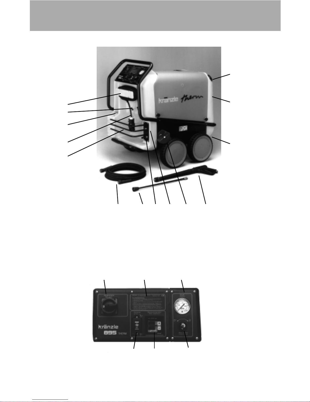
8 Storage bin for spray gun and pipe
9 Brake
10 Storage bin for accessories
11 Fuel tank
12 Filler aperture for fuel
13 High pressure outlet
14 Fuel drainage screw
1 Water inlet connection filter
2 Power cable
3 Winder for cable
4 Suction hose for detergent
5 High pressure hose
6 Spray gun
7 Spray pipe attachment
14 Master switch
15 Brief operating instructions
16 Heating switch
17 Thermostat
18 Manometer
19 Detergent dispensing valve
Page 4
4
The water flows into a tank. A float valve regulates the water intake. The water is
then directed to the safety spray pipe under pressure from the high pressure pump.
The high pressure spray is formed through this nozzle on the spray pipe.
The high pressure pump can draw a detergent/caring agent at the same time and
mix this with the spray.
Only open the dispensing valve when the chemical filter is immersed in
the liquid.
The user must follow the respective environmental, refuse and
water protection rules!
Description
Water and Detergent/Caring Agent System
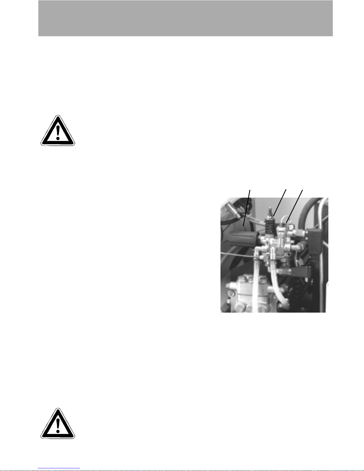
Pressure control and safety facilities
The pressure control valve allows full adjustment
of the quantity and pressure of the water.
The safety valve protects the machine from
excessive pressure and cannot be adjusted
beyond the admissible operating pressure. The
setting nuts are sealed with lacquer.
The flow controller switches off the oil burner if the
water level is too low, thus preventing the heating
chamber from overheating.
There is a temperature sensor in the chimney as
an additional precaution against the combustion
chamber overheating. This device switches the
combustion motor, the ignition transformer and
the magnetic valve off as soon as the exhaust
temperature rises above 250°C.
The unlocking button for the temperature cut-out
is located on the console at the combustion
chamber below the ignition transformer.
The system must be left for approx. 15 minutes before the unlocking button may be
pressed.
Call customer service if the temperature cut-out actuates repeatedly.
32
1
1 Handwheel for pressure
adjustment
2 Safety valve
3 Flow controller
Replacements, repairs, new adjustments and sealing operations
may only be performed by trained personnel.
Page 5

5
Brake
The Kränzle therm is fitted with a brake that prevents the machine from rolling away
on flat ground.
Always apply the brakes firmly when working with the machine !!!
Brakes applied
Brakes not applied
Motor protection switch
The pump motor is protected from overload by a motor protection switch. This
switch cuts out the motor in the event of overload. If the motor cuts out repeatedly,
locate and eliminate the cause of the fault.
Replacement and inspection work may only be performed by trained personnel.
Flame monitor
The system is fitted with a flame monitor.
The flame monitor prevents fuel being injected if combustion is not taking place.
There is a temperature sensor in the exhaust chimney of the combustion chamber,
and it is connected to the central electronic control circuit.
The burner is switched off if the temperature in the chimney has not reached 100°C
within 37 seconds of the burner being started, or if the exhaust gas temperature
drops below 100°C for longer than 2 seconds while the engine is in operation. The
magnetic fuel valve is cut-out. The message "FLA" for flame monitor is shown on the
display of the control panel.
Call customer service if the system cuts out repeatedly because of the flame
monitor.
Description
Page 6
6
Description
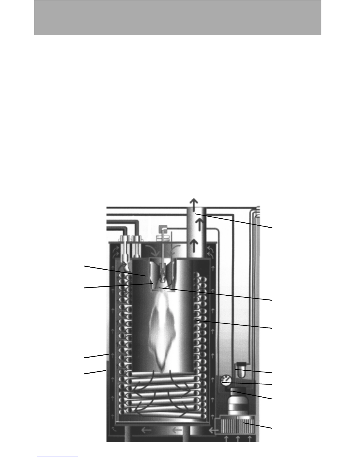
Heat exchanger
The heat exchanger is heated by a high pressure fan heater. A ventilator (1) draws in
the cold, fresh air from the bottom end of the machine and forces it upwards
between the outer mantle (2) and the inner mantle (3). In the process, the fresh air
is pre-heated and the inner and outer mantles are cooled. The pre-heated air is
pressed through a mixing unit (4). Here a finely atomised fuel is injected via a
nozzle (5) and mixed with the air. The electrodes (6) located below then ignite the
fuel-air mixture.
The flame burns from top to bottom, turns round and the hot gas flows past the
heating element (7) on its way back up. The burned gases collect in the exhaust
chamber and are emitted from the chimney(8).
The water is forced through a heating element by the high pressure pump. Hot air
flows around this, as described above.
The fuel pump (9) draws the oil through a filter (10) and pumps it to the injector
nozzle. The surplus quantity of fuel flows straight back into the tank. The oil
pressure is shown on the fuel manometer (11).
4
5
3
2
10
7
6
8
11
9
1
Page 7
7
Description
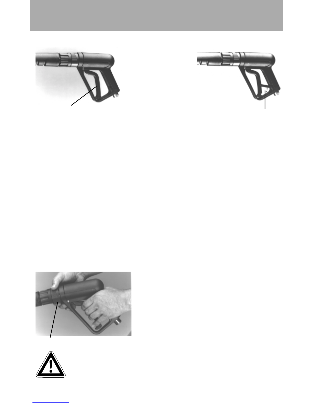
Spray pipe with spray gun
2
3
The spray gun only allows the machine to be operated when the safety trigger (no.
1) is pulled.
The spray gun can be used when the safety trigger is pulled. The liquid is then
pumped up to the nozzle. Spray pressure builds up and quickly reaches the
selected operating pressure.
When the trigger is released the gun is closed, which prevents any further liquid
from coming out of the spray pipe.
The recoil resulting from the gun being closed opens the pressure control valve in
the machine. The pump remains switched on and pumps the circuit with reduced
overpressure. When the gun is opened (trigger pressed) the pressure control valve
closes and the pump starts to operate again at the selected pressure.
If the gun is closed for longer than 20 seconds, the machine switches off. The pump
then restarts automatically when the gun is re-opened, provided the master switch
is on.
After completing work with your Kränzle therm , or if work is interrupted, the safety
catch (no. 2) must be applied. This makes it impossible to press the trigger by
accident.
The spray gun has bulit-in pressure regulation. If
the red ring on the handgrip (item 3) is turned to
the right the pressure reduces, and it increases
if turned to the left. But the manometer will still
indicate the pressure set on the control valve.
The spray gun is a safety device. Repairs
may only be performed by trained personnel. If spare parts are
required, use only those approved by the maker.
1
Page 8
Description
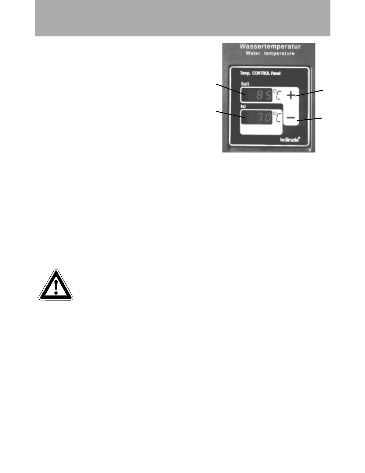
The thermostat controls the temperature of the
spray water. The target temperature is set using
two press-buttons (nos. 3 + 4) and can be read
from the top display (no. 1). If a button is held
down for longer, the target temperature setting
increases quickly in increments of 5°C.
The last temperature setting used remains
stored after the machine is switched off and
automatically becomes the default temperature
when the machine is switched back on.
The current spray temperature can be read from
the bottom display (no. 2).
When the machine is switched on, both displays show the figure "888" for approx 1
second to check the functioning of the units.
The thermostat also monitors the fuel level in the tank by means of a float switch. If
the fuel level falls below the minimum required quantity, the thermostat switches the
oil burner off and the word "OIL" blinks in the target temperature display window (no.
1). If the top display shows the letters "FLA" this indicates a malfunction in
combustion.
Thermostat
2
3
4
1
Safety information
IMPORTANT!
For safety reasons, the master switch must be put in the "0" position (ie,
the power must be switched off) after the washing process has been
completed.
At the start of the washing process the high pressure stream must be directed for at
least 30 seconds at the object being cleaned. It is possible for the water content
(approx. 5 l) of the combustion chamber to discolour during periods of disuse.
Description
The thermostat controls the temperature of the
spray water. The target temperature is set using
two press-buttons (nos. 3 + 4) and can be read
from the top display (no. 1). If a button is held
down for longer, the target temperature setting
increases quickly in increments of 5°C.
The last temperature setting used remains
stored after the machine is switched off and
automatically becomes the default temperature
when the machine is switched back on.
The current spray temperature can be read from
the bottom display (no. 2).
When the machine is switched on, both displays show the figure "888" for approx 1
second to check the functioning of the units.
The thermostat also monitors the fuel level in the tank by means of a float switch. If
the fuel level falls below the minimum required quantity, the thermostat switches the
oil burner off and the word "OIL" blinks in the target temperature display window (no.
1). If the top display shows the letters "FLA" this indicates a malfunction in
combustion.
Thermostat
2
3
4
1
Safety information
IMPORTANT!
For safety reasons, the master switch must be put in the "0" position (ie,
the power must be switched off) after the washing process has been
completed.
At the start of the washing process the high pressure stream must be directed for at
least 30 seconds at the object being cleaned. It is possible for the water content
(approx. 5 l) of the combustion chamber to discolour during periods of disuse.
8
Page 9

Safety Information
Safety Information
Important!!!
The machine must be disconnected from the power supply when
servicing work is being carried out. The master switch should be in
position "0" and the plug out of the socket.
The machine may only be used by persons who have received the necessary training.
* Never operate the machine without supervision.
* The water spray can be dangerous. It should never be directed at people, animals,
electrical apparatus or the machine itself.
* Never direct the spray at power sockets.
* Parts of the machine interior and parts of the gun and lance become hot when hot water
is used. Leave the cover of the machine closed when using the machine and do not
touch the metallic parts of the gun and lance.
* Children must not be allowed to use high pressure cleaning equipment.
* Do not damage the cable or repair it incorrectly.
* Do not pull the high pressure hose if there are kinks or loops in it. Make sure that the hose
is not damaged on sharp edges.
* Persons operating the machine should wear the necessary protective clothing, ie, water-
proof clothing, rubber boots, safety goggles, headwear etc.
* The high pressure spray can generate a high level of noise. If noise exceeds the maximum
allowed levels, users and others in the vicinity must wear suitable ear protection.
* The high pressure spray causes recoil and additional twisting movement if the gun is
angled. The gun must therefore be held firmly with both hands.
* Do not close off the exhaust aperture on the topside of the machine. Do not bend over this
aperture and do not put your hands inside it. Exhaust gases are very hot!
* Do not clamp down the trigger of the gun. Apply the safety catch after use, in order to
prevent accidental spraying.
* Do not spray against matter containing asbestos or other hazardous substances.
* Never spray liquids containing solvents, such as paint thinner, petrol, oil, or anythng
similar. Note the specifications of the additive makers! The seals in the machine are not
resistant to solvents. The spray vapour of solvents is highly inflammable, explosive and
poisonous.
* The machine may not be set up and used in rooms where there is a danger of fire or
explosion. The machine may not be used underwater.
* Air is required for combustion, and exhaust fumes are generated. If the machine is used
in closed rooms, make sure that the exhaust fumes can escape and that there is adequate
ventilation.
9
Page 10

10
Description
Electrical connection
The voltage given on the specification plate must match the mains voltage.
The machine is supplied with a power cable and plug.
The plug must be connected to a properly installed electrical socket with earthing and
have a 30 mA FI fault current safety switch. The socket must have a neutral 16A fuse on
the mains side.
If an extension cable is used, it must have an earth line that is properly
connected to the plug connections. The lines in the extension cable must
have a cross section of at least 1,5 mm². The plug connections must be of
spray protected design and may not lie on a wet surface. (If the extension
cable is longer than
10 m the minimum cross section is 2,5 mm²)
Important!
Extension cables that are too long cause a drop in the voltage and thus interruptions in
operation. If you are using a cable drum, the cable must always be fully unwound.
are also on the machine.
1. Connect the high pressure hose with the spray gun and lance to the machine.
2. Connect the water supply and turn on the tap.
3. Connect to the electrical supply.
4. Switch on the machine with the spray gun open and start the washing procedure.
5. When using the machine as a cold water high pressure cleaner:
ignition "OFF"
6. When using the machine as a hot water high pressure cleaner:
ignition "ON"
7. When using the machine as a hot water high pressure cleaner: preselect the water
temperature ("target" temperature) using the "+" und "-" buttons. The current water
temperature is shown in the "ACTUAL" display field.
8. A blinking "OIL" display on the temperature control panel indicates that there is
less than the minimum required quantity of heatng oil, and that the oil tank must be
refilled.
High pressure hose line and spray equipment
The high pressure hose line and spray equipment supplied with the machine are made
of high quality material specially adapted for the operating conditions of the machine, and
are properly marked.
Quick operating instructions
Page 11

11
If spare parts are required, only properly marked components approved by the
maker should be used. High pressure hoses and spray equipment must be
connected so that they are pressure-tight. The high pressure hoses should
not be driven over, pulled excessively or twisted. Do not pull the hose over
sharp edges, since this will invalidate the warranty.
* Secure the machine by applying the brake.
* Open the right cover of the machine (without chimney) and check
the oil level of the high pressure pump.
Do not start the machine if there is no oil in the sight glass.
Fill oil if necessary.
* Fill the fuel tank with light heating oil prior to use.
Use EL heating oil or diesel fuel only
Unsuitable fuels, such as petrol, may not be used (danger of explosion)
Water connection
Connect the machine to a water tap using a hose of at least 1/2" and turn on the
tap.
The water tank in the machine fills up. When the tank is full, the built-in float valve
closes the water inlet.
Use clean water only!
Follow the instructions of the local water supply utility.
Connection of the machine to drinking water mains must be in
accordance with DIN 1988.
Commissioning
High pressure connection
Connect the high pressure hose to the handgun.
Unwind the hose so that it is free of loops and connect it to the handgun and the
machine.
Check that all screw-type connections are pressure-tight.
Commissioning
Page 12

Commissioning
Check that the master switch is off (position "0").
Connect the power cable to a properly installed electrical socket with
earthing and a 30 mA FI fault current safety switch. The socket must have
neutral 16A fusing on the mains side.
Electrical connection
Switching on the machine
- Switch off the ignition.
- Set the pressure control valve to maximum pressure and close the detergent valve
- Open the gun and switch the master switch on.
The high pressure pump now presses the air out of the lines, and after a short time
the high pressure spray forms and the operating pressure is reached.
The machine is fitted with a Total-Stop-System. If the gun is closed for
longer than approx 20 seconds, the machine switches off automatically.
The machine restarts automatically when the gun is re-opened, provided
that the master switch is on..
Usage as a cold water high pressure cleaner
- Leave the ignition "OFF"
- Start cleaning
Usage as a hot water high pressure cleaner
- Set the target temperature on the thermostat using the "+" and "-" buttons.
- Switch the ignition "ON"
The oil burner starts to work. The water is heated up and kept
at the temperature you have set. The current water temperature
is shown in the "ACTUAL" display field.
- Wait until the pump has pressed the air out of the lines
- Put the chemical filter into a container of detergent
- Open the detergent valve.
The pump now draws detergent in and mixes it with the high pressure spray.
- Set the desired concentration of detergent.
Usage with detergents
12
Page 13

In the interests of the environment and to keep expenditure down, we
recommend sparing use of detergent. Please observe the
recommendations of the detergent manufacturer.
After using detergents, rinse the machine for approx 2 minutes by
pressing the trigger of the spray gun.
- There are two ways to adjust the working pressure:
1. Using the pressure control valve (see page 4) directly on the control and safetyblock
* Turn the handwheel (page 4; no. 1) to the left to decrease pressure.
* Turn the handwheel to the right to increase pressure.
2. Using the pressure control in the handgun (see page 7)
* Turn the red ring to the left to decrease pressure.
* Turn the red ring to the right to increase pressure.
Adjusting the pressure
Decommissioning
- Switch off the master switch (position "0")
- Pull the plug out of the power socket.
- Turn off the water supply.
- Open teh gun until the pressure is gone.
- Lock the gun
- Disconnect the water hose.
- Slacken the connections of the high pressure hose and gun and unscrew the high
pressure hose from the machine.
Decommissioning
Anti-Freeze Protection
The machine is normally still partially filled with water after work has been
completed. It is therefore necessary to take special precautions to protect the
machine from frost.
- Completely empty the machine of water.
Disconnect the machine from the water supply and switch off the ignition.
Switch on the master switch and open the gun. The pump now presses the
remaining water out of the heating element.
Do not allow the machine to run for longer than a miniute without water.
- Fill the machine with anti-freeze
If the machine is not in use for lengthy periods of time, it is advisable to
pump anti-freeze into the machine, especially in winter..
However, the best protection against frost is to keep the machine in a place that is
safe from frost.
13
Page 14
14
Care and Maintenance
Care and maintenance is required to keep the machine in good working order, and to
allow you to enjoy the machine for as long as possible..
IMPORTANT!!!
Always remove the plug before working on the machine!
What to do!
- weekly, or after approx 40 hours of operation
* Check the oil lebel on the housing of the high pressure pump
If the oil level is too low, top up with oil until the sight glass is full.
Change the oil if it has a grey or whitish appearance. The oil should be
disposed of responsibly.
* Check the filter in front of the float valve in the water tank and the fuel filter
in front of the magnetic valve. Clean the filters if necessary..
- Yearly, or after approx 500 hours of operation
* Desulphurise and clean the heating element.
* Check the oil burner and ignition system
Clean the oil nozzle, oil filter, magnetic valves and filter, clean and adjust
the ignition transformer, ignition cable and ignition electrodes and replace
defective parts
Care and Maintenance
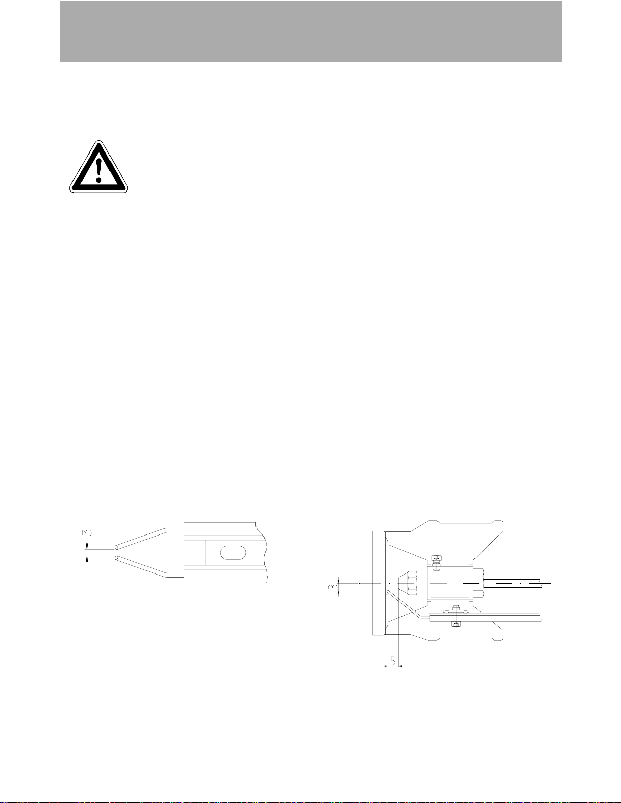
Adjusting ignition electrodes
Page 15
15
Care and Maintenance
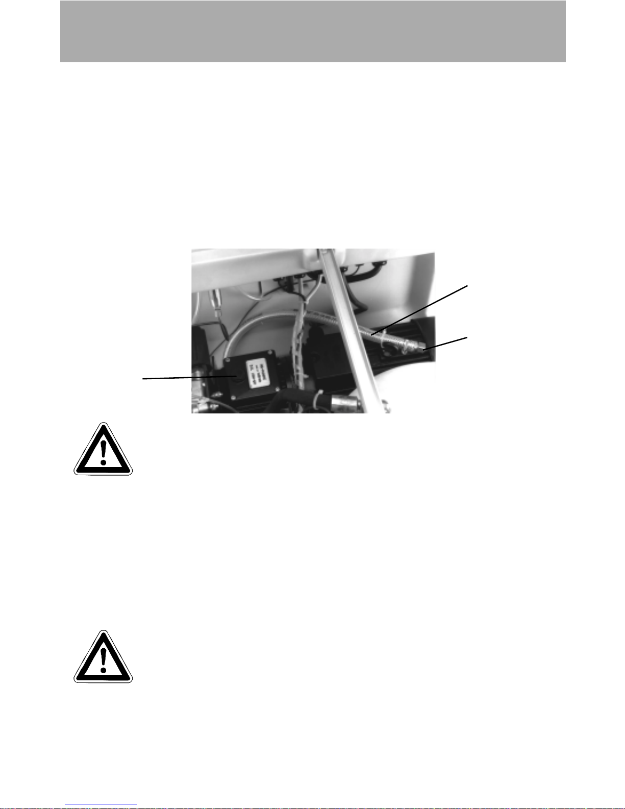
Changing the oil
The oil of your high pressure pump should be changed after approx 40 hours of
operation or if it has a grey or whitish appearance..
To do this, take the oil drainage hose (1) from the inside of the machine and open
the oil filler cap (2) on the top side of the oil reservoir. Open the bung (3) at the end
of the hose. Drain off teh oil and dispose of it responsibly. Close the end of the
hose.
Refill with oil until the sight glass is full.
Type of oil: Formula RS (Castrol) or semi-synthetic motor oil
Quantity: 1,0 l
3
2
1
Fuel System
Your fuel may contain particles of dirt, or impurities may get into the tank during
refuelling. Check the tank for impurities on a regular basis. Clean the tank when
necessary
Empty the fuel tank using the drainage screw at the bottom of the tank. Clean the
tank and fuel lines.
Replace the drainage screw.
Detergent and dirty fuel must be disposed of responsibly.
Page 16

Care and Maintenance
Decalcifying the heating element
Calcified machines use an unnecessary amount of energy because the water can
only be heated slowly and the excess pressure valve feeds a part of the water back
into the pump.
Calcified machines can be recognised by increased pipeline resistance.
Check pipeline resistance by disconnecting the high pressure lance from the gun
and switching the machine on. A full jet of spray emerges from the gun. The
machine must be decalcified if the pressure shown on the manometer is greater
than 25 bar.
CAUTION!!!
Decalcifiers are caustic!
Observe the instructions for usage and accident prevention. Wear
protective clothing to prevent the decalcifying agent from
contacting your skin, eyes and clothing (eg, gloves, safety mask
etc.)
Proceed as follows to decalcify the machine:
* Unscrew the high pressure hose from the machine and decalcify these separately
* Put the detergent suction hose into a container of decalcifying solution.
* Set the dispenser valve to the maximum concentration.
* Switch on the machine.
* Hold the gun in a separate container and press the trigger.
* Wait for about a minute until the decalcifier comes out of the gun
(recognisable by its whitish colour)
* Switch off the machine and allow the solution to act for about 15-20 minutes.
* Switch the machine back on and rinse it through with clear water for about 2
minutes.
Now check whether pipeline resistance is back to an acceptable level. Repeat the
decalcifying process if the pressure without the high pressure lance is still above 25
bar.
16
Page 17

Inspections
Rules, directives, inspections
* Inspections performed by Kränzle
- measurement of earth line resistance
- measurement of voltage and current
- inspection of tension consistency with +/- 1530 V
- pressure check of heating element at 300 bar
- visual and functional check as per the inspection sheet provided
- exhaust fukme analysis(see test strips provided)
* Guidelines for liquid sprayers
The machine conforms with the "Guidelines for liquid sprayers"). These guidelines
are issued by the organisation of trade associations and may be obtained from
Carl Heymann-Verlag KG, Luxemburger Str. 49, 50939 Köln.
These guidelines specify that this machine is to be inspected by qualified
personnel whenever necessary, but no less than once every 12 months.
These inspections must be recorded in the inspection log at the end of this
manual.
* Pressure container and steam boiler directives
Kränzle high pressure cleaning equipment conforms to the pressure container
and steam boiler directive. No construction approval, notification of licence and
takeover inspection are required. The water capacity is less than 10l.
* Duties of owner
The owner is to ensure before the sprayer is used that all safety-relevant
components are in a serviceable condition. (Eg, safety block, hose and electric
cables, spray equipment etc).
* Emission control legislation
With stationary installation, the emission levels of the machine must be checked
once a year by a qualified organisation or person according to German law.
The first inspection must be carried out four weeks after the machine is
commissioned. The owner is responsible for having the inspection performed.
17
Page 18

Troubleshooting
Troubleshooting
IMPORTANT!!!
Always remove the plug before working on the machine!
Multi-function thermostat
The thermostat has several functions.
Display Possible cause Action
"Err OFF" Temperature of over
170° at the sensor
The burner does not switch off properly. Check thermostat,
thermocouple and klixon and renew if necessary
"Err 2" Sensor broken Check that the sensor plug (2-pole plug on back of
thermostat) is properly engaged and contacted.Follow the
sensor cable to the end.
"OIL" Fuel tank empty Refill EL heating oil
"FLA" Combustion defect 1) check fuel filter, clean if necessary
2) check ignition electrode and burner setting and adjust or
replace if necessary
3) check fuel pump and magnetic valve
4) Check the ignition transformer
"E 1" Memory error. Target
value can be set but
not saved
Replace thermostat at the next opportunity and send in for
repair. Target value must be reset each time the machine is
switched on.
"E 4"
"E 5"
Memory loss Replace thermostat and send in for repair
"888" not
displayed
when
machine is
switched
on
Defective display unit Replace thermostat and send in for repair
18
Page 19

Troubleshooting
Malfunctions without display
Malfunction Possible cause Action
Machine fails to start No electrical voltage at
machine
Master switch defective
Motor protection switch
actuated
Press switch (S3 or S5)
defective
Motor protection (K3) switch
defective
Check power supply and cables
Check and replace if necessary
Eliminate cause of overload
Check and replace if necessary
Check and replace if necessary
High pressure pump runs but
burner fails to ignite
Set water temperature
reached
Pre-ventilation time not yet
elapsed
Ignition switched off
Fuel tank empty, "OIL"
display at thermostat
Thermostat defective
Ignition switch defective
Float switch in fuel tank
defective
Fuel filter dirty
Fuel nozzle defective
Flow controller (S2) has
switched off
Contact of flow controller
defective or incorrectly set
Ignition contacts incorrectly
set or burned out
Increase target water
temperature, open gun with
machine on until water
temperature drops
Hold gun open for approx 5
seconds
Ignition switch "ON"
Refill fuel
Check and replace if necessary
Check and replace if necessary
Check and replace if necessary
Check and clean if necessary
Check and replace if necessary
Check water inflow; clean filter in
water tank
Readjust, check, replace
Readjust, check, replace
19
Page 20

20
Troubleshooting
Diagnosis using light diodes on control panel
The location of the diodes on the control panel is shown on page 27.
Malfunction Possible cause Action
High pressure pump
operates but burner fails to
ignite
Ignition cable defective
Ignition transformer defective
Burner motor (M2) defective
Coupling between burner motor
and fuel pump defective
Fuel pump defective
Fuel magnetic valve (Y1) dirty or
defective
Press switch (S3) or (S5)
defective
Contactor (K3) defective
Check and replace if necessary
Check and replace if necessary
Check and replace if necessary
Check and replace if necessary
Check and replace if necessary
Clean, check, replace if
necessary
Check and replace if necessary
Check and replace if necessary
IMPORTANT!
The system must be
connected to the power
mains when the LEDs
are checked.
You must therefore be
as careful as possible.
Disconnect the system
from the power mains
as soon as possible
afterwards.
Remove the plug from
the socket!
Diode Illuminates when
Diode D7 must light up directly after the system is
switched on, otherwise check fuses F1 and F2 on the
circuit board.
D7 Motor start-up allowed
- heating element press switch (S5) in
rest position or re-run delay active
D11 Excess temperature not exceeded
- Klixon (S1) not actuated
D12 Magnetic valve release illuminates 3.5 seconds after D17
D16 Motor start-up allowed
- heating element press switch (S5) in rest position
D17 Burner start-up allowed
- Thermostat (B1), flow controller (S2)
and pump press switch have actuated
D18 Low oil level
- float switch oil control (S4) closed
D20 In case of sensor breakage refer to Flame Monitor
Sensor.
Page 21

21
A1 Ignition transformer S2 Flow controller
B1 Thermostat S3 Pump press switch (ND)
F1 Excess current actuator S4 Float switch (fuel)
K3 Motor contactor S5 Hose press switch (HD)
M1 3-phase AC motor, HP pump S10 Thermosensor
M2 Burner motor X1 5-pole socket panel
Q1 Master switch X2 6-pol socket panel
Q2 Heating switch Y1 Fuel valve
Glow
lamp
Anti-
interference
device
Inlet line via
CEE 5x 16 A
380 V 50 Hz +MP
Thermostat
B1
Measuring
sensor
Control plate
Q2
Switch for
activating
burner
3x 400V / 50Hz
Circuit diagramme
Flame Monitor
Sensor
Page 22

22
Terminal box terminal plan
3x 400V / 50Hz
Terminal box
Ignition
transformer
Magnetic
valve (fuel)
Burner motor
Flow
controller
Float switch
(fuel)
4-pole connection line
heating
4-pole control line,
sensors
Pump press
switch (ND)
Hose press
switch (HD)
Page 23

223232323
23
Cockpit terminal plan
Page 24

24
A1 Ignition transformer S2 Flow controller
B1 Thermostat S3 Pump press switch (ND)
F1 Excess current actuator S4 Float switch (fuel)
K3 Motor contactor S5 Hose press switch (HD)
M1 3-phase AC motor, HP pump S10 Thermosensor
M2 Burner motor X1 5-pole socket panel
Q1 Master switch X2 6-pol socket panel
Q2 Heating switch Y1 Fuel valve
Antiinterference
device
Inlet line via
CEE 5x 16 A
380 V 50 Hz +MP
Control plate
Q2
Switch with
Glowlamp for
activating burner
3x 220V / 60Hz
Circuit diagramme
Thermostat
B1
Measuring
sensor
Flame Monitor
Sensor
Page 25

52524
25
Terminal box
Ignition
transformer
Magnetic
valve (fuel)
Burner motor
Flow
controller
Float switch
(fuel)
4-pole connection line
heating
4-pole control line,
sensors
Pump press
switch (ND)
Hose press
switch (HD)
Terminal box terminal plan
3x 220V / 60Hz
Page 26

Flame Monitor
Sensor
Hauptschalter
B1 Thermostat
Mains connection
cable
4-pole control
line, sensors
4-pole connection
line, heating
3-phase AC motor
High pressure
pump
Earth cable
equipment frame
Control plate
Motor
contactor
Heating switch
Excess current
actuator
Cockpit terminal plan
3x 220V / 60Hz
Thermosensor
Thermostat
26
Page 27

27
Pipeline plan
Control panel with light diodes
High pressure
connection
Control and
safety block
RSB 250
1 Float valve, water inlet 8 Press switch, hose
2 Water tank 9 Safety valve
3 Control valve, detergent 10 Excess pressure line, safety valve
4 High pressure pump 11 Flow controller
5 Press switch pump (ND) 12 Fuel pump with magnetic valve
6 Unloader valve 13 Fuel filter
7 By-pass line, unloader 14 Fuel tank
Heating chamber
Detergent
D11
D12
D7
D16
D17D18
D20
F1
F2
F1: T32 mA Best.Nr.: 44.200 1 F2: M 250 mA Best.Nr.: 44.200 2
Page 28

28
Complete assembly
Page 29

29
29999999999999999999999999999999999999999999999999999999999999999999999999999999999999999999999
29
Kränzle therm 895 / 1165
Pos. Description Qty Order No.
1 Cockpit 1 44.006
2 Brennstofftank 1 44.004
3 Wassertank 1 44.009
4 Kabelaufwicklung 1 44.007
5 Lanzenköcher 1 44.008
6 Haube rechts 1 44.032
7 Haube links 1 44.031
8 Rad 4 44.017
9 Radkappe 4 44.018
10 Bremspedal 1 44.022
11 Bremshebel 1 44.023
12 Bremsklotz 1 44.024
13 Tankdeckel 1 44.005
14 Fahrgestell 1 44.001
15 Frontbügel 1 44.002
16 Schubbügel 1 44.003
17 Reeling 1 44.016
18 Top-Strebe 1 44.019
19 Starlock-kappe 20 mm 4 40.142
20 O-Ring 70 x 5 1 44.020
21 Innensechskantschraube M 8 x 12 4 40.122
22 Innensechskantschraube M 8 x 40 2 44.033
23 Unterlegschiebe 8,4 DIN 9021 4 41.409
24 Schraube 3,9 x 16 4 12.150
25 Stift 6 x 50 1 44.035
26 Starlockkappe 8 mm 1 44.165
27 Schloßschraube M 8 x 35 2 41.408
29 Stift 6 x 40 1 44.035 1
30 Elastic-Stop-Mutter M 8 2 41.410
32 Kunststoffschraube 6 x 30 4 43.423
33 Kunststoffschraube 5 x 25 8 41.414
35 Scheibe 4 44.034
36 Sterngriff 4 50.168 1
37 Hochdruckschlauch NW 8 20 m 1 41.083
38 O-Ring 9,3 x 2,4 Viton 2 13.273 1
39 Pistole mit Verlängerung - Starlett II 1 41 053 1
40 Lanze mit Flachstrahldüse 25045 (für therm 895) 1 12.392
40.1 Lanze mit Flachstrahldüse 2507 (für therm 1165) 1 12.392 1
Page 30

30
Switchbox electronics
Page 31

31
Kränzle therm 895 / 1165
Pos. Description Qty Order No.
1 Frontplatte Elektrik 895 1 44.042
1.1 Frontplatte Elektrik 1165 1 44.042 2
2 Frontplatte Manometer 1 44.043
3 Gummidichtung Elektrik 1 44.044
4 Kabeldurchführungsplatte 1 44.045
5 Hauptschalter KG32B T203/01E 1 44.046
6 Dichtung für Thermostat 1 44.101 1
7 Klemme Wago 2,5 mm² 1 44.047
8 Manometer 1 15.039 1
9 Klemmbügel für Manometer 1 44.049
10 Steuerplatine für 3x 400V / 50/60Hz 1 44.196
10.1 Steuerplatine für 3x 220V / 50/60Hz 1 44.196 1
11 Erdungsklemme Wago 2,5 mm² 1 44.048
12 Thermostat 1 44.101
14 Gehäuse Waschmittelventil 1 44.145
15 O-Ring 5 x 1,5 (Viton) 1 44.150
16 Heizungsschalter 1 41.111 6
17 Elastic-Stop Mutter M 4 4 41.111
18 Klemmrahmen mit Schalterabdichtung 1 41.110 5
19 Kunststoffschraube 3,5 x 9,5 2 41.088
20 Schraube M 5 x 14 10 40.536
21 Kunststoffschraube 5,0 x 14 6 43.426
22 PG-Verschraubung PG 11 3 41.419
23 PG-Verschraubung PG 9 1 41.087
24 PG-Verschraubung PG 16 2 41.419 1
25 O-Ring 28,24 x 2,62 1 44.149
26 Schlauchklemme 9 - 9 2 44.054
27 Kunststoffschlauch für Waschmittelansaugung 1 44.055
28 Kunststoffschlauch mit Filter 1 44.056
29 Motorschütz CA3-12-10 für 3x 400V / 50/60Hz 1 44.057
29.1 Motorschütz CA3-23-10 für 3x 230V / 50/60Hz 1 44.057 2
30 Thermorelais CT3-12 8,5 - 12,5 A 1 44.058
30.1 Thermorelais CT3-23 16 - 23 A 1 44.058 3
31 Hutschiene 50 mm lang 2 44.125 1
32 Hutschiene 30 mm lang 1 44.125 2
33 Blechschraube 3,9 x 9,5 16 41.636
34 Verschlußdeckel für Durchgangsklemme 1 44.047 2
35 Kabelhaltesockel 5 44.135
36 Anschlußmuffe Manometer 1 44.136
37 Druckmeßleitung 1 44.102
38 Blechschraube 3,5 x 19 2 44.162
39 Blechschraube 3,5 x 16 3 44.161
40 Drehgriff Chemieventil mit Blendkappe 1 44.151
41 Regulierkolben Chemieventil 1 44.147
42 Edelstahlfeder 1,8 x 15 x 15 1 44.148
43 Deckel für Chemieventil 1 44.146
Chemieventil kpl. Pos. 14; 15; 25-27; 39-43 44.052
F1 Feinsicherung T 32 mA 1 44.200 1
F2 Feinsicherung M 250 mA 1 44.200 2
Page 32

32
Water supply
Water supply
Pos. Description Qty Order No.
1 Wassertank 1 44.009
2 Schwimmerventil 1 44.025
4 Distanzring 1 44.026
5 Anschlußstück R 3/8" IG 1 41.423
7 Einströmschlauch 1 44.027
9 O-Ring 13 x 2,6 2 13.272
10 Schlauchtülle 2 44.126
11 Überwurfmutter 2 41.047
12 Schlauchschelle 12 - 22 3 44.054 2
13 Wassereingangsschlauch 1 44.028
14 Schlauchtülle R3/8" x 13 1 44.029
16 Ermetorohr 12 mm 1 44.030
17 Ermetomutter 12 mm 2 40.075
18 Klemmhülse 12 mm 2 40.074
19 Ermetoverschraubung 12 L x 12 L 1 44.060
20 Wasserausgangsteil 1 44.061
21 O-Ring 1 41.047 3
22 Steckkupplung 1 41.047 2
23 Gummidichtung 1 41.047 1
24 Wasserfilter 1 41.046 2
Steckkupplung kpl. Pos. 21-23 41.047 4
Page 33

3333
33
Fuel supply
Pos. Description Qty Order No.
1 Deckel Brennstoffversorgung 1 44.011
2 Flansch mit Brennstoffleitungen 1 44.010
3 Gummidichtung 1 44.012
5 Schwimmerschalter 1 44.014
8 Rücklaufschlauch 1 44.015
9 Schlauchschelle 7 - 11 2 44.054
10 Einschraubwinkelverschraubung 1/4" x 6 1 44.062
11 Kunststoffschraube 4,8 x 25 3 41.414
15 Kugelhahn 1 44.203
16 Anschlußteil Brennstofffilter 2 44.214
17 Gummidichtung 3/4" 2 41.047 1
18 Filtergrundkörper 1 13.301
19 Gummidichtung 1 13.303
20 Siebkörper Brennstofffilter 1 44.213
21 Filterbecher 1 13.302
22 Einschraubwinkel R1/4" AG x 10L 2 40.121 1
23 Brennstoffpumpe mit Magnetventil 1 44.073
24 Brennstoffmanometer 0-15 bar R1/8" 1 44.082
25 Magnet für Magnetventil 1 44.111 1
26 Anschlußkabel für Magnetventil 1 44.111
27 Abstandsrohr 128 mm 1 44.084
28 Schlauchtülle 1/4" x 6 1 44.053
29 Winkeleinschraubverschraubung 1/8" x 6 1 44.110 1
Page 34

34
Heat exchanger
Page 35

35
Kränzle therm 895 / 1165
Pos. Description Qty Order No.
1 Außenmantel 1 44.063
2 Heizschlange mit Innenmantel 1 44.064
3 Hydrospeicher 1 44.140
4 Innendeckel 1 44.065
5 Außendeckel 1 44.066
6 Anschlußmuffe für Hydrospeicher 1 44.140 1
7 Gebläsestutzen 1 44.068
8 Gebläsegehäuse 1 44.069
9 Gebläsedeckel 1 44.070 1
10 Lüfterrad 1 44.071
11 Brennermotor 220 V / 50 Hz 1 44.072
12 Brennstoffpumpe mit Magnetventil 1 44.073
14 Einstellbare T-Verschraubung 12 1 44.141
16 Winkelverschraubung 6L x 6L 1 44.106
17 Düsenstock 1 44.076 4
18 Brennstoffdüse 60° B 1,5 gph bei 895 1 44.077
18.1 Brennstoffdüse 60° B 1,75 gph bei 1165 1 44.077 4
19 Düsenhalter 1 44.078
20 Deckel Düsenstock 1 44.079
21 Blockelektrode 1 44.080
22 Brennstoffleitung Pumpe 1 44.108
23 Abschlußhülse 2 44.081
24 Brennstoffmanometer 0 - 15 bar R 1/8" 1 44.082
29 Steckkupplung 1 44.085
30 Abschlußring 2 44.086
31 Tiefenanschlag 1 44.088
33 Brennstoffleitung „Düsenstock“ 137 mm 1 44.089
34 Scheibe 8,4 DIN125 7 50.186
35 Mutter M 8 7 14.127
36 Ringmutter M 8 DIN 582 3 44.115
38 Gewindestift M 6 x 8 DIN 914 7 44.090
39 Klemmblech für Elektrode 1 44.076 1
40 Zyl.schraube mit ISK M 5 x 15 DIN6912 1 44.076 2
44 Zyl.schraube mit ISK M 5 x 12 DIN 912 1 40.134
45 Schraube M 6 x 12 3 43.421
46 Kunststoffschraube 5,0 x 20 9 50.157
47 Blechschraube 4,8 x 13 4 44.112
48 Schraube M 4 x 10 4 44.091
49 Unterlegscheibe 4,3 4 44.059
52 Blechschraube 6,3 x 13 7 44.109
54 Einschraubwinkelverschr. 3/8" x 12L 2 44.092
55 Hochdruckschlauch 1 44.093
57 Schneidring 12 mm 1 40.074
58 Winkeleinschraubverschraubung 1/8" x 6 1 44.110 1
59 Überwurfmutter f. Ermeto 12 mm 1 40.075
60 Ermetorohr 1 44.030
62 Unterlegscheibe A 10,5 DIN 9021 3 50.182
63 Sechskantschraube M 10 x 20 DIN 933 3 44.116
64 Federring A 10 DIN 127 3 44.116 1
68 Fühler Muffe 1 44.171
69 Mutter 2 44.172
70 Thermofühler für Flammüberwachung 1 44.199 1
71 Klemmring für Meßleitung Thermostat 1 44.087 1
72 Meßleitung Thermostat 1 44.101 2
Page 36

36
Pos. Description Qty Order No.
1 Ventilgehäuse Sicherheitsblock 1 40.590
2 Verschlußschraube R 1/8" IG 1 40.591
3 Dichtstopfen M 8 x 1 3 13.158
4 Dichtstopfen M 10 x 1 1 43.043
5 O-Ring 15 x 2 5 13.150
6 Kolbenführung spezial 1 42.105
7 Stömungskörper 1 40.592
8 O-Ring 11 x 1,44 4 12.256
9 Edelstahlsitz 8,2 mm 2 13.146
9.1 Edelstahlsitz 7,0 mm 1 14.118
10 Sprengring 2 13.147
11 Edelstahlkugel 10,0 mm 3 12.122
12 Edelstahlfeder 2 14.119
13 Verschlußschraube 1 14.113
14 Steuerkolben Sicherheitsventil 1 14.110
15 Parbaks 16 mm 2 13.159
16 Parbaks 8 mm 2 14.123
17 Spannstift 2 14.148
18 Kolbenführung 1 14.109
19 Sechskantmutter M 8 x 1 2 14.144
20 Ventilfeder 2 14.125
21 Federdruckscheibe 2 14.126
22 Nadellager 1 14.146
23 Handrad 1 14.147
24 Steuerkolben 1 14.134
25 Elasic-Stop-Mutter 1 14.152
26 Rückschlagfeder „K“ 1 14.120 1
27 Klemmstück 1 40.593
28 Schraube M 4 x 10 2 41.489
29 Magnetschalter 1 40.594
30 Sechkantmutter M 8 2 14.127
31 Eingangsstück R 3/8" 1 13.136
32 Verschlußschraube M 14 x 1 1 40.595
Control and safety block
Page 37

37
Pos. Description Qty Order No.
1 Konsole mit integr. Klemmkasten 1 44.067 1
2 Transformator 230 V / 50 Hz 1 44.074
3 Kunststoffschraube 4,0 x 25 8 43.425
4 Deckel für Klemmkasten 1 44.075 2
6 Hutschiene für Verteilerkasten 1 44.125
7 Durchgangsklemme grau 18 44.047
8 Durchgangsklemme grün/gelb 3 44.048
9 Querbrücker 24 A 6 44.047 1
10 Entstörkondensator 1 44.124
11 Blechschraube 3,9 x 9,5 7 12.172
14 Kunststoffschraube 4 x 60 4 43.420
18 Zündkabel mit Stecker 1 44.114
19 PG-Verschraubung PG 16 2 41.419 1
20 PG-Verschraubung PG 11 5 41.419
22 Haltesockel für Entstörglied 1 44.178
23 Abdeckplatte für Durchgangsklemme 1 44.047 2
24 Abdeckplatte für Sicherungsklemme 1 44.166 1
25 Halteklemme für Feinsicherung 1 44.166
25.1 Feinsicherung 3,15 A träge 1 44.166 3
26 Abdeckkappe Überstromauslöser 1 44.154
27 Schraube M 4 x 12 2 41.089 1
28 Dichtung für Übertemperaturauslöser 1 44.157
29 Übertemperaturauslöser 2 44.169
30 Deckel für Übertemperaturauslöser 2 44.182
31 Dichtung für Deckel Übertemperaturauslöser 1 44.182 1
32 Dichtung für Deckel Klemmkasten 1 44.075 3
Terminal box and transformer
Page 38

38
Connections
Page 39

39
Pos. Description Qty Order No.
1 Aggregathalterung 1 44.013
2 Halteblech Sicherheitsblock 1 44.095
3 Innensechskantschraube M 12 x 45 4 40.504
4 Elastic-Stop-Mutter M8 4 41.410
5 Unterlegscheibe 8,4 DIN 9021 7 41.409
6 Innensechskantschraube M 8 x 30 3 41.036 1
7 Schlauchschelle 7 - 10 1 44.054
8 Schlauchtülle 3/8" x 6 1 44.029
9 Schlauchtülle 1/4" x 6 3 44.053
10 Schlauchschelle 10-16 3 41.046 3
11 Waschmittelsaugschlauch 1 44.055
12 Verschlußschraube 1/2" AG mit 1/4" IG 1 44.121
13 Einschraubwinkel R1/4" IG/AG 4 40.121
14 O-Ring 13 x 2,6 1 13.272
15 Druckschalter (schwarz) kpl. mit Kabel 0,59 m 1 44.120
15.1 Druckschalter (rot) kpl. mit Kabel 0,49 m 1 44.120 1
16 By-Pass- Verbindungsschlauch 1 44.097
17 Schwingmetall 30 x 30 4 44.227
18 Klemmhülse 12 mm 2 40.074
19 Ermetomutter 12 mm 2 40.075
20 Einschraubwinkelverschraubung 3/8" x 12 3 44.092
21 Ermetorohr Pumpenausgang 1 44.098
22 Elastic-Stop-Mutter M 6 3 14.152 1
25 Hochdruckschlauch 1 44.093
26 Innensechskantschraube M 6 x 30 2 43.037
27 Sauganschluß 3/8" AG x 3/4" AG 1 41.016
28 Schlauchtülle für Sauganschluß 1 44.126 1
29 Druckmessleitung 1 44.102
30 Einschraubverschr. 1/8" x 6 mm 1 40.591 1
31 Bypass Schlauch Sicherheitsventil 1 44.104
33 Schlauchverschraubung 3/4" x 19 1 44.122
34 Schlauchschelle 20 - 32 2 44.054 1
35 Gummidämpfer 2 43.419
36 Ansaugschlauch 1 44.096
37 Saugglocke mit Sieb 1 15.038 5
Kränzle therm 895 / 1165
Page 40

40
Transmission unit
Page 41

41
Kränzle therm 895 / 1165
Pos. Description Qty Order No.
1 Ölgehäuse 1 40.501
4 Innensechskantschraube M 8 x 25 6 40.053
5 Sicherungsscheibe 6 40.054
6 Flachdichtung 1 40.511
7 Öldichtung 20 x 38 x 7 3 40.044 1
8 Wellenscheibe 1 40.043
9 Axial-Rollenkäfig 1 40.040
10 AS-Scheibe 1 40.041
11 Taumelscheibe 9,5° bei 895 400V / 50Hz 1 40.042 1-9,5
11.1 Taumelscheibe 12,0° bei 1165 400V / 50Hz 1 40.042 1-12,0
11.2 Taumelscheibe 8° bei 895 3x 220V / 60Hz 1 40.042 1-8,0
11.3 Taumelscheibe 10,4° bei 1165 3x 220V/60Hz 1 40.042 1-10,4
12 Plungerfeder 3 40.506
13 Federdruckscheibe 3 40.510
14 Plunger 20 mm (lang) 3 40.505
15 Sprengring 3 40.048
16 O-Ring 14 x 2 2 43.445
17 Verschlußschraube M 18 x 1,5 1 41.011
18 Flachdichtung 1 41.019 3
19 Deckel 1 40.518
20 Innensechskantschraube M 5 x 12 4 41.019 4
21 Ölmeßstab 1 42.520
22 Stützscheibe für Plungerfeder 3 40.513
23 Einschraubwinkel 3/8" x 3/8" 1 44.127
24 Ölablasschlauch 1 44.128 1
25 Kupferring 3 14.149
26 Verschlußkappe 1 44.130
Page 42

42
Valve housing
Pos. Description Qty Order No.
1 Ventilgehäuse 1 40.502 1
2 O-Ring 18 x 2 6 40.016
3 Einlaß- / Auslaß- Ventil 6 42.024
4 O-Ring 21 x 2 6 42.025
5 Ventilstopfen 6 42.026
6 Sicherungsring 4 40.032
7 Innensechskantschraube M 12 x 45 4 40.504
13 Gewebemanschette 3 40.023
14 Backring 20 mm 6 40.025
15 O-Ring 31,42 x 2,62 3 40.508 1
16 Leckagering 20 x 36 x 13,3 3 40.509
17 Cu-Dichtring 21 x 28 x 1,5 1 42.039
18 Gummimanschette 3 40.512
19 Verschlußschraube R 1/2" 1 42.032
20 Distanzring mit Abstützung 3 40.507
21 Cu-Dichtring 17 x 22 x 1,5 1 40.019
22 Verschlußschraube R 3/8" 1 40.018
23 Druckring 20 mm 3 40.021
24 Zwischenring 3 40.516
Reparatur - Satz Manschetten und Messingteile
40.065 1
bestehend aus: 3x Pos. 13; 6x Pos. 14; 3x Pos. 15;
3x Pos. 16; 3x Pos. 18; 3x Pos. 20; 3x Pos. 23
Reparatur - Satz Manschetten 40.517
bestehend aus: 3x Pos. 13; 6x Pos. 14; 3x Pos. 15;
3x Pos. 18; 3x Pos. 23
Page 43

Kränzle therm 895 / 1165
Motor
Pos. Description Qty Order No.
1 Stator 112 5,5 kW 400V / 50Hz 1 40.540
1.1 Stator 112 3x 220V / 60 Hz 1 40.541
2 A-Lager Flansch 1 40.530
3 Rotor 112 1 40.531
4 Lüfterrad BG112 1 40.532
5 Lüfterhaube BG 112 1 40.533
6 Klemmkasten 1 40.534
7 Flachdichtung 1 43.030
8 Lüsterklemme 2,5 mm² 4-polig 1 43.031 1
9 PG-Verschraubung PG 13,5 1 40.539
10 Kegelrollenlager 31306 1 40.103
11 Öldichtung 35 x 47 x 7 1 40.080
12 Paßfeder 8 x 7 x 32 1 40.104
13 Kugellager 6206 - 2Z 1 40.538
14 Innensechskantschraube M 6 x 30 4 43.037
16 Blechschraube 2,9 x 16 1 43.036
17 Vierkantmutter M 5 2 41.416
18 Schraube M 5 x 14 2 40.536
19 Schraube M 4 x 12 4 41.489
20 Schelle für Lüfterrad BG112 2 40.535
21 Schraube M 4 x 12 4 41.489
22 Erdungsschraube kpl. 1 43.038
43
Page 44

44
Kränzle therm 895 / 1165
Pressure switch
Pos. Description Qty Order No.
1 Gehäuse (schwarz) 1 15.007
1.1 Gehäuse (rot) 1 15.007 1
2 Deckel (schwarz) 1 15.008
2.1 Deckel (rot) 1 15.008 1
3 Gehäuse Steuerkolben 1 15.009
4 Steuerkolben 1 15.010
5 Ausgangsteil R 1/4" AG 1 15.011
6 Parbaks 7 mm 1 15.013
7 O-Ring 5 x 1,5 1 15.014
8 Scheibe 1 15.015
9 Edelstahlfeder 1 15.016
10 O-Ring 12,3 x 2,4 1 15.017
11 Mikroschalter 1 15.018
12 Anschlußkabel 0,59 m 1 44.131
12.1 Anschlußkabel 0,49 m 1 44.131 1
13 Gummimanschette für PG 9 1 15.020
14 Scheibe für PG 9 1 15.021
15 Druckschraube PG 9 1 15.022
16 O-Ring 44 x 2,5 1 15.023
17 Blechschraube 2,8 x 16 6 15.024
18 Schraube M 4 x 20 2 15.025
19 Mutter M 4 2 15.026
Page 45

45
Gun
Pos. Description Qty Order No.
1 Ventilkörper mit Handgriff 1 12.294
2 Schutzhülse 1 12.295
3 Abdeckschutz 1 12.296
4 Betätigungshebel 1 12.298
5 Sicherungshebel 1 12.149
6 Abschlußschraube M 16 x1 1 12.247
7 Stopfen 1 12.287
8 Gewindeführungshülse R 1/4" AG 1 12.250
9 Aufsteuerbolzen 1 12.284
10 Stift 1 12.148
11 Lagernadel 1 12.253
12 Edelstahlfeder 1 12.246
13 Edelstahlkugel 1 12.245
14 Edelstahlsitz 1 13.146
15 O-Ring 11 x 1,44 1 12.256
16 O-Ring 3,3 x 2,4 1 12.136
17 Blechschraube 3,9 x 8 4 12.297
18 Druckstück 1 12.252
19 Rohr kunststoffumspritzt bds. R 1/4" AG 1 15.004 5
20 Überwurfmutter ST 30 M22 x 1,5 IG 1 13.276 1
21 Außen-Sechskant-Nippel R 1/4" IG 1 13.277 1
22 O-Ring 9,3 x 2,4 1 13.273
23 Aluminium-Dichtring 4 13.275
24 O-Ring 15 x 1,5 1 12.129 1
25 Sicherungsring 1 12.258
51 Düsenschutz 1 26.002
52 Rohr 500 mm; bds. R1/4" 1 12.385 1
53 ST 30 Nippel M 22 x 1,5 / R1/4" m. ISK 1 13.370
54 Flachstrahldüse 25045 (bei therm 895) 1 D25045
54.1 Flachstrahldüse 2507 (bei therm 1165) 1 D2507
Starlet-Pistole kpl. mit Verlängerung 12.320 2
Rep.-Satz "Starlet II" 12.299
bestehend aus je 1x Position:
13, 9, 10, 15, 14
Page 46

46
Hose drum
(Special accessory)
Supplementary Parts: 44.152
Page 47

47
Kränzle therm 895 / 1165
Pos. Description Qty Order No.
1 Seitenschale Schlauchführung 1 40.302
2 Seitenschale Wasserführung 1 40.301
3 Trommel Unterteil 1 40.304
4 Trommel Oberteil 1 40.303
5 Innensechskantschraube M 4 x 25 4 40.313
6 Lagerklotz mit Bremse 1 40.306
7 Lagerklotz links 1 40.305
8 Klemmstück 2 40.307
9 Kunststoffschraube 5,0 x 20 12 43.018
10 Antriebswelle 1 40.310
11 Welle Wasserführung 1 40.311
12 Elastic-Stop-Mutter M 4 4 40.111
13 Handkurbel 1 40.309
14 Verriegelungsbolzen 1 40.312
15 Scheibe MS 16 x 24 x 2 1 40.181
16 Wellensicherungsring 22 mm 2 40.117
17 Wellensicherungsring 16 mm 1 40.182
Spare part list KRÄNZLE therm
Hose reel
Pos. Description Qty Order No.
20 Parbaks 16 mm 2 13.159
21 Sicherungsscheibe 6 DIN6799 1 40.315
22 Schraube M 5 x 10 1 43.021
23 Drehgelenk 1 40.167
25 Distanzring 1 40.316
27 O-Ring 6,86 x 1,78 1 40.585
28 Anschlußstück 1 40.308
33 O-Ring 6 x 1,5 1 13.386
34 Stopfen M 10 x 1 1 13.385
35 Haltebügel 1 44.143
36 Gummistopfen 2 40.208 1
37 Schloßschraube M 8 x 40 2 44.159
38 Elastic-Stop-Mutter M 8 2 41.410
40 Überwurfmutter 1 13.276 2
42 O-Ring 9,3 x 2,4 4 13.273
44 Verbindungsschlauch NW 8 1 m 1 44.160
45 Hochdruckschlauch NW 8 20 m 1 41.083
Page 48

NOTES
48
Page 49

I. Kränzle GmbH
Elpke 97 . 33605 Bielefeld
EC declaration of conformity
as defined by machinery directive 89/392/EEC Annex II A
Hochdruckreiniger
High-pressure-cleaners
Nettoyeurs À Haute Pression
Herewith we
declare that Kränzle therm 895, 1165
complies with the following 91/368 EWG Anh. I Nr. 1
provisions applying to it 73/23 EWG
79/113 EWG 81/1051 EWG
89/336 EWG
Applied EN 292 T 1 und T 2
harmonized standards EN 60 204 T 1
in particular EN 50 082-2
EN 61 000 3-2 3-3
Applied national technical DIN VDE 0700 Teil 265
standards and specifications DIN EN 60555
in particular DIN EN 60335-1
TRD 801
ZH 1/406
Notified body
1)
within the TÜV Hannover
meaning of Annex VII
engaged for
2)
- safe keeping of the file as defined by Annex VI
- verification of correct application of harmonized standards and certification
of adequacy of the file as defined by Annex VI
- EC type-examination (EC type-examination certificate No. ...)
Bielefeld, den 10.10.97
(Geschäftsführer)
Page 50

50
All lines connected
Hose clamps tight
Screws all installed and tightened
Ignition cable plugged in
Visual check carried out
Brake function checked
Sealing check:
Float box filled and checked
Water inlet checked for tightness
Float valve function checked
Machine checked for tightness under pressure
Flow controller function checked
Electrical check:
Earth line checked
Current intake
Operating pressure:
Switch-off pressure:
Steam phase checked
Chemical valve checked
Start/Stop automatic and
re-run delay checked
Inspection Sheet
Custumer:____________________
Mixing facility: MEKU
Number of slots: 6
Diameter of hole: 22 mm
Page 51

51
Safety equipment sealed with lacquer
Name of inspector:_____________________
Date:_________________________
Signature:_____________________
Thermostat function checked
Fuel warning switch checked
Burner function checked:
Water temperature reached: °C
Fuel pressure: bar
Measured soot count:
Result of emissin analysis:
Kränzle therm 895 / 1165
0123
8 8,5 9 9,5 10 10,5 11,511 12
70
72 74 76 78 80 82 84 86 88 90
Page 52

___________
Date
Performed by________________________
Stamp/signature
___________
Date
Performed by________________________
Stamp/signature
Inspection log
1st Inspection
Performed by Kränzle as per the inspection record supplied with the
machine
2nd Inspection
6th Inspection
5th Inspection
___________
Date
Performed by________________________
Stamp/signature
4th Inspection
___________
Date
Performed by________________________
Stamp/signature
3rd Inspection
 Loading...