

Page 1

High Pressure Cleaners
GB
Operating manual
Read and conform
safety instructions
before use
Page 2

Technical data
Dear Customer
We would like to congratulate you on your new hot water high pressure cleaner, and
to thank you for buying it!
The following pages contain information about the machine in order to familiarise
you with it and facilitate its use.
The machine is a professional cleaning aid in all cleaning tasks, eg:
- facades
- flagstones
- terraces
Technical data
Operating pressure
Permissible overpressure
Water output
Hot water output
Steam phase
High pressure hose
with hose drum
Max. heating output
Heating oil consumption
Exhaust gas mass flow
Electrical rating:
Input
Output
Weight
Dimensions in mm without reel
Sound level acc. to DIN 45 635
Guaranteed sound level L
Vibrations at lance
Recoil at lance
Torque
- vehicles of all types
- containers
- machines
*1
WA
- containers
therm 890
max. 190 bar
205 bar
max. 890 l/h-14.8 l/min
max. 80 °C
max. 150 °C
10 m
20 m
70 kW
5,9 kg/h - heating oil EL
(DIN 51 603)
0,037 kg/s
3x 230V / 50Hz / 21A
3x 400V / 50Hz / 11A
P1: 5.5 kW
P2: 5.0 kW
220 kg
800 x 1200 x 1050
89 dB (A)
91 dB (A)
2,2 m/s²
approx. 20 N
approx. 22 Nm
(Assumed length of lance: 0.9 m)
e.g: food processing
industry
therm 1160
max. 160 bar
175 bar
max. 1160 l/h- 19l/min
max. 80 °C
max. 150 °C
10 m
20 m
80 kW
6,8 kg/h - heating oil EL
(DIN 51 603)
0,043 kg/s
3x 230V / 50HZ / 21A
3x 400V / 50Hz / 11A
P1: 5.5 kW
P2: 5.0 kW
220 kg
800 x 1200 x 1050
89 dB (A)
91 dB (A)
2,2 m/s²
approx. 22 N
approx. 24 Nm
Permissible tolerance for figures ± 5 % in acc. with VDMA uniform sheet 24411
*1
2
Min. water quantity to be supplied to the high pressure cleaner!
Page 3
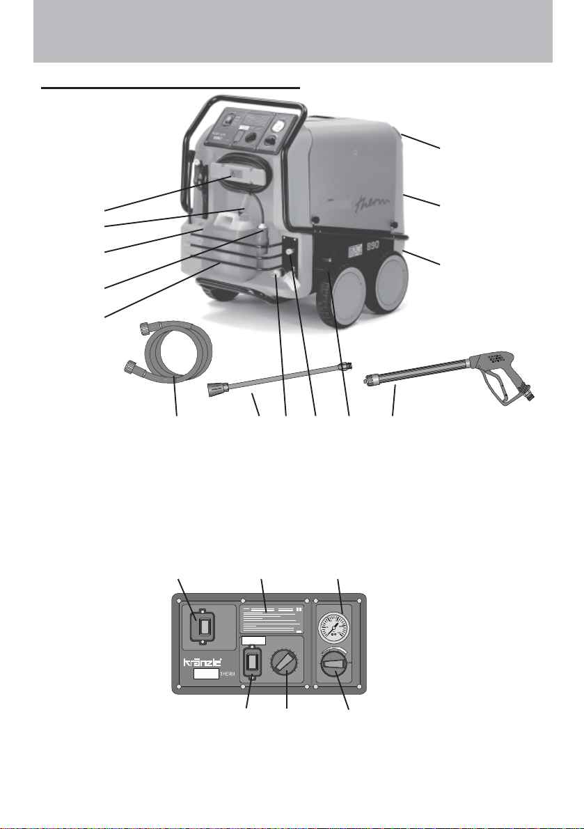
Description
Construction and Function
12
3
4
8
2
10
5
1 Water inlet connection with filter
2 Power cable
3 Winder for cable
4 Suction hose for detergent
5 High pressure hose
6 Spray gun
7 Spray pipe attachment
,,,
15 16 17
Hauptschalter
Main Switch
71139 6
8 Storage bin for spray gun and pipe
9 Brake
10 Storage bin for accessories
11 Fuel tank
12 Filler aperture for fuel
13 High pressure outlet
14 Fuel drainage screw
Hauptschalter
Pressur e
150
150
100
100
200
200
50
50
bar
bar
250
250
0
Wassertemperatur
Water temperature
50
40
30
20
10
0
70 80
60
°C
0
90
Zu Auf
100
off0on
110
120
130
140
150
Hauptschalter
Cleaning liquid
11
14
18.1
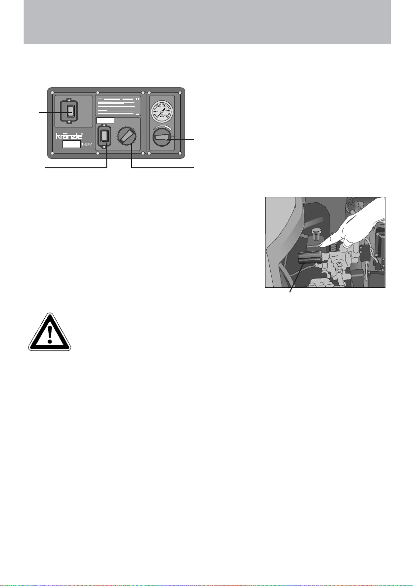
15 Master switch (appliance On- Off)
16 Brief operating instructions
17 Manometer
1918
18 Thermostat
18.1 (Burner ON- OFF) ignition
19 Detergent dispensing valve
3
Page 4
Description
Water system
The water flows into a tank.
A float valve regulates the water intake.
The water is then directed to the safety spray pipe
under pressure from the high pressure pump.
The high pressure spray is formed through the nozzle
on the spray pipe.
Detergent and caring system
The high pressure pump can also suck a detergent/caring agent and mix it with the
high pressure jet. - The detergent must have the ph-value 7-9 neutral.
Only open the dosing valve, if the chemistry sieve is placed in a
liquid.
The rules concerning the environment, refuse and ground water
protection must be complied with!
Pressure control and safety facilities
The pressure control valve allows full adjustment of the
quantity and pressure of the water.
The safety valve protects the machine from excessive
pressure and cannot be adjusted beyond the admissible
operating pressure. The setting nuts are sealed with
lacquer.
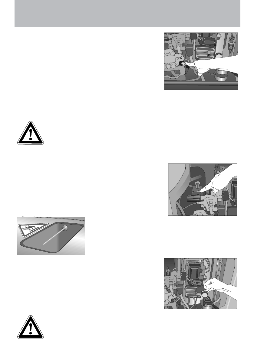
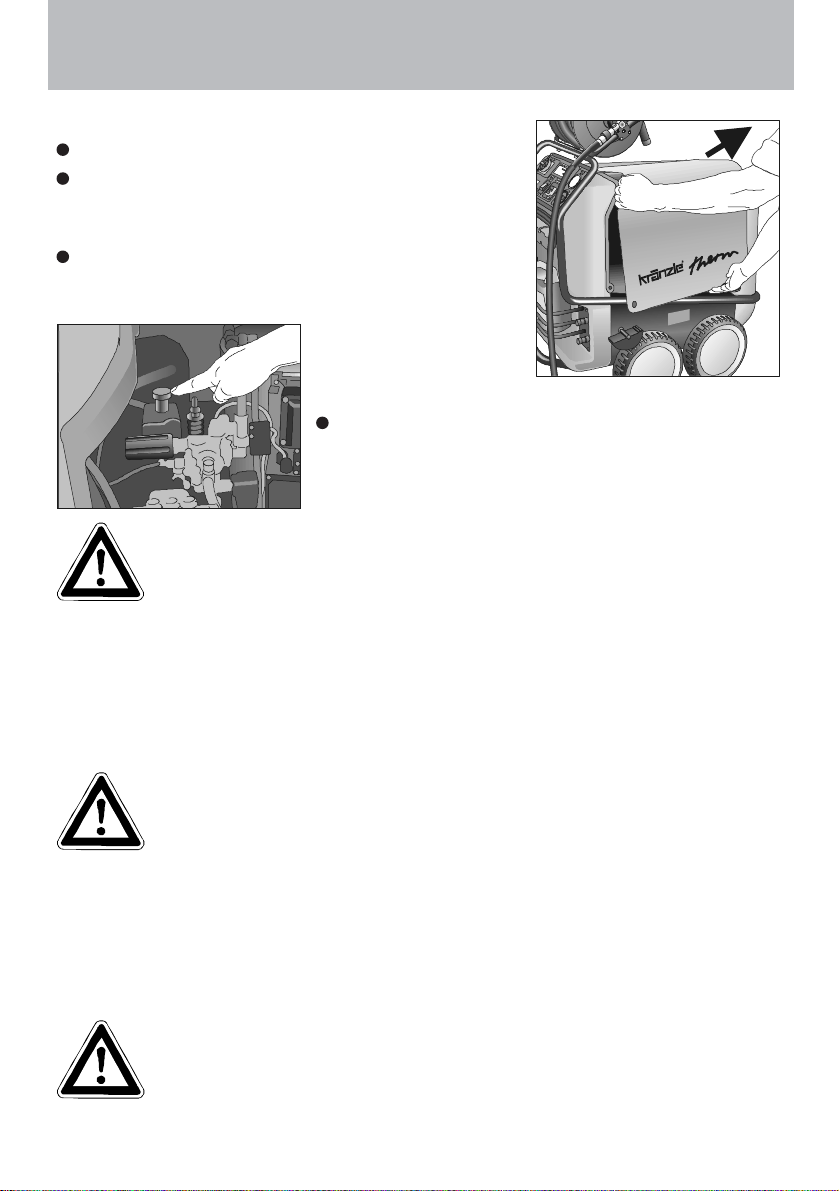
As an additional safety feature against overheating of the
combustion chamber a temperature sensor is installed in
the chimney. This sensor switches off the burner motor,
the ignition transformer and the solenoid valve as soon as
the exhaust gas temperature exceeds 250° C.
You find the unlocking button for the excess
temperature release on the console fixed to the
combustion chamber below the ignition transformer.
The machine has to rest for approx. 15 minutes before
it is allowed to press the unlocking button. If the
excess temperature sensor switches the machine off
repeatedly please call the technical service.
Replacements, repairs, new adjustments and sealing operations
may only be performed by trained personnel.
4
Page 5
Description
Motor protection switch
The pump motor is protected from overload by a motor
protecting switch. In case of an overload the motor is
switched off by the motor protecting switch. In case the
blue button is not set to „automatic resetting“, it has to
be pushed in again by hand. In case of a repeated
switching off of the motor by the motor protecting switch
the cause of the malfunction has to be removed.
Replacement and inspection work may
only be performed by trained personnel.
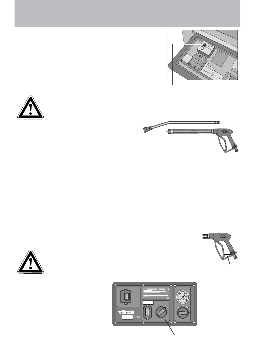
Spray pipe with spray gun
The spray gun only allows the machine to be
operated when the safety trigger is pulled.
The spray gun can be used when the safety trigger is pulled. The liquid is
then pumped up to the nozzle. Spray pressure builds up and quickly reaches the
selected operating pressure.
When the trigger is released the gun is closed, which prevents any further liquid
from coming out of the spray pipe.
The recoil resulting from the gun being closed opens the pressure control valve in
the machine. The pump remains switched on and pumps the circuit with reduced
overpressure. When the gun is opened (trigger pressed) the pressure control valve
closes and the pump starts to operate again at the selected pressure.
After completing work with your Kränzle therm, or if work is interrupted, the
safety catch (1) must be applied. This makes it impossible to press
the trigger by accident.
Blue button in the
unfolded control panel
The spray gun is a safety device. Repairs may only be
performed by trained personnel. If spare parts are
required, use only those approved by the maker.
Thermostat
The thermostat with rotary control
switch controls the temperature
of the spray water.
Hauptschalter
Main Switch
Wassertemperatur
Water temperature
50
40
30
20
10
0
1
Hauptschalter
Pressure
150
150
100
100
200
200
50
50
bar
bar
250
250
0
70 80
60
°C
0
90
Zu Auf
100
off0on
110
120
130
140
150
Hauptschalter
Cleaning liquid
Thermostat with
rotary control switch
5
Page 6
Safety Information
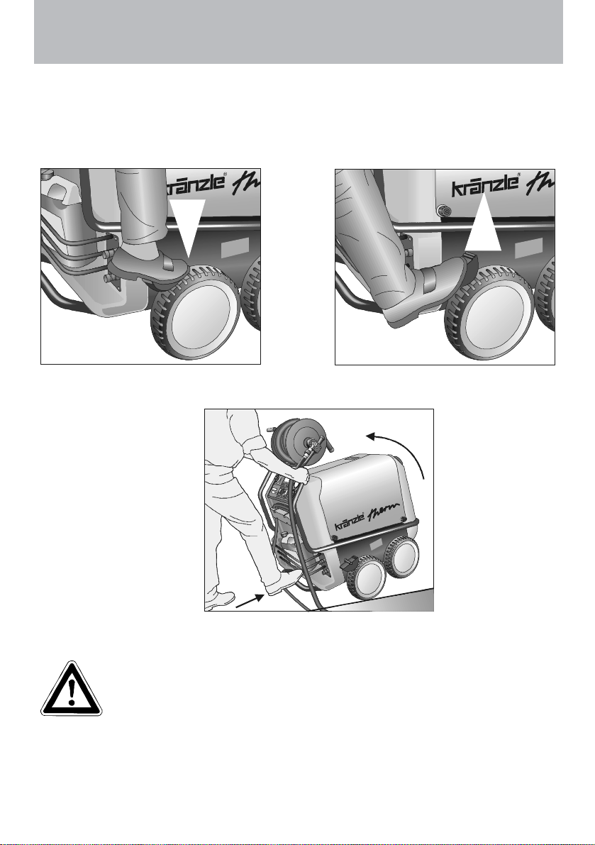
Brake
The Kränzle therm is fitted with a brake that prevents the machine from rolling away
on flat ground.
Always apply the brakes firmly when working with the machine !!!
Brake applied
If you want to move the
high pressure cleaner
into another direction,
first slightly tilt back the
machine by pressing the
foot rest and pulling the
pushbar at the same
time.
Brake not applied
Now you can
move the cleaner
into the desired
direction.
Safety Information
CAUTION !!!
For safety reasons always put the master switch into the „0“
position (=power switch-off) after completion of work.
When starting the cleaning process do not aim the high pressure jet at the
object to be cleaned for at least 30 seconds.
It is possible, that the water contents in the combustion chamber (approx. 5 litres) has
changed colour due to the resting time.
6
Page 7
Description
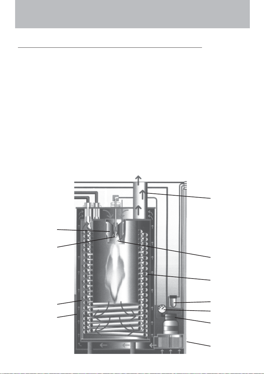
Heat exchanger
Heating coil: 34 m long - Content: 5 l of water – Heating capacity: 70 k W
The heat exchanger is heated by a high pressure fan heater.
A ventilator (1) draws in the cold, fresh air from the bottom end of the machine and forces
it upwards between the outer mantle (2) and the inner mantle (3). In the process, the
fresh air is pre-heated and the outer mantle of the heat exchanger is cooled.
The pre-heated air is pressed through a mixing unit (4). Here finely atomised fuel is
injected via a nozzle (5) and mixed with the air. The electrodes (6) located below then
ignite the fuel-air mixture.
The flame burns from top to bottom, turns round and the hot gas flows past the heating
coil (7) on its way back up. The burned gases collect in the exhaust chamber and are
emitted from the chimney (8).
The water is forced through a heating coil by the high pressure pump. Hot air flows
around the coil, as described above.
The fuel pump (9) draws the oil through a filter (10) and pumps it to the injector nozzle (5).
The surplus quantity of fuel flows straight back into the tank. The oil pressure (approx. 10
bar) is shown on the fuel manometer (11).
8
4
5
6
7
3
2
10
11
9
1
7
Page 8

Safety Information
Safety Information
Important!!!
The machine must be disconnected from the power supply when
servicing work is being carried out. The master switch should be
in position "0" and the plug out of the socket.
Do not use the cleaner if electrical connections or other safetyrelevant parts (e.g. o verpressure valve, high pressure hose,
spraying equipment etc.) are damaged.
The machine may only be used by persons who have received
the necessary training.
Never operate the machine without supervision.
The water spray can be dangerous. It should never be directed at people, animals,
electrical apparatus or the machine itself.
Never direct the spray at power sockets.
Parts of the machine interior and parts of the gun and lance become hot when hot
water is used. Leave the cover of the machine closed when using the machine and do
not touch the metallic parts of the gun and lance.
Children must not use high pressure cleaning equipment.
Do not damage the cable or repair it incorrectly.
Do not pull the high pressure hose if there are kinks or loops in it. Make sure that the
hose is not damaged on sharp edges.
Persons operating the machine should wear the necessary protective clothing, ie, waterproof clothing, rubber boots, safety goggles, headwear etc. It is prohibited to use the
machine in close vicinity to people lacking suitable protective clothing.
The high pressure spray can generate a high level of noise. If noise exceeds the
maximum allowed levels, users and others in the vicinity must wear suitable ear protection.
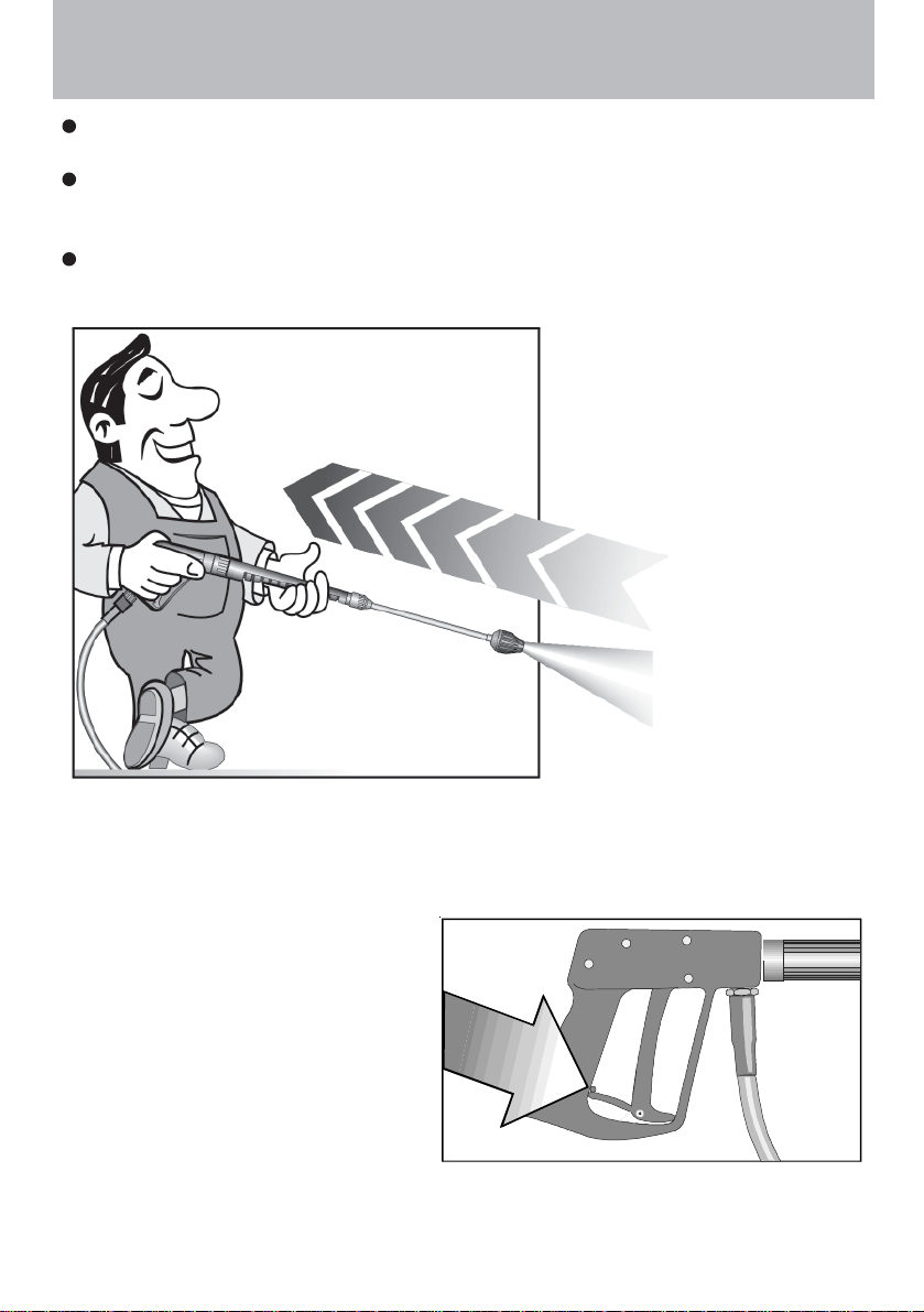
The high pressure spray causes recoil and additional twisting movement if the gun is
angled. The gun must therefore be held firmly with both hands. (see page 2)
Do not close off the exhaust aperture on the topside of the machine. Do not bend over
this aperture and do not put your hands inside it. Exhaust gases are very hot!
Do not clamp down the trigger of the gun. Apply the safety catch after use, in order to
prevent accidental spraying.
Do not spray against matter containing asbestos or other hazardous substances.
Never spray liquids containing solvents, such as paint thinner, petrol, oil, or anythng
similar. Note the specifications of the additive makers! The seals in the machine are
not resistant to solvents. The spray vapour of solvents is highly inflammable, explosive
and poisonous.
8
Page 9
Safety Information
The machine may not be set up and used in rooms where there is a danger of fire or
explosion. The machine may not be used under water.
Air is required for combustion, and exhaust fumes are generated. If the machine is used
in closed rooms, make sure that the exhaust fumes can escape and that there is
adequate ventilation.
Use light heating oil EL (DIN 51 603) or Diesel (DIN EN 590) only. The use of other fuel
is perilous and may even cause an explosion.
As to the recoil see notice on page 2!
Apply the safety catch on the
spray gun after each use, in
order to prevent uninten-
tional spraying!
9
Page 10
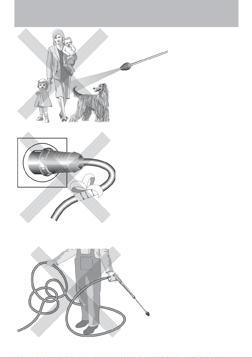
This is prohibited!
Never direct the
water jet at people
or animals!
Do not damage the
power cable or
repair it incorrectly!
10
Never pull the high
pressure hose if it
has formed kinks or
“nooses”!
Never pull the hose
over sharp edges!
Page 11
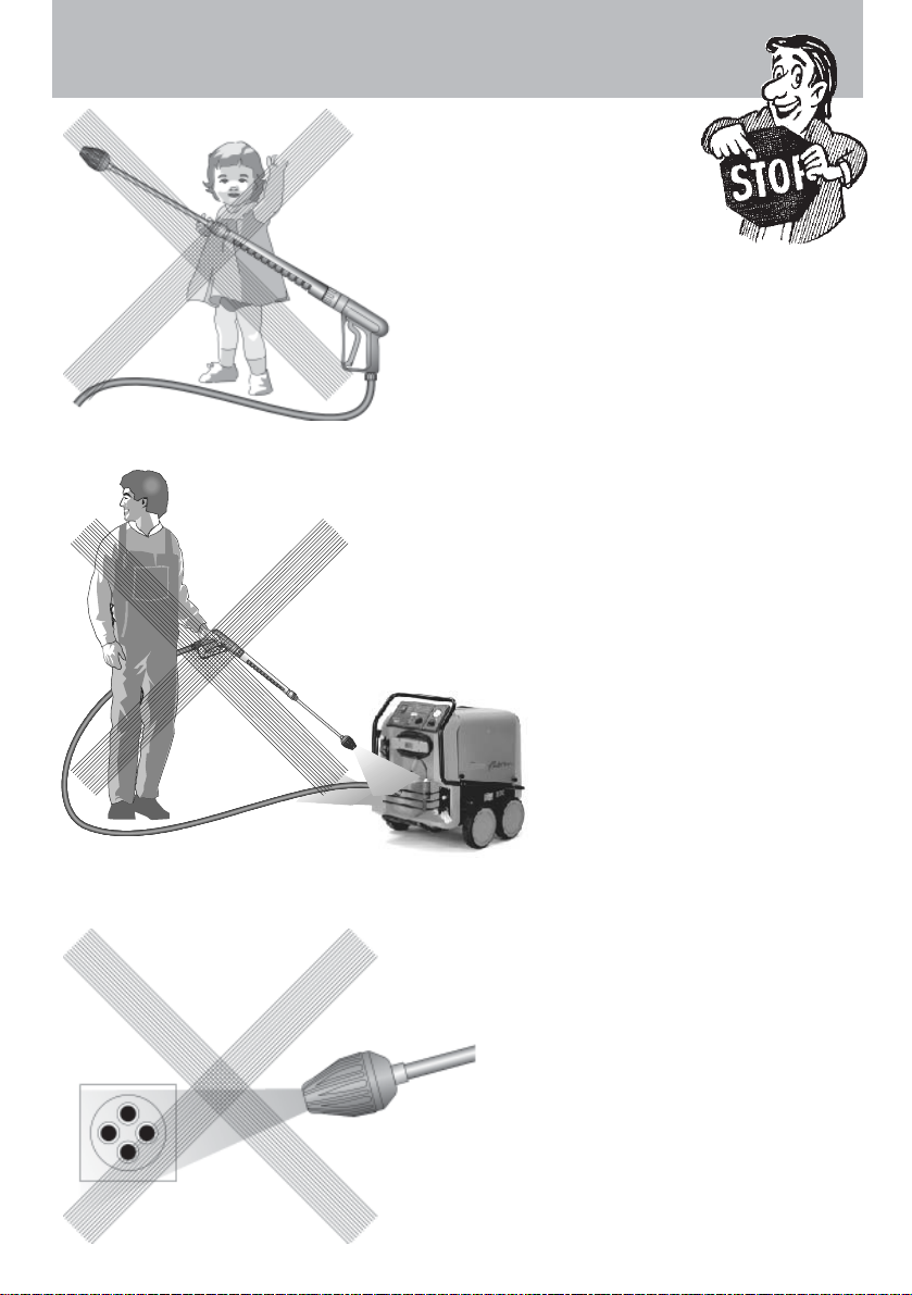
This is prohibited!
Never allow
children to use the
high pressure
cleaner!
Never direct the
water jet at the
machine itself!
Never direct the
water jet at a
power socket!
11
Page 12

Commissioning
Electrical connection
The voltage given on the specification plate must match the mains voltage.
The machine is supplied with a power cable and plug.
The plug must be connected to a properly installed electrical socket with
earthing and have a 30 mA FI residual current circuit breaker . The socket
must have a neutral 16A fuse on the mains side.
If an extension cable is used, it must have an earth line that is properly connected to the
plug connections. The lines in the extension cable must have a cross section of at least
1,5 mm². The plug connections must be of spray protected design and may not lie on a
wet surface. (If the extension cable is longer than 10 m the minimum cross section is
2,5 mm²)
Important!
Extension cables that are too long cause a drop in the voltage and thus
interruptions in operation. If you are using a cable drum, the cable must
always be fully unwound.
Brief operating instructions
To be found on the machine.
1. Connect the high pressure hose with the spray gun and lance to the machine.
2. Connect the water supply and turn on the tap.
3. Connect to the electrical supply.
4. Switch on the machine with the spray gun open and start the washing procedure.
If the system has to be de-aerated (machine vibrates), open and close the gun
several times.
5. When using the machine as a cold water high pressure cleaner:
ignition "OFF" - Set thermostat with rotary control switch to 0 °C.
6. When using the machine as a hot water high pressure cleaner:
ignition "ON" - Set thermostat with rotary control switch to min. 40 °C
7. When using the machine as a hot water high pressure cleaner:
preselect the water temperature with thermostat to min. 40° C
High pressure hose and spray equipment
The high pressure hose and spray equipment supplied with the machine are made of
high quality material specially adapted for the operating conditions of the machine, and
are properly marked.
If spare parts are required, only properly marked components approved by
the maker should be used. High pressure hoses and spray equipment
must be connected so that they are pressure-tight. The high pressure
hoses should not be driven over, pulled excessively or twisted. Do not pull
the hose over sharp edges, since this will invalidate the warranty.
12
Page 13
Commissioning
Commissioning
Secure the machine by applying the brake.
Open the right cover of the machine (without
chimney) and check the oil level of the high
pressure pump.
Do not start the machine if there is no oil on the
dipstick. Fill oil if necessary.
Fill the fuel tank with light heating oil prior to
use.
Use EL heating oil (DIN 51603) or diesel fuel only
Unsuitable fuels, such as petrol, may not be used (danger of
explosion)
Water connection
Connect the machine to a water tap using a hose of at least 1/2" and turn on the tap.
The water tank in the machine fills up. When the tank is full, the built-in float valve
closes the water inlet.
Use clean water only!
Follow the instructions of the local water supply utility .
Connection of the machine to drinking water mains must be in
accordance with EN 61 770.
High pressure connection
Connect the high pressure hose to the handgun.
Unwind the hose so that it is free of loops and connect it to the handgun and the
machine.
Check that all screw-type connections are pressure-tight. Leaks
from gun, high pressure hose or hose drum must be eliminated
immediately. Leakage leads to increased wear.
13
Page 14
Commissioning
Electrical connection
- Check that the master switch (1) is off (position "0").
Connect the power cable to a properly
installed electrical socket with earthing
and a 30 mA FI fault current safety
switch. The socket must have neutral 16A
fusing on the mains side.
3
2
1
1A
Hauptschalter
Main Switch
Wassertemperatur
Water temperature
50
40
30
20
10
0
Hauptschalter
Pressur e
150
150
100
100
200
200
50
50
bar
bar
250
250
0
70 80
60
°C
0
90
Zu Auf
100
off0on
110
120
130
140
150
Hauptschalter
Cleaning liquid
- Switch off the ignition. Rocker switch (1A) to „0“.
- Set the pressure control (4) valve to maximum
pressure (see on page 12) and close the detergent
valve (3).
- Open the gun and switch the master switch on.
The high pressure pump now presses the air out of the
lines, and after a short time the high pressure spray
forms and the operating pressure is reached.
(Open and close the gun repeatedly)
The machine is fitted with a Total-StopSystem. If the gun is closed for longer
than approx. 20 seconds, the machine switches off automatically,
after 20 minutes the machine moves to safety switch off and you
must use the main switch to turn it back on.
The machine restarts automatically when the gun is operated,
provided that the master switch is on.
4
Usage as a cold water high pressure cleaner
- Leave the ignition "OFF". Rocker switch (1A) to „0“.
- Start cleaning
Usage as a hot water high pressure cleaner
- Set the target temperature on the thermostat to min. 40 °C and than switch the
ignition "ON" (rocker switch).The oil burner starts to work. The water is heated up
and kept at the temperature you have set.
Steam level
To reach the steam level, i.e. over 90 ° C water temperature, open the right cover on
the housing (see page 13) and adjust the pressure or water quantity on the hand
wheel (4) downward and use the thermostat with rotary switch to select the
temperature up to a maximum of 150 °. In the case of machines with hose drums,
the high pressure hose must always be unwound completely.
14
Page 15
Decommissioning
Usage with detergents
- The detergent must have the ph-value 7-9 neutral.
- Wait until the pump has pressed the air out of the lines
- Put the chemical filter into a container with detergent
- Open the detergent valve.
The pump now draws detergent in and mixes it with the high pressure spray.
- Set the desired concentration of detergent.
- At the end of the working procedure with detergent reset the rotary button to „O“.
- When the high pressure cleaner is operated with open chemistry valve
without chemicals, the pump sucks in air. Damages caused to the pump as
a result are not covered by the guarantee.
Comply with additive manufacturers’ instructions (e.g. protective
equipment and waste water regulations). Use only additives
approved for use with high pressure cleaners. Using other additives
impairs the safety of the machine.
In the interests of the environment and to keep expenditure down,
we recommend sparing use of detergent. Please observe the
recommendations of the detergent manufacturer.
After using detergents, rinse the machine for approx. 2 minutes by
pressing the trigger of the spray gun.
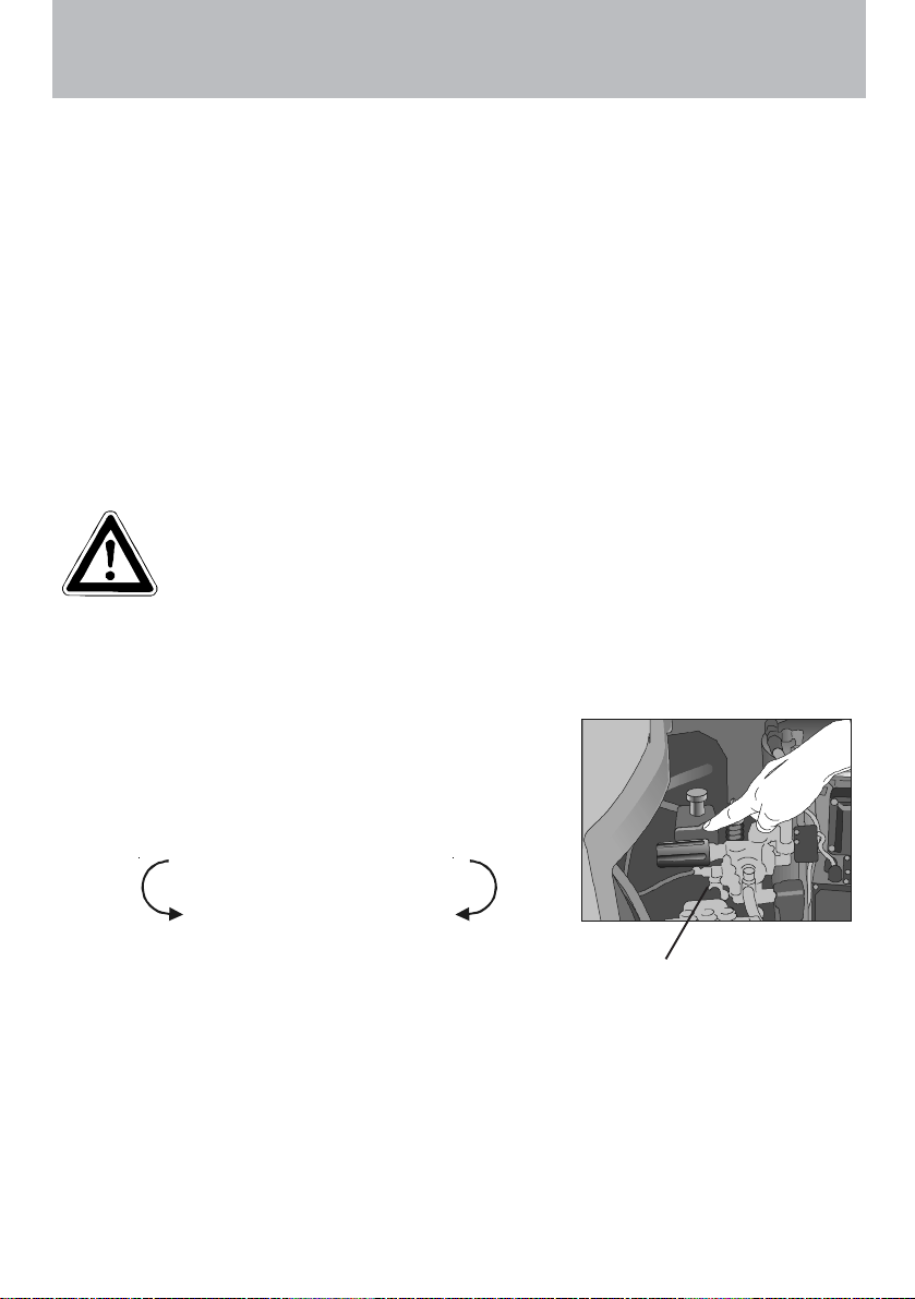
Adjusting the pressure
Use the pressure control valve (4) directly on the
pump head to adjust the pressure.
turn left:
min.
Decommissioning
- Switch off the master switch (position "0").
- Pull the plug out of the power socket.
- Turn off the water supply.
- Open the gun until the pressure is gone.
- Lock the gun.
- Disconnect the water hose.
- Slacken the connections of the high pressure hose and gun and unscrew the high
pressure hose from the machine (appliances without hose drum).
turn right:
max.
4
15
Page 16

Care and Maintenance
Anti-Freeze Protection
The machine is normally still partially filled with water after work has been completed. It
is therefore necessary to take special precautions to protect the machine from frost.
- Completely empty the machine of water.
Disconnect the machine from the water supply and switch off the ignition.
Switch on the master switch and open the gun. The pump now presses the
remaining water out of the heating coil. Do not allow the machine to run for
longer than a miniute without water.
- Fill the machine with anti-freeze
If the machine is not in use for lengthy periods of time, it is advisable to
pump anti-freeze into the machine, especially in winter.
freeze agent into the water box and turn on the machine without ignition (rocker
switch to „0“). Wait with opened gun, until the agent comes from the nozzle.
However, the best protection against frost is to keep
the machine in a place that is safe from frost.
Care and Maintenance
Care and maintenance is required to keep the machine in good working order, and
to allow you to enjoy the machine for as long as possible.
IMPORTANT!!!
Always remove the plug before working on the machine!
For this purpose, fill the anti-
What to do!
- Weekly, or after approx. 40 hours of operation
Check the oil level of the high pressure pump.
Loosen the red oil stopper on the high pressure pump and pull out the oil
measuring rod.
If the oil level is too low, add oil until the oil level is between the two markings on
the oil measuring rod.
Change the oil if it has a grey or whitish appearance. The oil should be
disposed of responsibly.
Check the filter in front of the float valve in the water tank and the fuel filter
in front of the solenoid valve. Clean the filters if necessary.
- Yearly, or after approx. 500 hours of operation
Desulphurise and decarbonize the heating coil.
Check the oil burner and ignition system
Clean the oil nozzle, oil filter, soenoid valve and filter, clean and adjust the
ignition transformer, ignition cable and ignition electrodes and replace defective parts
Changing the oil
16
Page 17
Care and Maintenance
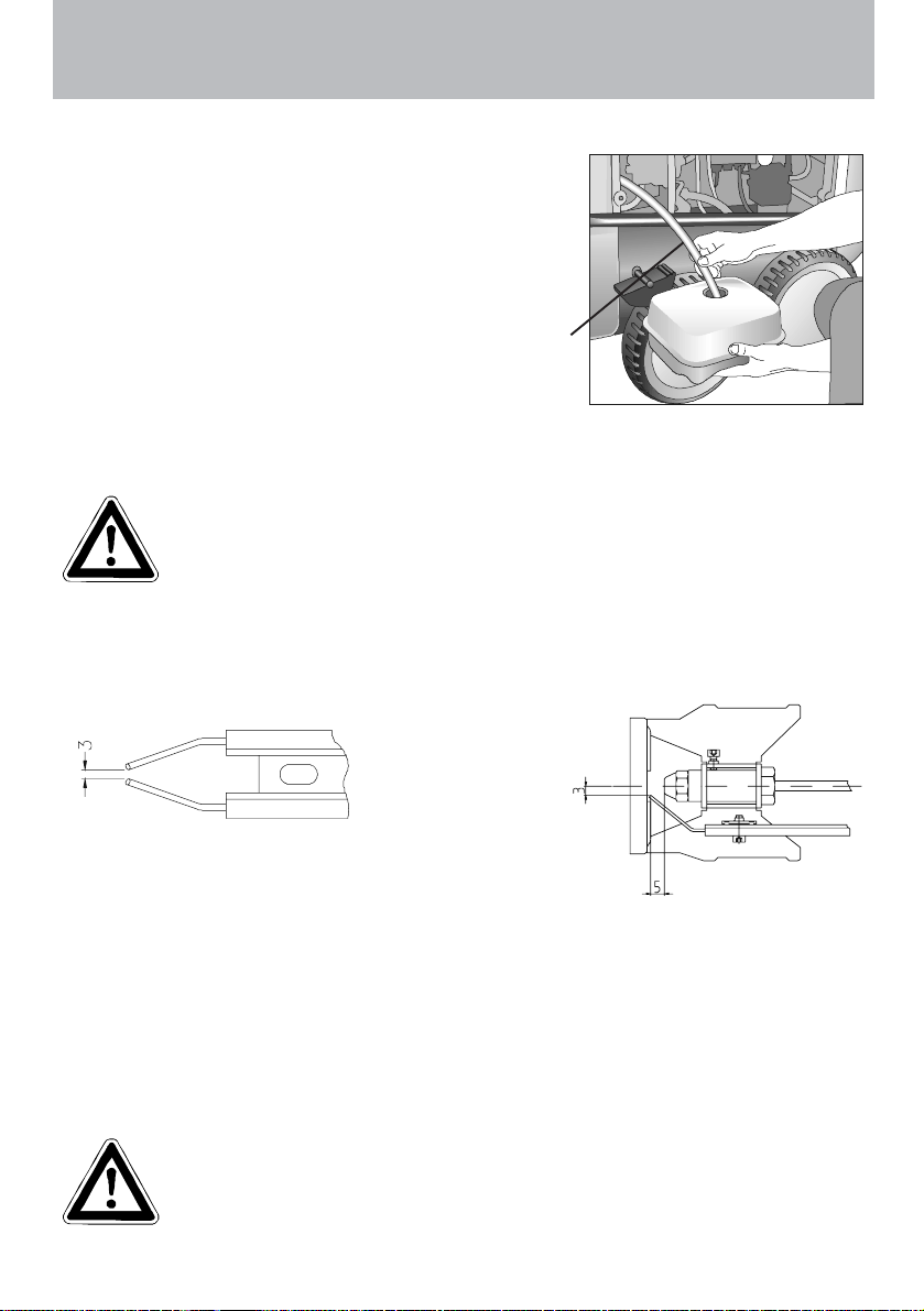
Changing the oil
To do this, take the oil drainage hose (1)
connected to the oil drain screw, from the inside
of the machine and open the red oil filler cap on
the top side of the black oil reservoir. Open the
cap at the end of the hose. Drain off the oil into
an oil pan and dispose of it responsibly. Close
the end of the hose.
Refill with oil as described above.
Oil leakage
If oil leaks out, go to the nearest customer service immediately (dealer). (Environmental damages, transmission damages, loss of guarantee.)
Type of oil: Formula RS of Castrol - Quantity: 1.0 l
Adjusting ignition electrodes
For a smooth ignition, the setting of the ignition electrode must be controlled
regularly.
1
Check distance in mm
Fuel System
Your fuel may contain particles of dirt, or impurities or water may get into the tank
during refuelling. Check the tank for impurities on a regular basis. Clean the tank
when necessary
Empty the fuel tank using the drainage screw at the bottom of the tank. Clean the
tank and fuel lines. Clean tank and fuel lines carefully and check to see whether
there are water droplets on the inside of the tank, because these must be removed.
Detergent and dirty fuel must be disposed of responsibly.
17
Page 18

Care and Maintenance
Decalcifying the heating coil
Calcified machines use an unnecessary amount of energy because the water can only
be heated slowly and the excess pressure valve feeds a part of the water back into the
pump circuit.
Calcified machines can be recognised by increased pipeline resistance.
Check pipeline resistance by disconnecting the high pressure lance from the gun
and switching the machine on. A full jet of water emerges from the gun. The
machine must be decalcified if the pressure shown on the manometer is greater
than 25 bar.
Decalcifiers are caustic!
Observe the instructions for usage and accident prevention. Wear
protective clothing to prevent the decalcifying agent from
contacting your skin, eyes and clothing (eg, gloves, safety mask
etc.)
Proceed as follows to decalcify the machine:
Unscrew the high pressure hose from the machine and decalcify it separately.
Put the detergent suction hose into a container of decalcifying solution.
Set the dispenser valve to the maximum concentration.
Switch on the machine.
Hold the gun in a separate container and press the trigger.
Wait for about a minute until the decalcifier comes out of the gun
(recognisable by its whitish colour).
Switch off the machine and allow the solution to act for about 15-20 minutes.
Switch the machine back on and rinse it through with clear water for about 2
minutes.
Now check whether pipeline resistance is back to an acceptable level. Repeat the
decalcifying process if the pressure without the high pressure lance is still above 25
bar.
18
Page 19

Care and Maintenance
Rules, directives, inspections
Inspections performed by Kränzle
- measurement of earth line resistance
- measurement of voltage and current
- inspection of tension consistency with +/- 1530 V
- pressure check of heating element at 300 bar
- visual and functional check as per the inspection sheet provided
- exhaust fume analysis (see test strips provided)
Guidelines for liquid sprayers
The machine conforms with the "Guidelines for liquid sprayers". These
guidelines are issued by the organisation of trade associations and may be
obtained from Carl Heymann-Verlag KG, Luxemburger Str. 49, 50939 Köln.
These guidelines specify that this machine is to be inspected by qualified
personnel whenever necessary, but no less than once every 12 months.
These inspections must be recorded in the inspection log at the end of this
manual.
Pressure container and steam boiler directives
Kränzle high pressure cleaning equipment conforms to the pressure container
and steam boiler directive. No construction approval, notification of licence and
takeover inspection are required. The water capacity is less than 10l.
Duties of owner
The owner is to ensure before the sprayer is used that all safety-relevant
components are in a serviceable condition. (e.g., safety valves, hose and electric
cables, spray equipment etc).
Emission control legislation
With stationary installation, the emission levels of the machine must be checked
once a year by a qualified organisation or person according to German law.
The first inspection must be carried out four weeks after the machine is
commissioned. The owner is responsible for having the inspection performed.
19
Page 20

Description of function - Troubleshooting
IMPORTANT!!!
Always remove the plug before working on the machine!
Hauptsc ha lt er
Main Switc h
1
1A
40
30
20
10
Wassertemperatur
Water te mp er at ure
60
50
0
3
Hauptschalter
Pressure
150
150
100
100
200
200
50
50
bar
bar
250
250
0
0
70
80
90
Zu Auf
off0on
100
110
120
130
140
150
Haupts cha lt er
°C
Cleaning liquid
1 Master switch
1A Ignition “ON/OFF
2 Thermostat with rotary switch
3 Brief operating instructions
2
17 18
13
12
6
4
7
8
5
11
14
10
15
16
20
22
19
9
21
4 Hand wheel for pressure adjustment
5 High pressure pump
6 Pressure switch black (start solenoid
valve)
7 Pressure switch red (start pump)
8 Safety valve
9 Motor for ventilator and fuel pump
10 Solenoid valve (Fuel)
11 Terminal box
12 Ignition transformer
20
13 Thermosensor water
14 Excess temperature release
15 Fuel manometer
16 Fuel pump
17 Ignition electrodes
18 Thermosensor exhaust gas
19 Fuel tank
20 Ball cock fuel
21 Ventilator
22 Fuel filter
Page 21

Description of function - Troubleshooting
Cold water mode
1. Connect to water supply and determine whether the water tank fills up completely
and the float valve stops.
2. Ignition (switch 1A) to OFF.
3. Main switch to ON.
4. Open high pressure gun. The pump sucks water from the water tank and moves
the water through the heating coil to the lance, the pressure is increased.
After you close the gun, press the red pressure switch (7). The 20-Second-Stop
system is activated, i.e. after closing the gun, the pump motor is turned off after 20
seconds. When you open the gun the motor starts again.
If the gun stays closed for more than 20 minutes, the safety switch off is activated
and the machine is turned off completely, i.e. if you want to use the machine you
must first turn it OFF and then ON with the main switch.
A TTENTION!!
If the pressure is not built up immediately , there is still air
in the pump. Open and close the gun repeatedly to press
the air from the machine.
Hot water mode
Start the machine just like in cold water mode and then turn the rocker switch for the
burner to ON. Then, turn the rotary switch on the thermostat, (2) located on the front,
to the desired temperature (at least 40 °C) in order to activate the burner, i.e., that fuel
is injected.
The manometer (15) on the fuel pump shows approx. 10 bars. If this display is missing, check whether
1. there is heating oil in the tank
2. the fuse in the terminal box ( 11 ) for the motor ( 9 ) has blown.
3. the fuel sieve (22) or the fuel sieve in the pump (16) is dirty.
4. the ball cock (20) is closed.
5. the fuel pump does no operate smoothly or is blocked.
6. the ventilator jams.
The thermostat grants permission to open the solenoid valve; after opening the gun,
the burner starts. If the solenoid valve is open, the fuel pressure is approx. 10 bars.
The burner starts and heats the water to the temperature preset by you. When the
temperature is reached, the burner turns off. If the temperature drops again, the
burner switches back on automatically, so that you continuously have the desired
temperature.
21
Page 22

Description of function - Troubleshooting
The thermostat with rotary switch is controlled by a thermosensor, mounted to the
outlet of the heating coil.
In the electro distributor box (11) mounted to the combustion unit, there is a fuse,
which protects the motor (9) for the fuel pump and ventilator. If the motor is overloaded,
the fuse blows. This can happen when the fuel pump is blocked or does not work
freely, when the ventilator is blocked or does not operate freely or when there is an
electrical problem.
There is a thermosensor (18) in the waste gas tube, which controls an excess
temperature relay with trigger function (4), i.e. when the exhaust gas temperature in
the chimney increases above 230 °C, this relay triggers. To activate it again, you must
wait until the combustion unit has cooled, i.e. approximately 15 minutes. Then, you
can press the button under the cover (14) again. The excess temperature relay can
trigger when the machine is operated over a longer period in the highest steam level, or
when there is lots of soot on the heating coil due to poor combustion, or when the
inside of the heating coil is calcified, so that there is no ventilation (cooling).
As further safety function, the burner is also switched off, when the water
temperature exceeds 147 °C.
1
Hauptsc ha lt er
Main Switch
30
20
10
Wassertemperatur
50
40
0
Water te mpe r atur e
60
3
Hauptschalter
Pressure
150
150
100
100
200
200
50
50
bar
bar
250
250
0
0
70 80
90
Zu Auf
off0on
100
110
120
130
140
150
Haupts cha lt er
°C
Cleaning liquid
1A
2
1 Master switch
1A Ignition “ON/OFF
2 Thermostat with rotary switch
3 Brief operat. instruction
4 Hand wheel for pressure
adjustment
5 High pressure pump
6 Pressure switch black
7 Pressure switch red
8 Safety valve
9 Motor for ventilator and fuel
pump
10 Solenoid valve (Fuel)
11 Terminal box
12 Ignition transformer
13 Thermosensor water
14 Excess temperature release
15 Fuel manometer
16 Fuel pump
17 Ignition electrodes
18 Thermosensor exhaust gas
19 Fuel tank
20 Ball cock fuel
21 Ventilator
22 Fuel filter
22
17
18
13
12
6
7
4
8
5
11
14
10
15
16
20
22
19
9
21
Page 23

Troubleshooting
IMPORTANT!!!
Always remove the plug before working on the machine!
Malfunction Cause of malfunction / Trouble shooting
Water supply
Water tank runs over.
Water tank does not fill
completely.
Pump does not suck.
Test: check water and chemical
system for tightness.
High-pressure pump
Pump makes lots of noise.
Operating pressure is not
reached.
Water drops from the pump.
Oil drops from the transmission.
Pressure is too low
Machine does not switch off
Test: Disconnect pressure switch
(red) bridge on the panel
between terminal 5 + 6
Float valve is dirty.
Float valve is defect.
Water filter is dirty.
Check water inlet quantity.
Valves stick or are dirty.
Suction hose leaks.
Chemistry valve is open or leaks.
Check hose clips (connections).
High-pressure nozzle is clogged.
Connect water inlet directly to the pump (2-4 bar
pre-pressure).
Pump sucks air. Check suction connections.
Check high-pressure nozzle.
Check valves.
Check O-rings under valves.
Check sleeves.
Manometer is defect.
Unloader: check stainless steel seat and ball.
Check seals on the control piston.
Replace sleeves in the pump.
Replace O-rings.
Check oil seals (replace).
Check plunger and plunger guides.
Check water supply, since water deficiency or air
suction can cause damage to seals and O-rings
(chemistry valve leaks?).
Worn high pressure nozzle
Stainless steel seat, ball, O-ring in unloader is dirty
or defect.
Manometer is defect
Check return body and O-ring in unloader of the
valve housing.
Check pressure switch (red).
Check micro switch.
Check cable connections.
Board is defect.
23
Page 24

Troubleshooting
Malfunction Cause of malfunction / Trouble shooting
Machine does not start
Heating (burner)
Fuel pump/blower operates, but
burner does not heat.
Fuel pump/blower does not operate.
- Pump makes lots of noise
- Fuel operating pressure has not been
reached
Coupling between burner motor and
fuel pump is broken
Sole noid valve on the fuel pump
does no t op en
Test: Pressure switch (black)
Bridge in terminal box between
terminal 3 +4
Test: Connect solenoid valve 230 V
externally
Oil pressure on the fuel pump is
too low
too high
Check electricity supply.
Check main switch.
Check cable connections.
Check board.
Check pressure switch.
Switch off by overcurrent release.
Set water temperature is reached.
Increase temperature on thermostat with rotary
control switch.
Open gun, until temperature drops.
Fuel tank is empty.
Fuel filter is dirty.
Fuel nozzle is dirty.
Float switch in fuel tank is defect.
Blower/fuel pump motor is defect.
Check electrical equipment.
Check fuse in terminal box.
Coupling between burner motor and fuel pump is
defect.
Water in fuel tank.
Dirt or rust in the fuel pump.
Clean tank.
Replace fuel pump.
Check pressure switch (black).
Solenoid valve is defect or dirty.
Clean filter, clean supply line, clean fuel pump.
Setting is wrong.
Clean fuel nozzle, or replace it.
24
Page 25

Troubleshooting
Malfunction Cause of malfunction / Trouble shoooting
Ignition does not function
Ventilator does not operate
Check ignition cable.
Charring of plug-in contacts by moisture.
Cable is broken
Check ignition transformer connections.
Transformer is defect
Ignition electrode has been falsely set or burnt up.
Burning
Smoke during operation
Smoke after switching off
Spray gun -
High-pressure hose
Gun drips
High pressure hose drips
Nozzle is clogged
Sucking detergent
Detergent is not sucked
Blower-/fuel pump motor is defect.
Check electrical equipment.
Check fuse in terminal box.
Coupling between burner motor and fuel pump is
defect.
Fuel is dirty.
Nozzle or nozzle stock leaks.
Water in tank.
Check for leakages.
Replace seals.
Replace O-ring under screwed connection.
Manometer indicates pressure, but no water comes
out of HP-hose – clean nozzle.
Pump sucks air.
Check hose clips.
Test:
Connect water line to the pump.
Water inlet: 2 - 4 bar pre-pressure. No water must
come from the detergent hose.
25
Page 26

Guarantee
A
Warranty
This warranty covers material and/or workmanship related defects only and does not
extend to ordinary wear.
Machine must be operated according to enclosed operating instructions which are part of
present warranty conditions.
ll products sold directly to private customers are warrantied for a period of 24 months,
whereas the warranty period for industrial purchases is limited to 12 months.
In case of any warranty claims, please have your HP cleaner together with accessories
and your purchase document ready and contact your nearest dealer or authorized service
point which can also be looked up in the internet at www.kraenzle.com
Warranty is void in case of attempts to modify any of the safety devices or in the event of
exceeding temperature or rpm limits - this also applies to undervoltage, low water and/or
polluted water. Gauge, nozzle, valves, sealing gaskets, high pressure hose and spray
equipment are considered wear parts and do not fall under this warranty.
.
26
Page 27

A1 Ignition transformer
B1 Thermostat
F1 Fuse 3.15 timelag
K3 Motor contactor
M1 Motor, HP pump
M2 Burner motor
Q1
Q1 Master switch
Q2 Burner switch
S1 Excess temperature release
Circuit diagramme
S2 Pressure switch delayed motor cut-out
Q2
K3
with delayed
motor cut-out
Control board
S3 Pressure switch burner release
S4 Float switch (Fuel)
S5 Waterflow detector
Y1 Fuel valve
CEE 4x16A
400V/50Hz
27
F1
S1
S3
Y1
M1
B1
S5
Y1
B1
S4
Control board
Burner console
S2
Anti-interference
device
A1
M2
Page 28

28
4-pole control
line 4x1,0 mm²
Screening unit
Pressure switch
burner release
(black)
Terminal box
Control
board
Terminal box terminal plan
Solenoid
valve (Fuel)
Float switch
(Fuel)
Ignation
transformator
Burner motor
Waterflow
detector
Page 29

Differential
pressure switch
(red)
Cockpit terminal plan
Pump
Start - Stop
29
with delayed
motor cut-out
Control board
B1 Thermostat
7-pole control
line 4x1,0 mm²
Motor contactor
Overcurrent
relaese
Earth cable
Machine frame
Master switch
Mains connection cable
Three-Phase motor
High pressure pump
Page 30

Complete Assembly
30
Page 31

Kränzle therm 890 / 1160
Spare parts list KRÄNZLE therm
Complete assembly
No. Description Qty. Order No.
1 Cockpit 1 44.006
2 Brennstofftank 1 44.004
3 Wassertank 1 44.009
4 Kabelaufwicklung 1 44.007
5 Lanzenköcher 1 44.008
6 Haube rechts 1 44.032
7 Haube links 1 44.031
8 Rad 4 44.017
9 Radkappe 4 44.018
10 Bremspedal 1 44.022
11 Bremshebel 1 44.023
12 Bremsklotz 1 44.024
13 Tankdeckel 1 44.005
14 Fahrgestell 1 44.001
15 Frontbügel 1 44.002
16 Schubbügel 1 44.003
17 Reeling 1 44.016
18 Top-Strebe 1 44.019
19 Starlock-kappe 20 mm 4 40.142
20 O-Ring 70 x 5 1 44.020
21 Innensechskantschraube M 8 x 12 4 40.122
22 Innensechskantschraube M 8 x 35 2 41.510
23 Unterlegschiebe 8,4 DIN 9021 4 41.409
24 Schraube 3,9 x 16 4 12.150
25 Stift 6 x 50 1 44.035
26 Starlock-kappe 8 mm 1 44.165
27 Schloßschraube M 8 x 35 2 41.408
28 Ablaßschraube Brennstofftank 1 44.004 1
29 Stift 6 x 40 1 44.035 1
30 Elastic-Stop-Mutter M 8 2 41.410
31 Dichtung für Ablaßschraube 1 41.047 1
32 Netzanschlußleitung mit Stecker 1 44.036
33 Kunststoffschraube 6 x 30 12 43.423 1
35 Scheibe 4 44.034
36 Sterngriff 4 50.168 1
37 bei Gerät ohne Schlauchtrommel
37.1 bei Gerät mit Schlauchtrommel
38 O-Ring 9,3 x 2,4 Viton 2 13.273 1
39 Starlett -Pistole mit Verlängerung 1 12.320 2
40 Lanze mit Flachstrahldüse 25045 (bei therm 890) 1 12.392-D25045
40.1 Lanze mit Flachstrahldüse 2507 (bei therm 1160) 1 12.392-D25070
8,0m, 4x 1,5 mm², H07RNF
Hochdruckschlauch NW 8 10 m 1 41.081 3
Hochdruckschlauch NW 8 20 m 1 41.083 3
31
52524
Page 32

Electronics switchbox
32
Page 33

Kränzle therm 890 / 1160
Spare parts list KRÄNZLE therm
Electronics switchbox
No Description Qty. Ord.-No
1 Frontplatte Elektrik 1 44.158 1
2 Frontplatte Manometer 1 44.043
3 Gummidichtung Elektrik 1 44.044
4 Kabeldurchführungsplatte 1 44.045
5 Hauptschalter 2 41.111 6
6 Dichtung für Thermostat 1 44.156
7 Klemme Wago 2,5 mm² 1 44.047
7.1 Erdungsklemme Wago 2,5 mm² 1 44.048
8 Manometer 1 15.039 1
9 Klemmbügel für Manometer 1 44.049
11 Drehgriff Thermostat 1 44.153
12 Thermostat drehbar 0-150°C 1 44.167
13 Gewindeschneidschraube M 2,5 x 8 1 44.168
14 Klemmsockel mit Sicherung 3,15 A träge 1 44.166
14.1 Feinsicherung 3,15 A träge 1 44.166 3
17 Klemmrahmen mit Schalterabdichtung 1 41.110 5
18 Klemmrahmen mit Schalterabdichtung 1 43.453
19 Kunststoffschraube 3,5 x 9,5 4 41.088
20 Schraube M 5 x 10 10 43.021
21 Kunststoffschraube 4,8 x 16 6 40.282
22 PG-Verschraubung PG 11 3 41.419
23 PG-Verschraubung PG 9 1 41.087
24 PG-Verschraubung PG 16 2 41.419 1
25 O-Ring 28,24 x 2,62 1 44.149
26 Schlauchklemme 9 - 9 2 44.054
27 Kunststoffschlauch für Waschmittelansaugung 1 44.055
28 Kunststoffschlauch mit Filter und Rückschlagv. 1 44.056 1
29 Schütz 100-C12KN10 400 Volt 50/60 Hz 1 46.005 1
30 Überstromauslöser 3-polig 12,0 A 1 46.040 1
31 Hutschiene 125 mm lang 1 44.125
32 Kabelhalteschiene 1 44.155
33 Blechschraube 3,9 x 9,5 11 41.636
34 Rückschlagventil für Waschmittelansaugung 1 44.240 1
35 Schraube M 4 x 12 2 41.489
36 Anschlußmuffe Manometer 1 44.136
37 Druckmeßleitung 1 44.102
38 Blechschraube 3,5 x 19 2 44.162
39 Blechschraube 3,5 x 16 3 44.161
40 Drehgriff Chemieventil mit Blendkappe 1 44.151
41 Regulierkolben Chemieventil 1 44.147
42 Edelstahlfeder 1,8 x 15 x 15 1 44.148
43 Deckel für Chemieventil 1 44.146
44 Gehäuse Waschmittelventil 1 44.145
45 O-Ring 5 x 1,5 (Viton) 1 44.150
46 Klemmrahmen für Platine Nachlaufverzögerung 1 44.194
47 Platine Nachlaufverzögerung 400 V / 50/60 Hz 1 42.503
47.1 Platine Nachlaufverzögerung 230 V / 50/60 Hz 1 42.504
48 Halterung Überstromauslöser 1 44.259
49 Verschluß für Halterung 1 44.260
Chemical valve compl. Pos. 25-27, 39-45 44.052
33
Page 34

Water supply
34
No Description Qty. Ord.-No
1 Wassertank 1 44.009
2 Schwimmerventil 1 46.250 5
5 Anschlußstück R 3/8" IG 1 41.423
7 Einströmschlauch 1 44.027
9 O-Ring 13 x 2,6 1 13.272
10 Schlauchtülle 1 44.126
11 Überwurfmutter 1 41.047
12 Schlauchschelle 12 - 22 2 44.054 2
13 Wassereingangsschlauch 1 44.028
14 Schlauchtülle R3/8" x 13 1 44.029
16 Ermetorohr 12 mm 1 44.030
17 Ermetomutter 12 mm 2 40.075
18 Klemmhülse 12 mm 2 40.074
19 Ermetoverschraubung 12 L x 12 L 1 44.060
20 Wasserausgangsteil 1 44.061
21 O-Ring 1 41.047 3
22 Steckkupplung 1 41.047 2
23 Gummidichtung 1 41.047 1
24 Wasserfilter 1 41.046 2
Plug-in connection compl. Pos. 21-23 41.047 4
Page 35

Fuel supply
No Description Qty. Ord.-No
1 Deckel Brennstoffversorgung 1 44.011
2 Flansch mit Brennstoffleitungen 1 44.010
3 Gummidichtung 1 44.012
5 Schwimmerschalter 1 44.014
8 Rücklaufschlauch 1 44.015
9 Schlauchschelle 7 - 11 2 44.054
10 Einschraubwinkelverschraubung 1/4" x 6 1 44.062
11 Schraube 5,0 x 25 3 41.414 1
15 Kugelhahn 1 44.203
16 Anschlußteil Brennstofffilter 2 44.214
17 Gummidichtung 3/4" 2 41.047 1
18 Filtergrundkörper 1 13.301
19 Gummidichtung 1 13.303
20 Siebkörper Brennstofffilter 1 44.213
21 Filterbecher 1 13.302
22 Einschraubwinkel R1/4" AG x 10L 2 40.121 1
23 Brennstoffpumpe mit Magnetventil 1 44.073
24 Brennstoffmanometer 0-15 bar R1/8" 1 44.082
25 Magnet für Magnetventil 1 44.251 1
26 Magnetventil 1 44.251
27 Abstandsrohr 128 mm 1 44.084
28 Schlauchtülle 1/4" x 6 1 44.053
29 Winkeleinschraubverschraubung 1/8" x 6 1 44.110 1
30 Winkeleinschraubverschraubung 1/4“ AG x 1/4“ IG 1 40.121
31 Doppelnippel 1/4“ x 1/4“ 1 44.251 2
Fuel filter compl. Pos. 15 - 21 44.083
Fuel pump compl. Pos. 22-26, 28-31 44.073 1
29999999999999999999999999999999999999999999999999999999999999999999999999999999999999999999999
35
29
Page 36

Combustion chamber
36
Page 37

Kränzle therm 890 / 1160
Spare parts list KRÄNZLE therm
Combustion chamber
No Description Qty. Ord.-No
3 Deckel Düsenstock 1 44.079
5 Ablaufgarnitur 1 44.204
6 Ermetowinkel 2x R1/4" IG 2 44.127 1
7 Ringmutter M 8 DIN 582 3 44.115
8 Federring A 8 5 44.222
9 Edelstahlmutter M 8 2 14.127 2
10 Tiefenanschlag 1 44.088
11 Brennstoffleitung „Düsenstock“ 137 mm 1 44.089
12 Winkelverschraubung 6L x 6L 1 44.106
13 Brennstoffleitung Pumpe 1 44.108
14 Edelstahlschraube M 6 x 10 3 44.177
16 Blechschraube 6,3 x 13 7 44.109
17 Unterlegscheibe A 10,5 DIN 9021 3 50.182
18 Sechskantschraube M 10 x 20 DIN 933 3 44.116
20 Gebläsestutzen 1 44.068
21 Gebläsegehäuse 1 44.069
22 Lüfterrad 1 44.071
23 Gebläsedeckel 1 44.070 1
24 Brennermotor 220 V / 50 Hz 1 44.072
25 Steckkupplung 1 44.085
29 Zyl.schraube mit ISK M 5 x 12 DIN 912 1 40.134
30 Schraube 5,0 x 25 9 41.414 1
31 Unterlegscheibe 4,3 4 44.059
32 Senkschraube M 4 x 8 4 44.091
33 Gewindestift M 6 x 8 DIN 914 7 44.090
40 Hydrospeicher 1 44.140
41 Anschlussmuffe für Hydrospeicher 1 44.140 1
42 Einstellbare T-Verschraubung 1 44.141
43 Einschraubwinkelverschr. 3/8" x 12L 2 44.092
44 Hochdruckschlauch 1 44.093
45 Fühleraufnahme 1 44.170
46 Dichtring 1 14.149
47 Einschraub-T R3/8" x 2x 12 mm 1 44.173
48 Schneidring 12 mm 1 40.074
49 Überwurfmutter f. Ermeto 12 mm 1 40.075
50 Ermetorohr 1 44.030
51 Abschlussring 2 44.086
52 Gewindestift M 6 x 8 DIN 914 7 44.090
53 Blechschraube 4,8 x 13 4 44.112
54 Fühler Muffe 1 44.171
55 Mutter 1 44.172
Blower-fuel pump unit 44.244
consisting of items: Pos. 21 - 33
37
Page 38

Combustion chamber
38
Page 39

Kränzle therm 890 / 1160
Spare parts list KRÄNZLE therm
Combustion chamber
No Description Qty. Ord.-No
1 Außenmantel mit Grundplatte 1 44.063
3 Innenmantel mit Bodenplatte 1 44.064 1
5 Innendeckel 1 44.065
6 Außendeckel 1 44.066
7 Brennstoffdüse 60° B 1,50 gph bei 890 1 44.077
7.1 Brennstoffdüse 60° B 1,75 gph bei 1160 1 44.077 4
8 Blockelektrode 1 44.080
9 Düsenstock Ø 25 mm, 6 Schlitze 1 44.076 4
10 Düsenhalter 1 44.078
11 Edelstahlschraube M 6 x 10 3 44.177
12 Klemmblech für Elektrode 1 44.076 1
13 Zyl.schraube mit ISK M 5 x 15 DIN6912 1 44.076 2
14 Einstellbare T-Verschraubung 1 44.141
15 Abschlußhülse 2 44.081
16 Gewindestift M 6 x 8 DIN 914 2 44.090
17 Fühler Muffe 1 44.171
18 Mutter 1 44.172
19 Edelstahlmutter M 8 7 14.127 2
20 Federring A 8 7 44.222
25 Heizschlange 1 44.226
26 Flammprallplatte Edelstahl 1 44.224
27 Isolationsplatte 1 44.223
Heating coil with inner mantle 1 44.064
Combustion chamber compl. for therm 890 44.099-890
Combustion chamber compl. for therm 1160 44.099-1160
39
3333
Page 40

Unloader and pressure switch
No. Description Qty. Order No.
Valve housing compl. with pressure switch mech., 40.515 1
Pos. 5-59, 73, 74
Guide piston compl. w. hand wheel 44.209
Pos. 5, 14-25
Pressure switch (black) compl. with cable 0,59 m 44.120
Pos. 26, 27,52, 54, 55, 56, 60 - 74
Pressure switch (red) compl. with cable 0,49 m 44.120 1
Pos. 51 - 74
Output piece for red switch, compl. 15.009 3
Pos. 51 -59
Output piece for black switch, comp. 15.011 1
Pos. 26, 27, 52, 54-56, 73, 74
40
Page 41

Kränzle therm 890 / 1160
No. Description Qty. Order No.
5 O-Ring 16 x 2 2 13.150
8 O-Ring 11 x 1,44 1 12.256
9 Edelstahlsitz 1 14.118
10 Sicherungsring 1 13.147
11 Edelstahlkugel 8,5 mm 1 13.148
12 Edelstahlfeder 1 14.119
13 Verschlussschraube 1 14.113
14 Steuerkolben 1 14.134
15 Parbaks 16 mm 1 13.159
16 Parbaks 8 mm 1 14.123
17 Spannstift 1 14.148
18 Kolbenführung spezial 1 42.105
19 Mutter M 8 x 1 2 14.144
20 Ventilfeder schwarz 1 14.125
21 Federdruckscheibe 1 14.126
22 Nadellager 1 14.146
23 Handrad 1 14.147
25 Elastic-Stop-Mutter 1 14.152
26 Parbaks 7 mm 1 15.013
27 Ausgangsteil R1/4" AG 1 15.011
50 O-Ring 5 x 1,5 1 15.014
51 Führungsteil Steuerstößel 1 15.009 1
52 O-Ring 12,3 x 2,4 2 15.017
53 O-Ring 14 x 2 1 43.445
54 O-Ring 3,3 x 2,4 4 12.136
55 Stützscheibe dm 5 1 15.015
55.1 Stützscheibe dm 4 2 15.015 1
56 Edelstahlfeder 2 15.016
57 Steuerstößel lang 1 15.010 2
58 Parbaks 1 15.013
59 Stopfen M10x1 (durchgebohrt) 1 13.385 1
60 Gehäuse Elektroschalter (schwarz) 2 15.007
60.1 Gehäuse Elektroschalter (rot) 1 15.007 1
61 Gummimanschette PG 9 2 15.020
62 Scheibe PG 9 2 15.021
63 Verschraubung PG 9 2 15.022
64 Kabel 3 x 1,0 mm² 0,59 m 1 44.131
64.1 Kabel 3 x 1,0 mm² 0,49 m 1 44.131 1
65 Blechschraube 2,9 x 16 12 15.024
66 Deckel Elektroschalter (schwarz) 1 15.008
66.1 Deckel Elektroschalter (rot) 1 15.008 1
67 O-Ring 44 x 2,5 2 15.023
68 Mikroschalter 2 15.018
69 Zylinderschraube M 4 x 20 4 15.025
70 Sechskant-Mutter M 4 4 15.026
73 Grundteil Elektroschalter 1 15.009
72 Druckfeder 1 x 8,6 x 30 1 40.520
74 Steuerkolben 1 15.010
41
Page 42

42
Terminal box and transformer
No. Description Qty. Order No.
1 Konsole mit integr. Klemmkasten 1 44.067 1
2 Transformator 230 V / 50 Hz 1 44.074
3 Kunststoffschraube 4,0 x 25 8 43.425
4 Deckel für Klemmkasten 1 44.075 2
6 Hutschiene für Verteilerkasten 1 44.125
7 Durchgangsklemme grau 18 44.047
8 Durchgangsklemme grün/gelb 3 44.048
9 Querbrücker 24 A 6 44.047 1
10 Entstörkondensator 1 44.124
11 Blechschraube 3,9 x 9,5 7 12.172
14 Kunststoffschraube 4 x 60 4 43.420
18 Zündkabel mit Stecker 1 44.114
19 PG-Verschraubung PG 16 2 41.419 1
20 PG-Verschraubung PG 11 5 41.419
21 Steuerplatine für Ölabschaltung 230V/50/60Hz 1 44.302
22 Haltesockel für Entstörglied 1 44.178
23 Abdeckplatte für Durchgangsklemme 1 44.047 2
24 Abdeckplatte für Sicherungsklemme 1 44.166 1
25 Halteklemme für Feinsicherung 1 44.166
25.1 Feinsicherung 3,15 A träge 1 44.166 3
26 Abdeckkappe Überstromauslöser 1 44.154
27 Schraube M 4 x 12 2 41.489
28 Dichtung für Übertemperaturauslöser 1 44.157
29 Übertemperaturauslöser 2 44.169
30 Deckel für Übertemperaturauslöser 2 44.182
31 Dichtung für Deckel Übertemperaturauslöser 1 44.182 1
32 Dichtung für Deckel Klemmkasten 1 44.075 3
Terminal box and transformer compl. 44.245
consisting of: Pos. 1 - 32, incl. pressure switch
Page 43

Kränzle therm 890 / 1160
No. Description Qty. Order No.
1 Aggregathalterung 1 44.013
2 Schwingmetall 30 x 30 4 44.227
4 Elastic-Stop-Mutter M 8 4 41.410
5 Unterlegscheibe 8,4 DIN 9021 7 41.409
6 Innensechskantschraube M 8 x 35 3 43.059
11 Schlauchschelle 10 - 16 1 41.046 3
14 O-Ring 13 x 2,6 1 13.272
17 By-Pass- Schlauch 1 44.097
18 Hochdruckschlauch 1 44.093
19 Druckmessleitung 1 44.102
27 Sauganschluß 3/8" AG x 3/4" AG 1 41.016
28 Schlauchtülle 9,0 für therm 890 1 44.126 1
28.1 Schlauchtülle 11,3 für therm 1160 1 44.126 2
33 Schlauchverschraubung 3/4" x 19 1 44.122
34 Schlauchschelle 20 - 32 2 44.054 1
35 Gummidämpfer 15 x 15 2 43.419
36 Ansaugschlauch 1 44.096
37 Saugglocke mit Sieb 1 15.038 5
Suction hose compl. for therm 890 44.096 2
Pos. 14, 28, 33, 34, 36, 37
Suction hose compl. for therm 1160 44.096 3
Pos. 14, 28, 33, 34, 36, 37
Motor-Pump compl. for therm 890 44.219 2
Motor-Pump compl. for therm 1160 44.219 3
43
Page 44

Safety valve for heating coil
Safety valve for
(Adjustment must be approx. 15%
No. Description Qty. Order No.
1 Ventilkörper 1 14.145
4 Ermetoverschraubung R 3/8" x 12 mm 1 40.076
5 Ausgangsteil 1 14.115 2
6 Ermetoverschraubung R1/4" x 6 mm 1 44.175
7 Stopfen R1/4" 1 13.387
8 O-Ring 1 13.275
9 Stopfen M 10 x 1 1 13.158
10 Spanstift 1 14.148
11 Steuerkolben 1 14.133
12 O-Ring 1 13.150
13 Kolbenführung 1 14.130
14 Parbaks 16 mm 1 13.159
15 Parbaks 8 mm 1 14.123
21 Ventilfeder 1 14.125
22 Federdruckscheibe 1 14.126
23 Sechskantmutter M 8 x 1 2 14.144
33 Schlauchtülle 1/4" x 6 1 44.053
34 Einschraubwinkel 1 40.121
35 O-Ring 11 x 1,44 1 12.256
36 Edelstahlsitz 1 14.118
37 Sprengring 1 13.147
38 Edelstahlkugel 8,5 mm 1 13.148
39 Edelstahlfeder 1 14.119
40 O-Ring 15 x 2 1 13.150
41 Eingangsstück R3/8" 1 13.136
42 O-Ring 1 13.150
43 Stopfen R3/8" 1 14.139
44 Dichtring 1 14.149
45 Dichtring 2 13.275
heating coil
above the operating pressure)
44
Guide piston compl. Pos. 10-15; 21-23 14.110 1
Safety valve compl. Pos. 1-45 44.205
Page 45

Waterflow detector
No. Description Qty. Order No.
38 Hochdruckschlauch 260 mm 1 44.093 1
39 Winkelverschraubung 12L x 12L 1 42.630
41 Grundkörper Strömungswächter 1 12.601
42 Strömungskörper 1 12.602
43 Abdeckung 1 12.603
44 Schraube M 4 x 10 4 43.470
45 Eingangsteil 3/8“ x 12 mit Mutter und Schneidring 1 12.604
46 Magnetschalter 1 40.594
Waterflow detector compl. Pos. 41 - 46 12.600 1
45
Page 46

V alve housing
No. Description Qty. Order No.
1 Ventilgehäuse 1 40.503 4
2 O-Ring 18 x 2 6 40.016
3 Ein- / Auslaßventil 6 42.024
4 O-Ring 21 x 2 6 42.025
5 Ventilstopfen 5 42.026
5.1 Ventilstopfen mit R 1/4" IG 1 42.026 2
6 Sicherungsring 4 40.032
7 Innensechskantschraube M 12 x 45 4 40.504
8 Saugzapfen Chemie 1 44.189
9 Schlauchschelle 10 - 16 1 41.046 3
10 Saugschlauch Reinigungsmittel 1 44.055
13 Gewebemanschette 20 mm 3 40.023
14 Backring 20 mm 6 40.025
15 O-Ring 31,42 x 2,62 3 40.508
16 Leckagering 20 mm 3 40.509
17 Cu-Dichtring 21 x 28 x 1,5 2 42.039
18 Manschette 20 mm 3 40.512
19 Verschlußschraube R 1/2" 2 42.032
20 Distanzring mit Abstützung 3 40.507
23 Druckring 20 mm 3 40.021
24 Zwischenring 20 mm 3 40.516
25 Rückschlagkörper 1 14.122
26 O-Ring 6 x 3 1 14.121
28 Ausgangsteil Pumpe R1/4" x 12 1 44.215
29 Dichtring 1 40.019
30 Stopfen 3/8" 1 40.018
32 Dichtstopfen 2 13.158
33 Ausgangsteil 1 42.161
34 Rückschlagfeder 1 14.120
37 O-Ring 18 x 2 1 43.446
46
Valve housing compl. w/o press. gauge 40.515 1
Repair kit valves 40.062 1
Repair kit sleeves 40.517
Page 47

Transmission unit (pump)
No. Description Qty. Order No.
1 Ölgehäuse mit Öldichtungen 1 40.501
4 Innensechskantschraube M 8 x 25 6 40.053
5 Sicherungsscheibe 6 40.054
6 Flachdichtung 1 40.511
7 Öldichtung 20 x 38 x 7 3 40.044 1
8 Wellenscheibe 1 40.043
9 Axial-Rollenkäfig 1 40.040
10 AS-Scheibe 1 40.041
11 Swash plate 9,5° for 890 1 40.042 1-9,5
11.1 Swash plate 12° for 1160 1 40.042 1-12,0
12 Plungerfeder 3 40.506
13 Federdruckscheibe 3 40.510
14 Plunger 20 mm (lang) 3 40.505
15 Sprengring 3 40.048
16 O-Ring 14 x 2 2 43.445
17 Verschlußschraube M 18 x 1,5 1 41.011
18 Flachdichtung 1 41.019 3
19 Deckel 1 40.518
20 Innensechskantschraube M 5 x 12 4 41.019 4
21 Ölmeßstab 1 42.520
22 Stützscheibe für Plungerfeder 3 40.513
23 Einschraubwinkel 3/8" x 3/8" 1 44.127
24 Ölablasschlauch 1 44.128 1
25 Kupferring 3 14.149
26 Verschlußkappe 1 44.130
Oil housing AQ compl. 40.501 1
Pos. 1, 4, 5, 6, 12-17, 22.
47
Page 48

Pump motor
No. Description Qty. Order No.
1 Stator 112 5,5 kW 400V / 50Hz 1 40.540
2 A-Lager Flansch 1 40.530
3 Rotor 112 400V / 50Hz 1 40.531
4 Lüfterrad BG112 1 40.532
5 Lüfterhaube BG 112 1 40.533
6 Klemmkasten 1 40.534
7 Flachdichtung 1 43.030
8 Lüsterklemme 2,5 mm² 4-polig 1 43.031 1
9 PG-Verschraubung PG 13,5 1 40.539
10 Kegelrollenlager 31306 1 40.103
11 Öldichtung 35 x 47 x 7 1 40.080
12 Paßfeder 8 x 7 x 32 1 40.104
13 Kugellager 6206 - 2Z 1 40.538
14 Innensechskantschraube M 6 x 30 4 43.037
15 Toleranzhülse 1 40.544 1
16 Blechschraube 2,9 x 16 1 43.036
19 Schraube M 4 x 12 4 41.489
20 Schelle für Lüfterrad BG112 2 40.535
21 Schraube M 4 x 12 4 41.489
22 Erdungsschraube kpl. 1 43.038
Motor compl. 5.5 kW, 400V 3~ 50Hz 24.060
48
Page 49

Fuel pump
No. Description Qty. Order No.
22 Einschraubwinkel R1/4" AG x 10L 2 40.121 1
23 Brennstoffpumpe mit Magnetventil 1 44.073
24 Brennstoffmanometer 0-15 bar R1/8" 1 44.082
25 Magnet für Magnetventil 1 44.251 1
26 Magnetventil 1 44.251
28 Schlauchtülle 1/4" x 6 1 44.053
29 Winkeleinschraubverschraubung 1/8" x 6 1 44.110 1
30 Winkeleinschraubverschraubung 1/4“ AG x 1/4“ IG 1 40.121
31 Doppelnippel 1/4“ x 1/4“ 1 44.251 2
Fuel pump compl. Pos. 22-26, 28-31 44.073 1
49
Page 50

Hose drum
(Special accessory)
Upgrade kit: 44.152
50
Page 51

Spare parts list KRÄNZLE therm
Hose drum
No. Description Qty. Order No.
1 Seitenschale Schlauchführung 1 40.302
2 Seitenschale Wasserführung 1 40.301
3 Trommel Unterteil 1 40.304
4 Trommel Oberteil 1 40.303
5 Innensechskantschraube M 4 x 25 4 40.313
6 Lagerklotz mit Bremse 1 40.306
7 Lagerklotz links 1 40.305
8 Klemmstück 2 40.307
9 Kunststoffschraube 5,0 x 20 12 43.018
10 Antriebswelle 1 40.310
11 Welle Wasserführung 1 40.311
12 Elastic-Stop-Mutter M 4 4 40.111
13 Handkurbel klappbar 1 40.309 9
14 Verriegelungsbolzen 1 40.312
15 Scheibe MS 16 x 24 x 2 1 40.181
16 Wellensicherungsring 22 mm 2 40.117
17 Wellensicherungsring 16 mm 1 40.182
20 Parbaks 16 mm 2 13.159
21 Sicherungsscheibe 6 DIN6799 1 40.315
22 Schraube M 5 x 10 1 43.021
23 Drehgelenk 1 40.167
25 Distanzring 1 40.316
27 O-Ring 6,86 x 1,78 1 40.585
28 Anschlußstück 1 40.308
33 O-Ring 6 x 1,5 1 13.386
34 Stopfen M 10 x 1 1 13.385
No. Description Qty. Order No.
Kränzle therm 890 / 1160
35 Haltebügel 1 44.143
36 Gummistopfen 2 40.208 1
37 Schloßschraube M 8 x 40 2 44.159
38 Elastic-Stop-Mutter M 8 2 41.410
40 Überwurfmutter 1 13.276 2
42 O-Ring 9,3 x 2,4 4 13.273
44 Verbindungsschlauch NW 8 1 m 1 44.160
45 Hochdruckschlauch NW 8 20 m 1 41.083 3
51 Kurbelarm 1 40.309 1
52 Hülse 1 40.309 2
53 Druckfeder 1 40.309 3
54 Bolzen 1 40.309 4
55 Griff mit Kappe und Gleitscheibe 1 40.309 5
56 Spannstift 4 x 28 1 40.309 6
57 Flachsprengring SW18 1 40.309 8
Hose drum compl. 41.259
without hose, without bracket
Bracket compl. 44.143 1
consisting of: Pos. 35 - 38
Crank compl. 40.309 9
consisting of: Pos. 51 - 57
51
Page 52

Gun
No. Description Qty. Order No.
1 Ventilkörper mit Handgriff 1 12.294
2 Schutzhülse 1 12.295
3 Abdeckschutz 1 12.296
4 Betätigungshebel 1 12.298
5 Sicherungshebel 1 12.149
6 Abschlußschraube M 16 x1 1 12.247
7 Stopfen 1 12.287
8 Gewindeführungshülse R 1/4" AG 1 12.250
9 Aufsteuerbolzen 1 12.284
10 Stift 1 12.148
11 Lagernadel 1 12.253
12 Edelstahlfeder 1 12.246
13 Edelstahlkugel 1 12.245
14 Edelstahlsitz 1 13.146
15 O-Ring 11 x 1,44 1 12.256
16 O-Ring 3,3 x 2,4 1 12.136
17 Blechschraube 3,9 x 8 4 12.297
18 Druckstück 1 12.252
19 Rohr kunststoffumspritzt bds. R 1/4" AG 1 15.004 5
20 Überwurfmutter ST 30 M22 x 1,5 IG 1 13.276 1
21 Außen-Sechskant-Nippel R 1/4" IG 1 13.277 1
22 O-Ring 9,3 x 2,4 1 13.273
23 Aluminium-Dichtring 4 13.275
24 O-Ring 15 x 1,5 1 12.129 1
25 Sicherungsring 1 12.258
51 Düsenschutz 1 26.002
52 Rohr 500 mm; bds. R1/4" 1 12.385 1
53 ST 30 Nippel M 22 x 1,5 / R1/4" m. ISK 1 13.370
54 Flat jet nozzle 25045 (therm 890) 1 D25045
54.1 Flat jet nozzle 2507 (therm 1160) 1 D2507
Starlet-Gun compl. with prolongation Pos. 1-24 12.320 2
Rep.-kit "Starlet II" 12.299
52
consisting of 1x Position: 13, 9, 10, 15, 14
Page 53

EEEEEE
Water intake filter
No. Description Qty. Order No.
1 Filtergrundkörper 1 13.301
2 Filterbecher 1 13.302
3 Siebkörper 1 13.304
4 Gummidichtung 1 13.303
5 Gummidichtung 3/4" 2 41.047 1
6 Eingangsteil beids. 3/4" AG 1 13.305
7 Anschlußteil 1 13.306
8 O-Ring 14 x 2 1 43.445
9 Tülle 1 13.307
10 O-Ring 13 x 2,6 1 13.272
11 Überwurfmutter 1 41.047
Filter complete 13.300 3
Pos. 1 - 11
47 474747
53
Page 54

High
pressure
connection
Pipeline plan
Detergent
Water inlet
Safety valve
S 250
Heating chamber
Safety valve, number
5 must be set approx.
15 % higher than the
unloader valve on the
HP pump
1 Float valve, water inlet 5 Safety valve for heating coil
2 Water tank 6 Excess pressure line, safety valve
3 Control valve, detergent 7 Fuel pump with solenoid valve
4 High pressure pump 8 Fuel filter
with integrated unloader valve 9 Fuel tank
54
Page 55

High-pressure-cleaners
Hochdruckreiniger
Nettoyeurs À Haute Pression
I. Kränzle GmbH
Elpke 97 . 33605 Bielefeld
EC declaration of confor mity
We hereby declare,
that the high-pressure models:
(techn. documentation available from):
comply with the following guidelines and
specifications and their amendments for
high-pressure cleaners:
Sound power level measured:
guaranteed:
Applied specifications and
standards:
Bielefeld, den 08.09.05
Kränzle therm 890
Kränzle therm 1160
Manfred Bauer, Fa. Josef Kränzle
Rudolf-Diesel-Str . 20, 89257 Illertissen
Machine guideline 89/392/EEC
Low voltage guideline 73/23 EEC
Specification for electromagnetic
compatibility 89/336 EEC
Outdoor noise directive 2000/14/EC,
Art. 13, High-pressure water jet machines
Appendix 3, part B, chapter 27
89 dB (A)
91 dB (A)
EN 60 335-2-79 / A1:2001
EN 55 014-1 / A2:2002
EN 55 014-2 / A1:2001
EN 61 000-3-2 / A14:2000
EN 61 000-3-3 / A1:2001
(Managing Director)
55
Page 56

Inspection sheet
Customer:____________________
Mixing unit:
Number of slots: 6
Bore diam.: 25mm
All lines connected
Hose clamps tight
Screws all installed and tightened
Ignition cable plugged in
Visual check carried out
Brake function checked
Leak test:
Water tank filled and checked
Water inlet checked for tightness
Float valve function checked
Machine checked for tightness under pressure
Electrical check:
Earth line checked
Current intake
Operating pressure:
Switch-off pressure:
Steam phase checked
Chemical valve checked
Start/Stop automatic and
re-run delay checked
56
Page 57

Kränzle therm 890 / 1160
Burner nozzle checked:
Thermostat function checked
Burner function checked:
Water temperature reached: °C
Fuel pressure: bar
Measured smoke
spot number:
Result of flue gas analysis:
8 8,5 9 9,5 10 10,5 11,511 12
0123
70 72 74 76 78 80 82 84 86 88 90
Safety equipment sealed with lacquer:
Name of inspector:_____________________
Date: _____________________
Signature: _____________________
57
Page 58

Inspection report for HP cleaners
Inspection report on annually carried out Labour Safety Inspection (UVV) according
to the Guidelines for Liquid Spray Equipment. (This inspection sheet serves as proof
for the completion of the retest and must be kept carefully!)
Owner: _____________________ Type: therm 890/1 160 Built: ________
Address: _____________________ Serial no.: _______________________
_____________________ Rep.-order-no.: ___________________
ko
:noitcepsnifoepocS
)dnahno(etalpepyT
)dnahno(launamgnitarepO
ecived-,gnirevocevitcetorP
)ssenthgit(enilerusserP
f(eguagerusserP
)noitcnu
)ssenthgit(evlavtaolF
)gnikram(ecivedgniyarpS
rotcennoc/esoh-PH
)gnikram,egamad(
snepoevlavytefaS
riovresererusserP
)ssenthgit(enilliognitaeH
dioneloS
hctiws-ffO/nO
)noitcnuf(
desU
)noitcnuf(evlav
)noitcnuf(tatsomrehT
)noitcnuf(rellortnocwolF
)egamad(elbacrewoP
)egamad(gulprewoP
cudnocevitcetorP
ecivedytefasytitnauqretaW
slacimehc
slacimehcdewollA
seyon
%02/%01ta
erusserpgnitarepofognideecxe
)detcennoc(rot
)noitcnuf(hctiwSffOycnegremE
-riaper
de
v-²OC
uG
:atadnoitcepsnI
elzzonerusserp-hgiH
rab............erusserpgnitarepO
.erusserpffo-gnittuC
rab............
elacshcarahcaBot
²OC%...................eula
%.............gnitarycneiciffE
:eulav
noitalusnI
:tnerrucegakaeL
dekcoln
/dedeecxeton.tsiserrotcudnoC
Inspection result (tick):
The appliance was checked by an
expert according to the Guidelines for
Liquid Spray Equipment, the defects
found have been rectified so that the
Labour Safety can be confirmed.
The appliance was checked by an
expert according to the Guidelines for
Liquid Spray Equipment. The Labour
Safety cannot be confirmed unless the
defects found are rectified by repair or
replacement of the faulty parts.
.mreted
tes
eulav
.cca...................rebmuntopsekomS
eulav
The next retest according to the Guidelines
for Liquid Spray Equipment has to be carried
out by:
Month: __________ Year: _____________
R
58
Place, Date: ___________________
Signature: _____________________
- Test Stamp Mark: Order Number UVV200106
Page 59

Inspection report for HP cleaners
Inspection report on annually carried out Labour Safety Inspection (UVV) according
to the Guidelines for Liquid Spray Equipment. (This inspection sheet serves as proof
for the completion of the retest and must be kept carefully!)
Owner: _____________________ Type: therm 890/1 160 Built: ________
Address: _____________________ Serial no.: _______________________
_____________________ Rep.-order-no.: ___________________
ko
:noitcepsnifoepocS
)dnahno(etalpepyT
)dnahno(launamgnitarepO
ecived-,gnirevocevitcetorP
)ssenthgit(enilerusserP
)noitcnu
f(eguagerusserP
)ssenthgit(evlavtaolF
)gnikram(ecivedgniyarpS
rotcennoc/esoh-PH
)gnikram,egamad(
snepoevlavytefaS
riovresererusserP
)ssenthgit(enilliognitaeH
)noitcnuf(evlavdioneloS
)noitcnuf(tatsomrehT
)noitcnuf(rellortnocwolF
)egamad(elbacrewoP
)egamad(gulprewoP
cudnocevitcetorP
hctiws-ffO/nO
)noitcnuf(
desU
slacimehc
ecivedytefasytitnauqretaW
slacimehcdewollA
seyon
%02/%01ta
erusserpgnitarepofognideecxe
)detcennoc(rot
)noitcnuf(hctiwSffOycnegremE
-riaper
de
v-²OC
uG
:atadnoitcepsnI
elzzonerusserp-hgiH
rab............erusserpgnitarepO
.erusserpffo-gnittuC
rab............
elacshcarahcaBot
²OC%...................eula
%.............gnitarycneiciffE
:eulav
noitalusnI
:tnerrucegakaeL
dekcoln
/dedeecxeton.tsiserrotcudnoC
Inspection result (tick):
The appliance was checked by an
expert according to the Guidelines for
Liquid Spray Equipment, the defects
found have been rectified so that the
Labour Safety can be confirmed.
The appliance was checked by an
expert according to the Guidelines for
Liquid Spray Equipment. The Labour
Safety cannot be confirmed unless the
defects found are rectified by repair or
replacement of the faulty parts.
.mreted
tes
eulav
.cca...................rebmuntopsekomS
eulav
The next retest according to the Guidelines
for Liquid Spray Equipment has to be carried
out by:
Month: __________ Year: _____________
Place, Date: ___________________
Signature: _____________________
59
Page 60

Best.-Nr.: 30.234 1
Reprint only allowed with the authorization of .
As date of 08. 09. 2005
R
 Loading...