

Page 1

www.kraenzle.com
Operating manual
H i g h - p r e s s u r e c l e a n e r s
Read and conform safety instructions before use!
Keep instructions in a safe place for later use and
pass them on to any future user.
- GB -
Page 2
2
Operating pressure,
steplessly adjust.
max. permissible
overpressure
Water output
at 0 bar
at nominal pressure
Nozzle size
(Flat jet)
(Dirt killer)
Volume
Water tank
max. inlet water
temp. to water tank
Direct suction height
Hose drum
High pressure hose
Electrical ratings
Motor speed adjust.
Connect.wattage Inp.
Output
Weight (incl. access.
with empty water tank)
Dimensions incl. handle
L x W x H in mm
Sound level acc. to DIN
45 635 (reg. working place)
with dirtkiller
Guaranteed sound level L
WA
Vibrations at lance
Recoil at lance
Order n°
Technical
data
Technical data
Permissible tolerance for gures ± 5 % in acc. with VDMA uniform sheet 24411
*1
Min. water quantity to be supplied to the high pressure cleaner!
(2 - 8 bar admission pressure)
*2
Direct suction is possible through by-passing of water tank!
(see page 5)
*1
*2
10 - 150 bar
170 bar
15,0 l/min
14,5 l/min
25060
060
10 l
max. 60 °C
2,5 m
ja
20 m
400 V/50 Hz
8,5 A
1400 U/min
P1: 5,5 kW
P2: 4,0 kW
60 kg
780 x 395 x 870
88 dB (A)
90 dB (A)
88 dB (A)
ca. 22 N
2,1 m/s²
40.434
10 - 180 bar
200 bar
14,0 l/min
13,5 l/min
25045
045
10 l
max. 60 °C
2,5 m
ja
20 m
400 V/50 Hz
8,5 A
1400 U/min
P1: 5,5 kW
P2: 4,0 kW
60 kg
780 x 395 x 870
88 dB (A)
90 dB (A)
88 dB (A)
ca. 20 N
2,1 m/s²
40.432
10 - 150 bar
165 bar
10,0 l/min
9,5 l/min
25035
035
10 l
max. 60 °C
2,5 m
ja
20 m
230 V/50 Hz
14 A
1400 U/min
P1: 3,2 kW
P2: 2,3 kW
60 kg
780 x 395 x 870
88 dB (A)
90 dB (A)
88 dB (A)
ca. 20 N
2,0 m/s²
40.431
quadro 799 TSTquadro 599 TST quadro 899 TST
Page 3

Dear customer
We would like to congratulate you on your new high pressure cleaner with integrated water tank and to thank you for the purchase.
To ease your introduction to the use of the cleaner, we have provided the following
pages of explanations, tips and hints, which we ask you to read before using it for
the rst time.
The equipment will assist you professionally in all cleaning tasks, e.g.:
- facades
- agstones
- terraces
- vehicles of all types
- stables
- machines etc.
- barrels and containers
- channels
Description
Contents Page
Technical data .................................................... 2
Construction and components ................................4
Water system ..........................................................5
Detergent / caring system .......................................5
Lance and spay gun ................................................5
High pressure hose and spray device .....................6
Unloader valve - safety valve ..................................6
Delayed motor cut-out .............................................7
Safety cut-out ..........................................................7
Setting up / Location ...............................................7
Electrical connection ...............................................8
Brake .......................................................................9
Brief operating instructions......................................9
This is what you’ve purchased ...............................10
Preparation for use.................................................11
External suction......................................................13
When using detergents ..........................................14
To shut down the pump / Frost protection ..............14
Safety notes „This is prohibited !“...........................15
Additional accessories ...........................................18
Small repairs ..........................................................20
Spare parts lists .....................................................22
Wiring diagram .......................................................42
General rules / oil change / guarantee ...................44
Declaration of conformity .......................................45
Inspection report ....................................................46
3
Page 4
1
2
3
4
8
9
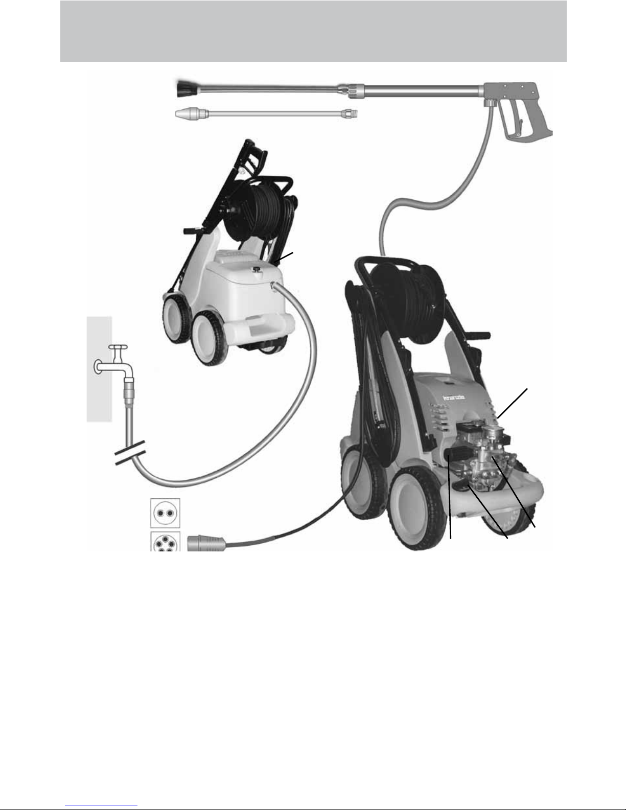
6 Detergent valve
7 High pressure hose
8 Spray gun
9 Interchangeable lance with at jet
nozzle and nozzle protection
10 Interchangeable lance with dirtkiller
1 Water inlet connection with lter
2 Cover for water tank
3 High pressure pump
4 Press. gauge with glycerin lling
5 Unloader valve - safety valve
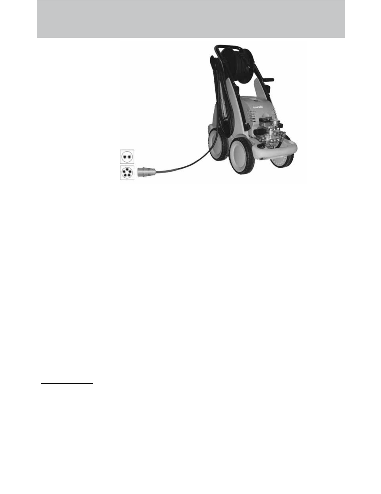
Connection principle
The KRÄNZLE quadro 599 TST , 799 TST and 899 TST- high pressure cleaners are
mobile machines with hose drum and 20m industrial hose.
The connection principle can be seen from the illustration.
Components
Description
10
7
6
4
quadro 599
230V/50Hz
5
quadro 799
quadro 899
400V/50Hz
Page 5
Water system
The water must be lead to the high pressure cleaner under pressure (2 – 8 bar
ad-mission pressure). A oat valve regulates the water inlet. Then, the water is
sucked by the high pressure pump from the water tank and supplied to the lance
under the set pressure. The high pressure jet is formed by the nozzle at the end of
the lance.
Detergent and caring system
The high pressure pump can also suck a detergent/caring
agent and mix it with the high pressure jet. The additive
is sucked through the pump and brought in with the set
pressure.
Insert the detergent hose into the detergent container and
open the detergent valve (6). The detergent must have
the ph-value 7-9 neutral.
The detergent discharges with the water at the high pressure nozzle.
Only open the dosing valve, if the chemistry sieve is placed in a liquid.
Sucked air leads to destruction of the pump seals !!!
The rules concerning the environment, refuse and ground water protection must be complied with!
Description
5
Lance with spray gun
The machine can only be operated when the safety trigger is squeezed.
When the lever is squeezed, the spray gun opens. The liquid is then pumped
to the nozzle. The spray pressure increases and quickly reaches the selected
operating pressure. For the deairing of the system open and close the gun quickly
a few times. When the trigger is released, the trigger gun closes and any further
spraying of liquid from the lance is stopped and the pressure gauge must show 0
bar.
The increase in pressure when the trigger gun is closed causes the unloader
valve-safety valve to open. The pump remains switched on and continues to pump
liquid through the pump at reduced pressure. When the spray gun is opened, the
unloader valve - safety valve closes and the pump ressumes spraying from the
lance with the selected operating pressure.
The spray gun is a safety device. Repairs should only be performed by qualied persons. Should replacement parts be required, use only components authorized by the manufacturer.
6
Page 6

High pressure hose and spraying device
The high pressure hose and spraying device supplied with the machine are made
of high grade material. They are also optimized for the machine and marked as
required by the appropriate regulations.
If replacement parts are required, only such parts that are authorized
by the manufacturer and which bear the markings required by the
appropriate regulations may be used. The high pressure hose and
spraying device must be connected in a pressure-tight manner.
The high pressure hose may not be driven over, pulled excessively or
twisted. Hose lines are wear parts. Guarantee is accepted only for ma-
nufacturing errors, not for external damages.
High pressure hose lines and spraying equipment must not be repaired, but replaced by a new hose or spraying equipment.
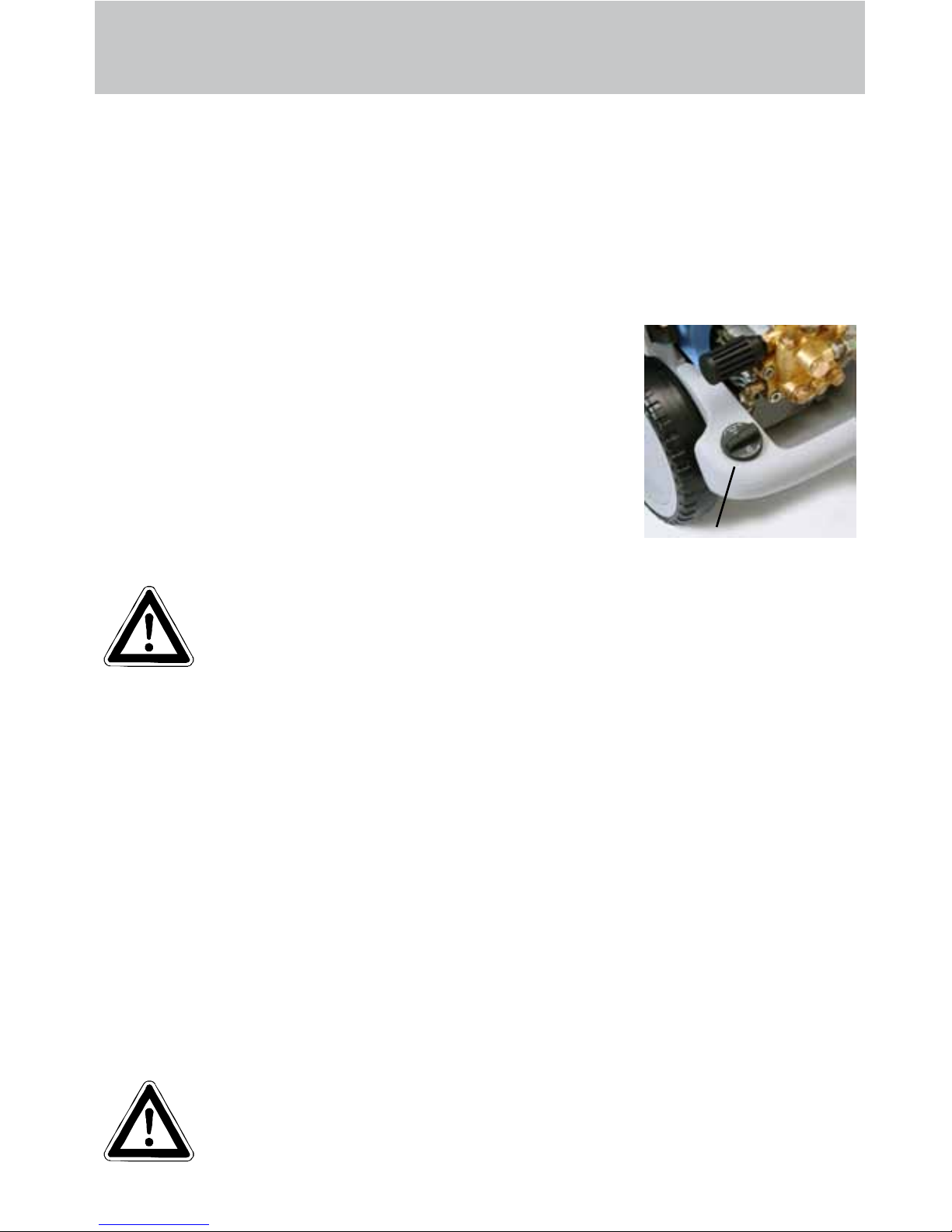
Unloader valve - safety valve
The unloader valve - safety valve protects the machine from a build up of excess
pressure, and is designed not to permit an excess pressure to be selected for
operation. The limit nut on the handle is sealed with a spray coating.
The operating pressure and spray rate can be steplessly adjusted by
turning the handle.
Replacements, repairs, new adjustments and sealing should only be
performed by qualied persons.
Take care that all screw connections are pressure-tight. A leakage of gun,
high-pressure hose or hose drum has to be repaired at once. Leakages
lead to an increased wear and to the destruction of the delayed motor
cut-out.
Operator’s task:
Prior to each usage of this liquid spraying device, the operator is obliged
to check if all safety relevant parts are in perfect working condition. (e.g.
safty valves, high-pressure hose, cables and connections, spraying
devices, etc. )
Description
6
Page 7
7
Description
Delayed motor cut-out
Frequent, work-necessitated switching on and off of motors on
machines of this size puts a heavy load on the power network and
causes increased wear on internal electrical parts. Therefore the
motor of the new KRANZLE device only switches off 30 seconds after closing the
gun and then goes to stand still. By opening the gun, the device is started again.
Safety cut-out
If the device is accidentally not turned off after use or the pistol is not used for 20
minutes, the device automatically goes into the safety state via deactivating. By
operating the main switch again, the device is activated again.
Replacements and inspection work should only be performed by qualied persons when the machine is disconnected from the power supply,
i.e. the plug pulled out from the electrical socket.
Setting up
Location
Neither set up and operate the machine in rooms where there is a risk
of re or explosion nor put it into puddles. Do not use the machine under
water. The device must not stand in the spray area of the high pressure jet.
CAUTION !
Never suck in liquid containing solvents such as paint thinners, petrol, oil or similar
liquid matter. Pay attention to the instructions of the manufacturers of
the cleaning agents. The seals in the machine are not resistant to solvents! The spray of solvents is inammable, explosive and poisonous.
CAUTION !
When running your high pressure cleaner with hot water of 60° C raised tempera-
tures occur. Do not touch the machine without safety gloves!
Page 8
Description
quadro 799
400V/50Hz
Electrical connection
The machine is supplied with an electrical power cord with plug.
The mains plug must be tted to a standard grounded socket with a 30mA residual current operated device. The socket must be protected with a 16A delay action
fuse on the mains side.
KRÄNZLE quadro 599 TST = 230 Volt / 50 Hz
KRÄNZLE quadro 799 TST = 400 Volt / 50 Hz
KRÄNZLE quadro 899 TST = 400 Volt / 50 Hz phase-sequence not signicant)
When using an extension cable, this must have a grounded lead which is properly
connected to the socket. The conductors in the extension cable must have a minimum cross section of 1.5 mm². Plug connections must be of a spray-proof design
and may not be located on a wet oor.
CAUTION !
The use of extension cables which are too long may lead to malfunctions and start
up difculty. If the extension cable is longer than 10m it must have a min. cross
section of 2.5mm².
When using a cable drum, always keep the cable wound as far as possible.
8
quadro 599
230V/50Hz
Page 9
9
Description
Brief operating instructions:
1. Connect high pressure hose with spray gun.
2. Connect to suitable water supply.
3. Connect current
(quadro 599: 230V/50Hz AC;
quadro 799 , 899: 400V/50Hz three-phase current).
4. Switch on machine and start cleaning.
5. After having completed the cleaning process, put main switch in zero position and by opening the gun, reduce the pressure in the high pressure
hose.
Then, the high pressure hose can be rolled up.
- Only use clean water ! Protect from frost !
CAUTION !
Please pay attention to the regulations of your waterworks company.
Because of the water tank, the device can be connected to any drinking water line
without worries.
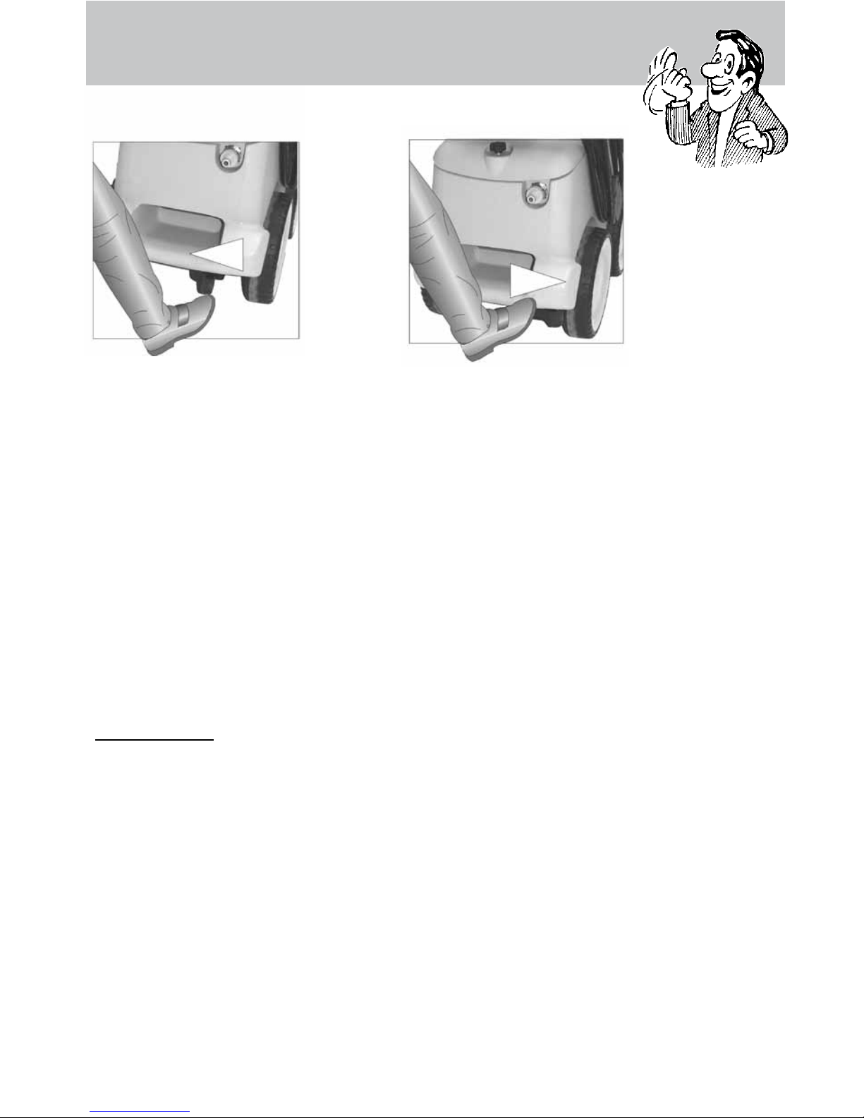
Brake applied
Brake not applied
Brake
Page 10
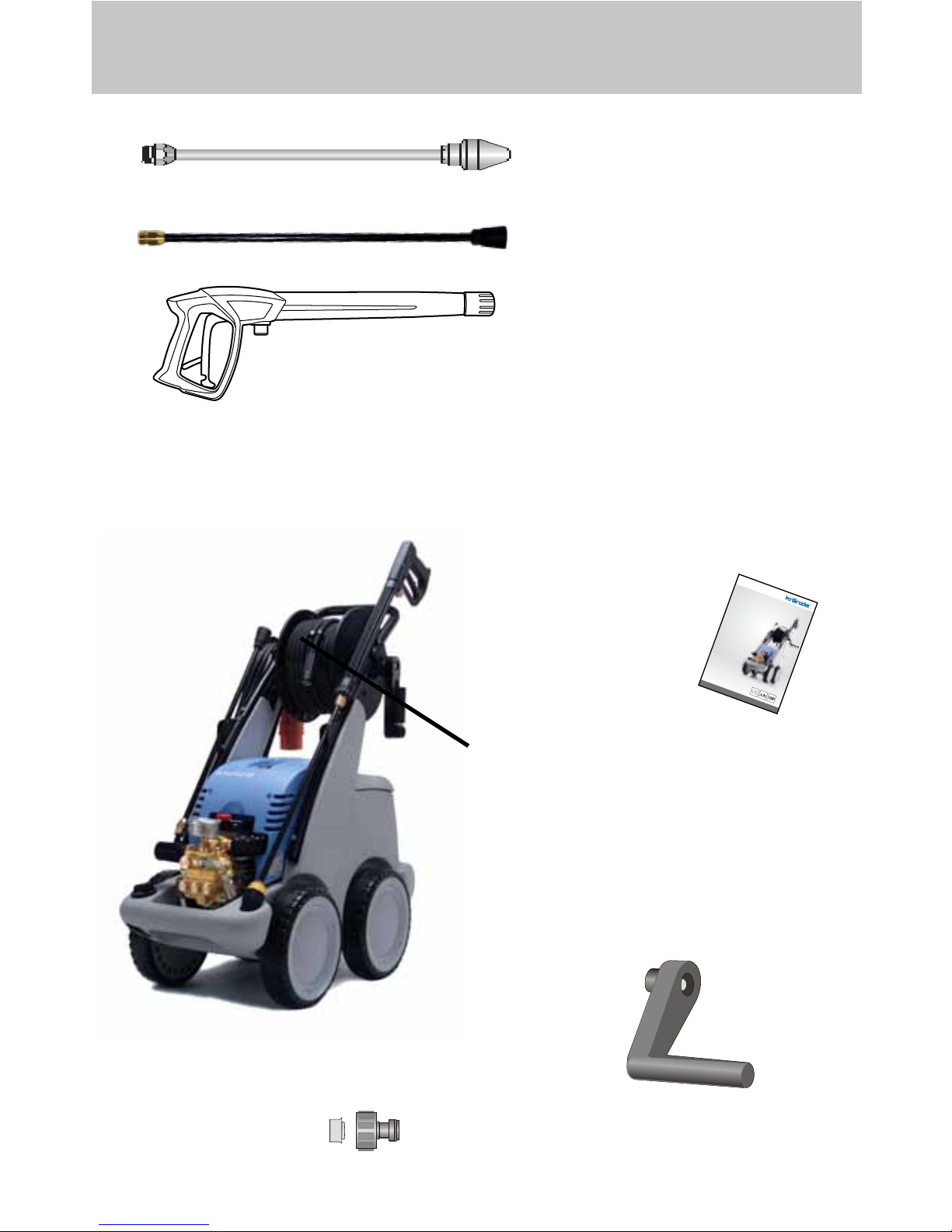
This is what you’ve purchased:
1. Dirtkiller
Lance with nozzle
protection and high
pressure nozzle
Flat jet 25°
2. Spray gun M2000
with insulated handle
and screw connection
3. KRÄNZLE - High pressure cleaners
quadro 599 TST and quadro 799 TST with hose drum and
20 m HP hose NW 6 with steel reinforcement
4. Operating manual
5. HP hose 20 m NW 6
with hose drum
7. Plug-in connection of
water inlet parts and lter
(already installed)
6. Collapsible crank
for hose drum
(already installed)
10
www.kraenzle.com
Page 11
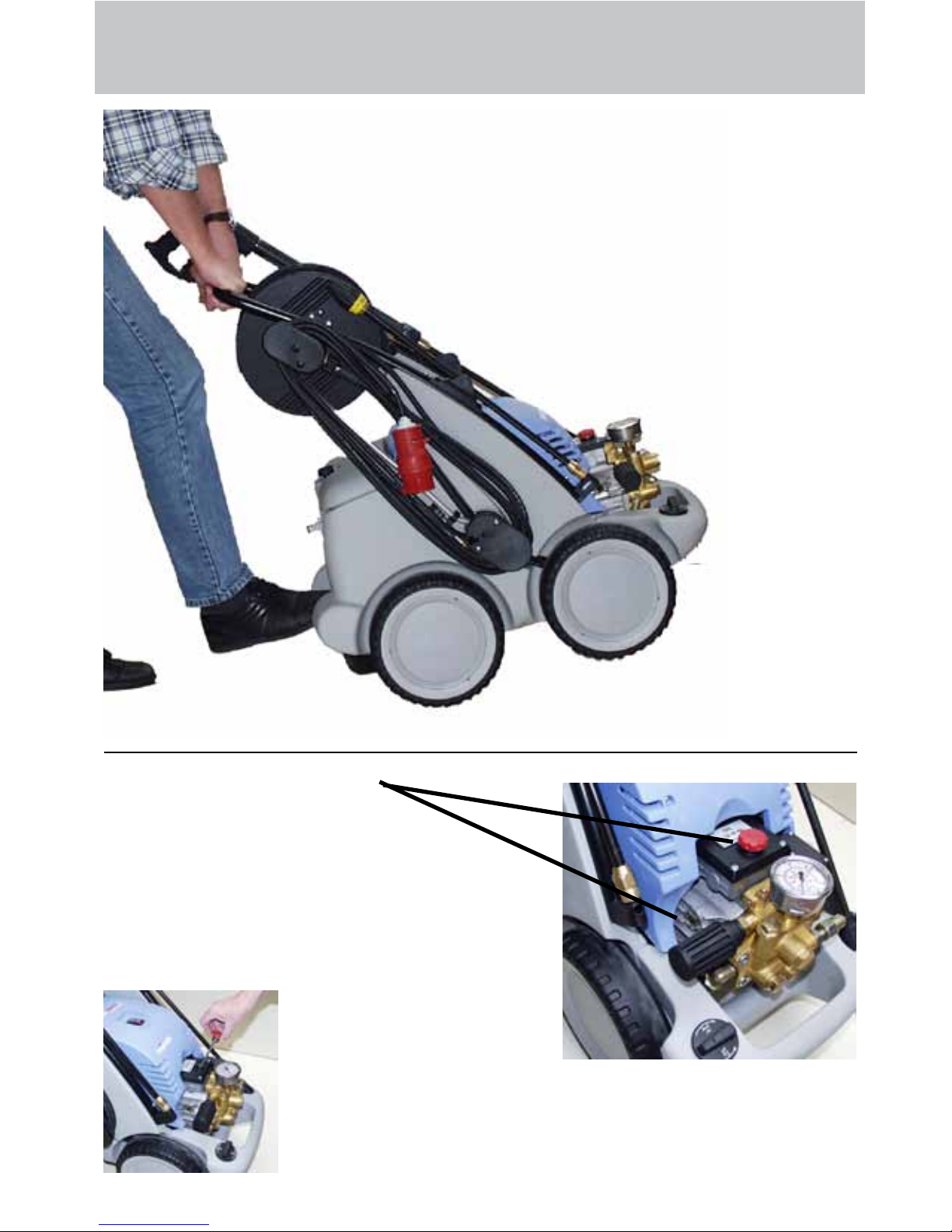
Preparation for use
11
To control the high pressure cleaner
put
1. the foot against the tilt bases and
2. then pull the device towards you.
1. Check oil level.
There are two
possibilities for checking the
oil level of the pump:
a) Oil must be visible in the viewing
window
b) The oil level must be between the two
markings on the oil dip stick.
To check the oil level, loosen
the oil cover screw and take
out the oil dip stick. The oil
level must be between the two markings.
a
b
Page 12
Preparation for use
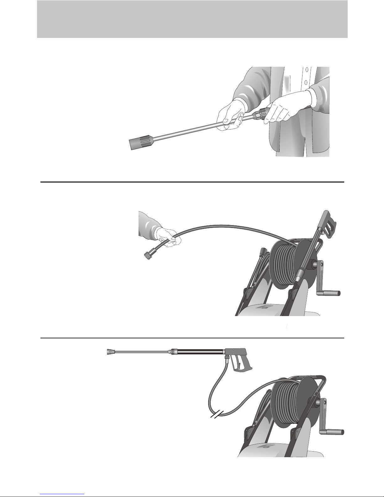
4. Connection of high pressure
hose from device to lance.
2. Connect the high pressure lance
or dirtkiller to the spray gun.
12
3. Unroll hose without kinks and connect with handgun and pump. Use
max. 20 m HP hose.
Page 13
Preparation for use
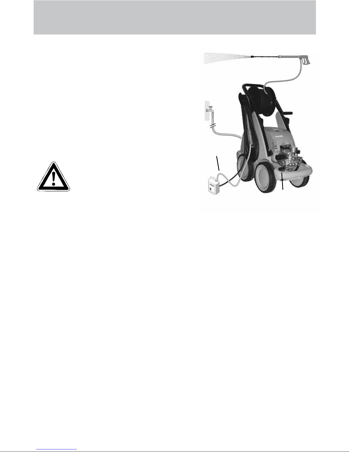
5. The machine must be connected to the water line
with cold water or up to 60° C warm water (see
page 2).
The hose cross section must be at least 3/4" =
16 mm (free passage). Filter 1 must always be
clean.
Please make sure that the lter is clean before
using your high pressure cleaner.
CAUTION !
When running your high pressure cleaner with hot water of 60° C raised temperatures occur.
Do not touch the pump without safety gloves!
13
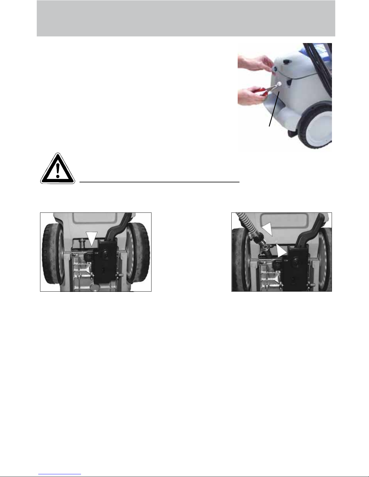
Undercarriage Undercarriage
External suction
If water is to be sukked from an external
container for the high
pressure cleaner, the
connection hose between the high pressure pump and the water
tank must be screwed
off and the suction
hose must be connec-
ted via a double nipple
3/4“ (Order no.: 46.004) to the connection hose.
Make sure that the water is clean. Use the Kränzle suction hose with suction lter.
(Order no. 15.038 3)
Maximum suction height 2.5 m, maximum water temperature for direct suction: 60°C
(see technical data on page 2)
1
Page 14
14
To shut down the pump
1. Switch off the machine. Device switch to „0“ position.
2. Cut off the water supply.
3. Open the spray gun briey until the pressure is released.
4. Apply the safety catch on the spray gun.
5. Remove the water hose and spray gun.
6. Pull the plug from the socket.
7. Winter: store the pump in rooms above 0°C.
8. Clean the water lter.
To shut down the pump:
Frost protection
Normally after operation, there is still some water in the device. Thus, you must take
special measures to protect the device from frost.
- Completely drain the device
For this purpose, separate the device from the water supply. Then, turn on the main
switch and open the gun. Now, the pump presses the remaining water from the water
tank and the pump. However, do not allow the device to operate without water for longer than one minute.
- Fill the device with antifreeze agent
If the device is not operated for longer periods, especially over the winter, you should
pump an antifreeze agent through the device. For this purpose, ll the anti-freeze
agent into the water box and turn on the device. Wait with opened gun, until the agent
comes from the nozzle.
However, the best way to protect the device from frost is
to store it at a frost-free location.
When using detergents
Put chemistry sieve number 5 into the detergent container. Open the detergent valve (6),
then the detergent is sucked in. When closing
the detergent valve, the chemistry supply is
automatically closed. Allow detergent to act and
then wash off. (see page 5).
Note that you must always comply with the
instructions provided by the manufacturer
of the detergent (e.g. safety clothing) and the
water protection regulations!
Only open the valve, if the chemistry
sieve is in a liquid. Sucked in air leads
to the destruction of the pump seals !!!
Damages to the pump caused by sucked in
air are not covered by the guarantee.
5
6
Page 15
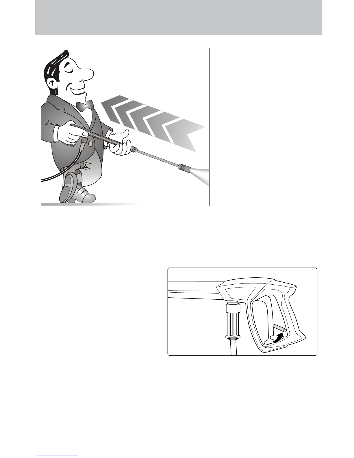
Safety notes
As to the recoil see notice on page 2!
Apply the safety catch on the spray
gun after each use, in order to pre-
vent unintentional spraying!
15
Page 16

This is prohibited !
Do not damage the
power cable or repair it
incorrectly!
Never direct the water
jet at people or animals
!
Never pull the high pressure hose if it has formed
kinks or “nooses”!
Never pull the hose over
sharp edges !
16
Page 17

This is prohibited !
Never allow children to
use the high pressure
cleaner !
Never direct the water
jet at the machine itself !
Never direct the water
jet at a power socket !
17
Page 18

Additional accessories for ...
(on demand)
Rotary scrubbing brush
Order No. 41.050 1
Drain and pipe cleaning
hose
10 m - Order No. 41.058.1
15 m - Order No. 41.058
Environmental, refuse disposal and water protection
regulations must be observed when using the accessories!
18
Guarantee
The guarantee is only valid for material and manufacturing errors.
Wearing does not fall within this gurantee.
The instructions in our operating manual must be complied with. The operating
instructions form part of the guarantee. The Guarantee is void if other parts are
used than genuine Kränzle accessory parts or genuine Kränzle spare parts.
For high-pressure cleaners sold to the user the guarantee period is 24 month.
For high-pressure cleaners sold for industrial use the guarantee period is 12
month. In the case of a guarantee please contact your dealer or authorized
seller delivering accessories and your purchase receipt. You can nd them in the
internet under www.kraenzle.com.
The guarantee is also void if the machine is used with exceeding the temperature
and speed limits, a voltage below the required rating, with less than the required
amount of water or with dirty water. Pressure gauge, nozzle, valves, sleeves, high
pressure hose and spray equipment are wear parts and are not covered by the
warranty.
Page 19

... further combination possibilities
Car cleaning, glass, caravan, boat etc.: rotary washing brush with 40 cm extension and
ST 30 nipple M22 x 1.5
Cleaning pipes, channels and drains: pipe
cleaning hose with KN nozzle and ST 30
nipple M22 x 1.5
Rotary point sprayer for extreme soiling:
Turbokiller with 40 cm extension and ST 30
nipple M22 x 1.5
Cleaning cars and all smooth surfaces:
brush with ST 30 nipple M22 x 1.5
19
Page 20

20
Small repairs ...
The nozzle is blocked!
No water but the gauge shows full pressure !
Rinse the hose through
rst.
You should now have
a powerful
stream of
water,
but if you
only get a few
drops of water
from the
lance
remove the lance and clean
the nozzle.
Using the at spray lance you
only have to clean the front
nozzle.
Straighten a paper
clip and clean the nozzle.
Insert pointed object
into the hole and pull
the cap back!
Check visually whether the
nozzle is clean.
Now it works as well
as before.
Page 21

21
do it yourself !
Nozzle dirty or sticky!
Pressure gauge does not show full pressure
Water comes out in spurts.
If you do not use the high-pressure cleaner for some time the valves can stick
The high-pressure hose vibrates
Straighten a
paper clip...
When a valve is
blocked,
or the high
pressure
hose vibra-
tes!
Open the valve
with a socket
wrench...
and remove the
valve screw, the
valve and the
o-ring.
Replace the rubber o-ring.
and remove the
dirt from the valve
- the valve inside
must be closed.
Retighten the
valve screw
...and repeat
on all 6
valves.
Now it works
as well as
before!
the gauge
shows little
pressure or
no pressure
at all
Page 22

22
Complete Assembly
Page 23

23
quadro 599 TST - 899 TST
Spare parts list KRÄNZLE quadro 599 TST - 899 TST
Complete assembly
No Description Qty. Ord.-No No Description Qty. Ord.-No
Motor-Pumpe ohne Elektrik
1.1 für quadro 599 TST 1 46.085 1
1.2 für quadro 799 TST 1 46.085 2
1.3 für quadro 899 TST 1 46.085 3
Motor-Pumpe mit Elektrik
1.4 für quadro 599 TST 1 46.086 1
1.5 für quadro 799 TST 1 46.086 2
1.6 für quadro 899 TST 1 46.086 3
2 Schubbügel 1 46.033
3 Schraube M6x35 DIN6912 8 46.024
4 Scheibe 6,4 DIN125 4 50.189
5 Wasserkasten 1 46.026
6 Lanzenablage 1 46.028
7 Kabelaufwicklung unten 1 42.611
8 Zugentlastung 1 43.431
9 Blechschraube 3,5 x 12 2 40.290
10 Kunststoffschraube 5,0 x 30 2 41.412
11 Lanzenständer 1 46.021
12 Rohrstopfen dm25 1 46.022
13 Scheibe 8,4 DIN125 4 50.186
14 Kabelaufwicklung oben 1 42.612
15 Gummipuffer 30 x 20 4 46.023
16 Rad d250 4 46.010
17 Federstecker 4 40.115 1
18 Radkappe 4 46.011
19.1 Frontplatte quadro 599 TST 1 46.014 1
19.2 Frontplatte quadro 799 TST 1 46.014 2
19.3 Frontplatte quadro 899 TST 1 46.014 3
20 Lanzenhalter 2 42.610
21 Blechschraube 3,9x13 DIN7981 5 41.078
22 Fahrgestell incl. Pos. 50, 51, 52 1 46.001
24 Elastic-Stop-Mutter M8 4 41.410
25 Netzanschlusskabel 5,75m 1 41.092
Wechselstrom (quadro 599 TST)
25.1 Netzanschlusskabel8m 1 44.036
Drehstrom(quadro799/899TST)
26 Schlauchtrommelkpl. 1 46.081
27 Chemiesaugschlauch(Gewebe)mitFilter1 42.621
28 Gewebeschlauch0,4m 1 42.622
29 Schlauchklemme8-12 2 44.0545
30 GehäuseWaschmittelventil 1 44.145
31 O-Ring5x1,5(Viton) 1 44.150
32 O-Ring28,24x2,62 1 44.149
33 RegulierkolbenChemieventil 1 44.147
34 Edelstahlfeder1,8x15x15 1 44.148
35 DeckelfürChemieventil 1 44.146
36 Blechschraube3,5x16 3 44.161
37 Blechschraube3,5x19 2 44.162
38 DrehgriffChemieventilmitBlendkappe 1 44.151
39.1 LanzemitFlachstrahldüsefür599TST 1 12.394-M20035
39.2 LanzemitFlachstrahldüsefür799TST 1 12.394-M20045
39.3 LanzemitFlachstrahldüsefür899TST 1 12.394-D2506
40 PistoleM2000 1 12.480
41.1 Schmutz-Killer035beiquadro599TST 1 46.150
41.2 Schmutz-Killer045beiquadro799TST 1 46.1501
41.3 Schmutz-Killer06beiquadro899TST 1 46.1502
42 Hochdruckschlauch20mNW6 1 43.4161
quadro599,799TST
42.1 Hochdruckschlauch15mNW8 1 44.879
quadro899TST
43 O-Ring13x2,6 2 13.272
44 Verbindungsschlauch 1 46.032
47 RückschlagventilfürChemiesaugschl. 1 44.240
48 ChemieventilKpl.Pos.30-37 1 44.052
49 Wasserfilter 1 42.633
50 AufnahmeBremse 1 46.042
51 Schraube5,0x20 3 43.018
52 Scheibe19mm 6 43.830
Page 24

24
Water inlet and brake
Page 25

25
No Description Qty. Ord.-No
Spare parts list KRÄNZLE quadro 599 TST - 899 TST
Water inlet and brake
quadro 599 TST - 899 TST
Bremse kpl. 46.080
bestehend aus: Pos. 6-14
1 Revisionsdeckel 1 46.027
2 Dichtung für Revisionsdeckel 1 46.030
3 Sterngriffschraube M6 1 46.031
4 Schwimmerventil 1 46.250
5 Mutter R3/4“ 1 46.258
6 Kunststoffschraube 5x14 1 43.426
7 Scheibe 5,3 DIN9021 1 50.152
8 Zugfeder 1 46.020
9 Deckel Bremse 1 46.016
10 Hebel Bremse 1 46.017
11 Sternschraube M8 1 50.168
12 Schraube 3,5x14 4 44.525
13 Schelle 2 43.431
14 Bolzen für Bremse 1 46.018
15 Dichtung für Schwimmerventil 1 46.261
16 Bundschraube 1 46.019
17 Einströmschlauch 1 46.043
Page 26

26
Pump motor
Page 27

223232323
27
quadro 599 TST
No Description Qty. Ord.-No
Spare parts list KRÄNZLE quadro 599 TST
Pump motor
Switch box compl. items 23 - 43 46.082
Motor compl. without switch items 1 - 22 24.085
1 Stator BG100 2,3kW 230V / 50Hz 1 40.720
2 A-Lager Flansch 1 40.700
3 Rotor BG100 230V / 50Hz 1 40.703 1
4 Lüfterrad BG100 1 40.702
5 Lüfterhaube BG100 1 40.701
7 Flachdichtung 1 43.030
10 Schrägkugellager 7306 1 40.704
11 Öldichtung 35 x 47 x 7 1 40.080
12 Passfeder 8 x 7 x 28 1 40.459
13 Kugellager 6206 - 2Z 1 40.538
14 Innensechskantschraube M 6 x 30 4 43.037
18 Innensechskantschraube M 5 x 12 4 41.019 4
19 Schraube M 4 x 12 4 41.489
20 Schelle für Lüfterrad BG100-112 1 40.535
22 Erdungsschraube kpl. 1 43.038
23 Schalter 14,5 A Amazonas 1 41.111 6
24 Kunststoffschraube 4,0 x 16 4 43.417
26 Kunststoffschraube 5,0 x 25 6 41.414
28 Kunststoffschraube 3,5 x 20 2 43.415
29 Lüsterklemme 5-pol. 1 43.326 1
30 Schütz 230V 50/60 Hz 1 46.005
31 Schaltkasten Unterteil 1 46.012
32 Schaltkasten Deckel 1 46.013
33 Steuerplatine Abschaltverz. 230V / 50Hz 1 42.564
34 Klemmrahmen mit Schalterabdichtung 1 43.453
36 Blechschraube 3,5 x 14 2 44.525
37 PG 16-Verschraubung 1 41.419 1
38 Dichtung für Schaltkastendeckel 1 46.013 1
39 Gegenmutter für PG9-Verschraubung 2 41.087 1
40 Gegenmutter für PG16-Verschraubung 1 44.119
41 PG 9 - Verschraubung 1 42.541
42 Kondensator 60µF 1 41.148
43 PG 9 – Verschraubung reduziert 1 41.087
Page 28

28
Pump motor
Page 29

quadro 899 TST
No Description Qty. Ord.-No
Spare parts list KRÄNZLE quadro899 TST
Pump motor
29
Switch box compl. items 23 - 42 46.083
Motor compl. without switch items 1 - 22 24.080
1 Stator 100 4,0kW 400V / 50Hz 1 40.710
2 A-Lager Flansch 1 40.700
3 Rotor 100 400V / 50Hz 1 40.703
4 Lüfterrad BG100 1 40.702
5 Lüfterhaube BG 100 1 40.701
7 Flachdichtung 1 43.030
10 Schrägkugellager 7306 1 40.704
11 Öldichtung 35 x 47 x 7 1 40.080
12 Passfeder 8 x 7 x 28 1 40.459
13 Kugellager 6206 - 2Z 1 40.538
14 Innensechskantschraube M 6 x 30 4 43.037
18 Innensechskantschraube M 5 x 12 4 41.019 4
19 Schraube M 4 x 12 4 41.489
20 Schelle für Lüfterrad BG100-112 1 40.535
22 Erdungsschraube kpl. 1 43.038
23 Schalter 14,5 A Amazonas 1 41.111 6
24 Kunststoffschraube 4,0 x 16 4 43.417
26 Kunststoffschraube 5,0 x 25 6 41.414
28 Kunststoffschraube 3,5 x 20 2 43.415
29 Lüsterklemme 5-pol. 1 43.326 1
30 Schütz 100-C12KN10 3x400V 50/60 Hz 1 46.005 1
31 Schaltkasten Unterteil 1 46.012
32 Schaltkasten Deckel 1 46.013
33 Steuerplatine Abschaltverz. 1 42.503
34 Klemmrahmen mit Schalterabdichtung 1 43.453
36 Blechschraube 3,5 x 14 2 44.525
37 PG 16-Verschraubung 1 41.419 1
38 Dichtung für Schaltkastendeckel 1 42.525
39 Gegenmutter für PG9-Verschraubung 1 41.087 1
40 Gegenmutter für PG16-Verschraubung 1 44.119
41 PG 9 - Verschraubung 1 42.541
42 Überstromauslöser 3-polig 9 – 12,5 A 1 42.641 2
Page 30

30
Transmission unit
Page 31

29
31
quadro 599 TST
No Description Qty. Ord.-No
Spare parts list KRÄNZLE quadro 599 TST
Pump transmission unit for AM-pump
Transmission unit AM compl. 46.087 1-7,66
with ball bearing for quadro 599
consisting of: Items 1-24
1 Ölgehäuse mit Öldichtungen 1 40.452
4 Innensechskantschraube M 8 x 25 6 40.053
5 Sicherungsscheibe 6 40.054
6 Flachdichtung 1 40.511
7 Öldichtung 18 x 28 x 7 3 41.031
9 Axial-Rillenkugellager AM 1 40.462
11 Taumelscheibe 7,66° quadro 599 1 40.460-7,66
12 Plungerfeder 3 40.506
13 Federdruckscheibe 3 40.454
14 Plunger 18mm (AM-Pumpe) 3 40.455
15 Sprengring 3 41.035
16 O-Ring 14 x 2 1 43.445
18 Flachdichtung 1 41.019 3
19 Deckel 1 41.023 1
20 Innensechskantschraube M 5 x 12 4 41.019 4
21 Ölmessstab (AM-Pumpe) 1 40.463
23 O-Ring 13,94 x 2,62 1 42.167
24 Ölablassstopfen R 3/8“ 1 42.019
Page 32

32
Transmission unit
Page 33

33
quadro 799 TST
No Description Qty. Ord.-No
Spare parts list KRÄNZLE quadro 799 TST
Pump transmission unit for AM-pump
Antrieb AM kpl. mit Rollenlager 46.087 2-10,8
für quadro 799
bestehend aus: Pos. 1-24
Antrieb AM kpl. mit Rollenlager 46.087 2-12,5
für quadro 899
bestehend aus: Pos. 1-24
1 Ölgehäuse mit Öldichtungen 1 40.452
4 Innensechskantschraube M 8 x 25 6 40.053
5 Sicherungsscheibe 6 40.054
6 Flachdichtung 1 40.511
7 Öldichtung 18 x 28 x 7 3 41.031
8 Wellenscheibe 1 40.043
9 Axial-Rollenkäg 1 40.040
10 AS-Scheibe 1 40.041
11 Taumelscheibe 10,8° quadro 799 1 40.460-10,8
11.1 Taumelscheibe 12,5° quadro 899 1 40.460-12,5
12 Plungerfeder 3 40.506
13 Federdruckscheibe 3 40.454
14 Plunger 18mm (AM-Pumpe) 3 40.455
15 Sprengring 3 41.035
16 O-Ring 14 x 2 2 43.445
18 Flachdichtung 1 41.019 3
19 Deckel 1 41.023 1
20 Innensechskantschraube M 5 x 12 4 41.019 4
21 Ölmessstab (AM-Pumpe) 1 40.463
23 O-Ring 13,94 x 2,62 1 42.167
24 Ölablassstopfen R 3/8“ 1 42.019
Page 34

34
Unloader valve and pressure switch
Page 35

35
quadro 599 TST - 899 TST
Spare parts list KRÄNZLE quadro 599 TST - 899 TST
Unloader valve and pressure switch
No Description Qty. Ord.-No
No Description Qty. Ord.-No
Steuerkolben kpl. mit Handrad 40.490
Pos. 5, 14-25
Rep.-Satz Druckschaltermechanik 15.009 3
1x Pos. 51, 1x Pos. 52, 1x Pos. 53,
3x Pos. 54, 1x Pos. 55, 1x Pos. 56,
1x Pos. 57, 1x Pos. 58, 1x Pos. 59
Druckschalter kpl. Pos. 54 - 70 41.300 5
55 Stützscheibe 2 15.015 1
56 Edelstahlfeder 1 15.016
57 Steuerstößel 1 15.010 2
58 Parbaks 7 mm 1 15.013
59 Stopfen M 10 x 1 (durchgebohrt) 1 13.385 1
60 Gehäuse Elektroschalter 1 15.007
61 Gummimanschette PG 9 1 15.020
62 Scheibe PG 9 1 15.021
63 Verschraubung PG 9 1 15.022
64 PVC-Kabel 2x 1,0 mm² 1 42.505
65 Blechschruabe 2,8 x 16 6 15.024
66 Deckel Elektroschalter 1 15.008
67 O-Ring 44 x 2,5 1 15.023
68 Mikroschalter 1 15.018
69 Zylinderschraube M 4 x 20 2 15.025
70 Sechskant - Mutter M 4 2 15.026
72 Druckfeder 1 x 8,6 x 30 1 40.520
5 O-Ring 16 x 2 1 13.150
5.1 O-Ring 13,94 x 2,62 1 42.167
8 O-Ring 11 x 1,44 1 12.256
9 Edelstahlsitz 1 14.118
10 Sicherungsring 1 13.147
11 Edelstahlkugel 1 13.148
12 Edelstahlfeder 1 14.119
13 Verschlussschraube 1 14.113
14 Steuerkolben 1 14.134
15 Parbaks 16 mm 1 13.159
16 Parbaks 8 mm 1 14.123
17 Spanstift 1 14.148
18 Kolbenführung spezial 1 42.105
19 Kontermutter M 8 x 1 2 14.144
20 Ventilfeder schwarz 1 14.125
21 Federdruckscheibe 1 14.126
22 Nadellager 1 14.146
23 Handrad AM-Pumpe 1 40.457
24 Kappe Handrad AM-Pumpe 1 40.458
25 Elastic-Stop-Mutter M 8 x 1 1 14.152
26 Manometer 0-250 Bar 1 15.039
27 Aluminium-Dichtring 2 13.275
50 O-Ring 3,3 x 2,4 1 12.136
51 Führungsteil Steuerstößel 1 15.009 1
52 O-Ring 13 x 2,6 1 15.017
53 O-Ring 14 x 2 1 43.445
54 Parbaks 4 mm 2 12.136 2
Page 36

36
Valve housing
Page 37

37
Spare parts list KRÄNZLE quadro 599 TST -899 TST
Valve housing for integrated AM-pump
No Description Qty. Ord.-No
No Description Qty. Ord.-No
quadro 599 TST - 899 TST
Ventilgehäuse kpl. ohne Manometer 46.084
bestehend aus: Pos. 1 - 8; Pos. 11 - 39
Reperatur - Sätze:
Rep.-Satz Manschetten 18 mm 41.049 1
bestehend aus je 3x Pos. 13; 6x Pos. 14;
3x Pos. 15; 3x Pos. 23; 3x Pos. 18
Rep.-Satz Ventile für APG-Pmpe 41.748 1
bestehend aus je 6x Pos. 2; 6x Pos. 3;
6x Pos. 4
1 Ventilgehäuse AM-Pumpe 1 40.451
2 O-Ring 15 x 2 6 41.716
3 Ventile (grün) 6 41.715 1
4 O-Ring 16 x 2 6 13.150
5 Ventilstopfen 5 41.714
5.1 Ventilstopfen mit R1/4” IG 1 42.102
7 Innensechskantschraube M10 x 35 4 42.509 1
8 Schlauchnippel R1/4“ x 8 1 46.038
9 Schlauchschelle 7 - 10 1 44.054
10 Chemiesaugschlauch mit Filter 1 46.038 1
11 Dichtring 1 40.019
12 Stopfen 3/8” 1 40.018
13 Manschette 18 x 26 x 4/2 3 41.013
14 Backring 18 mm 6 41.014
15 O-Ring 3 40.026
16 Leckagering 18 mm 3 41.066
18 Gewebemanschette 18 x 26 x 5,5/3 3 41.013 1
20 Zwischenring 18 mm 3 41.015 2
23 Druckring 3 41.018
24 Usit-Ring 1 12.387
25 O-Ring 11 x 1,5 1 12.256
26 Edelstahlsitz Ø 7 1 14.118
27 Sprengring 1 13.147
27 Aluminium-Dichtring 4 13.275
28 Ausgangsteil Pumpe R1/4“ x 12 1 46.039
29 Kupferring 1 42.104
30 Dichtstopfen R1/4“ mit Bund 1 42.103
31 Dichtstopfen M10 x 1 1 43.043
32 Dichtstopfen M 8 x 1 2 13.158
33 Ausgangsteil 1 40.522
34 Edelstahlkugel Ø10 1 12.122
35 Rückschlagfeder „K“ 1 14.120 1
36 Stopfen R1/4“ 1 13.387
37 O-Ring 18 x 2 1 43.446
38 Ermetowinkel 12L x 12L 1 42.630
39 Ermetowinkel R3/8“ x 12L 1 44.092
Page 38

38
Hose drum
Page 39

39
quadro 599 TST - 899 TST
No Description Qty. Ord.-No
Spare parts list KRÄNZLE quadro 599 TST - 899 TST
Hose drum
No Description Qty. Ord.-No
Ventilgehäuse kpl. ohne Manometer 46.084
bestehend aus: Pos. 1 - 8; Pos. 11 - 39
Reperatur - Sätze:
Rep.-Satz Manschetten 18 mm 41.049 1
bestehend aus je 3x Pos. 13; 6x Pos. 14;
3x Pos. 15; 3x Pos. 23; 3x Pos. 18
Rep.-Satz Ventile für APG-Pmpe 41.748 1
bestehend aus je 6x Pos. 2; 6x Pos. 3;
6x Pos. 4
23 Drehgelenk 1 40.167
25 Distanzring 1 40.316
27 O-Ring 6,86 x 1,78 1 40.585
28 Anschlussstück 1 40.308
33 O-Ring 6 x 1,5 1 13.386
34 Stopfen M 10 x 1 1 13.385
40 Überwurfmutter 1 13.276 2
42 O-Ring 9,3 x 2,4 4 13.273
44 Verbindungsschlauch 1 46.037
45 Hochdruckschlauch NW6 20 m 1 43.416 1
quadro 599, 799 TST
45.1 Hochdruckschlauch NW8 15 m 1 44.879
quadro 899 TST
1 Seitenschale 2 46.201
3 Trommelteil 2 46.202
5 Innensechskantschraube M 4 x 25 4 40.313
6 Lagerklotz mit Bremse 1 40.306 1
7 Lagerklotz links 1 40.305 1
8 Klemmstück 2 40.307 1
9 Kunststoffschraube 5,0 x 20 12 43.018
10 Antriebswelle 1 46.204
11 Welle Wasserführung 1 46.203
12 Elastic-Stop-Mutter M 4 4 40.111
13 Handkurbel 1 40.320 0
14 Verriegelungsbolzen 1 40.312
15 Scheibe MS 16 x 24 x 2 1 40.181
16 Wellensicherungsring 22 mm 2 40.117
17 Wellensicherungsring 16 mm 1 40.182
20 Parbaks 16 mm 2 13.159
21 Sicherungsscheibe 6 DIN6799 1 40.315
22 Schraube M 5 x 10 1 43.021
Page 40

40
Lance
No Description Qty. Ord.-No
1 Pistolenschale re+li 1 12.450
2 Schraube 3,5 x 14 10 44.525
18 O-Ring 9,3 x 2,4 1 13.273
51 Düsenschutz 1 26.002 1
52 Rohr 500 mm; bds. M12x1 1 41.527 1
53 ST 30 Nippel M 22 x 1,5 / M12x1 m. ISK 1 13.363
54 Flachstrahldüse 20035 (quadro 599) 1 M20035
54.1 Flachstrahldüse 20045 (quadro 799) 1 M20045
54.2 Flachstrahldüse 2506 (quadro 899) 1 D2506
55 Aluminium-Dichtring 8,3x11,3x2 2 13.275 1
Lanze kpl. mit HD-Düse M20035 12.394-M20035
Lanze kpl. mit HD-Düse M20045 12.394-M20045
Lanze kpl. mit HD-Düse D2506 12.394-D2506
Page 41

41
Dirtkiller
No Description Qty. Ord.-No
1 Sprühkörper 1 41.520
2 O-Ring 6,88 x 1,68 1 41.521
3 Düsensitz 1 41.522
4 Düse 035 (quadro 599) 1 41.523 1
4.1 Düse 045 (quadro 799) 1 41.523
4.1 Düse 06 (quadro 899) 1 41.523 5
5 Stabilisator 1 41.524
6 O-Ring 1 40.016 1
7 Sprühstopfen R1/4“ IG 1 41.526 1
8 Rohr 600 mm lang; bds. R1/4“ 1 12.385 2
9 Nippel M22x1,5 x R1/4“ IG 1 13.370
11 Kappe vorn für Schmutzkiller 1 41.528 1
12 Kappe hinten für Schmutzkiller 035 1 41.540 4
12.1 Kappe hinten für Schmutzkiller 045 1 41.540 2
12.2 Kappe hinten für Schmutzkiller 06 1 41.542 2
Rep.-Satz Schmutzkiller 035 41.097 0
Rep.-Satz Schmutzkiller 045 41.097
Rep.-Satz Schmutzkiller 06 41.096 2
bestehend aus je 1x 2; 3; 4; 5
Schmutzkiller 035 mit Lanze 600mm 46.150
Schmutzkiller 045 mit Lanze 600mm 46.150 1
Schmutzkiller 06 mit Lanze 600mm 46.150 2
Page 42

42
Wiring diagram
Wiring diagram for KRÄNZLE quadro 599 TST
230 Volt / 50 Hz
On-Off switch
with 14,5 Ampere
overload protection
Inlet line via
3x 1,5mm²
230 V / 50 Hz
Pump motor
230 V / 50 Hz
Pressure switch
Control plate with
transformer 230 V / 50
Hz
Contactor
Page 43

43
Wiring diagram
Wiring diagram for KRÄNZLE quadro 799 TST
400 Volt / 50 Hz
On-Off switch
with 8,5 Ampere
overload protection
Inlet line via
CEE 4x1,5mm²
400 V / 50 Hz
Pump motor
3x 400 V / 50 Hz
Pressure switch
Control plate with
transformer 400 V / 50
Hz
Contactor
Page 44

44
Inspections
The machine must be inspected according to the “Guidelines for Liquid Spray Devices” at
least once every 12 months by a qualied person, to ensure that continued safe operation
is guarateed.
The results of the inspection are to be recorded in writing.
This may be done in any form. (see pages 46-47)
Accident prevention
The machine is designed for accidents to be impossible if used correctly.
The operator is to be notied of the risk of injury from hot machine parts and the high
pressure water jet. The “Guidelines for Liquid Spray Devices” must be complied with. (see
pages 15 - 17).
Check the oil level at the oil dip stick prior to each use (see also page 11).
(Ensure horizontal position!)
Oil change:
The rst oil change should be carried out
after approximately 50 operating hours,
then every year or after 1000 operating
hours. If the oil turns grey or white, you must
change the oil of your high pressure pump
in any case. Open the oil discharge screw
at the bottom of the device over a collection resevoir. Ensure a horizontal position
to drain the oil completely. The oil is to be
caught in the reservoir and disposed of in
an approved manner.
New oil: 0,8 l
Motor oil: Castrol 10 W-60 SAE halfsynthetic oil
General rules
Oil discharge screw
Page 45

I. Kränzle GmbH
Elpke 97 . 33605 Bielefeld
Hochdruckreiniger
High-pressure-cleaners
Nettoyeurs À Haute Pression
We hereby declare,
that the high-pressure models:
(techn. documentation available from):
Nominal ow
comply with the following guidelines
and specications and their amendments for high-pressure cleaners:
Sound power level measured:
guaranteed:
Applied conformity evaluation
procedures:
Applied specications and
standards:
EC declaration of conformity
Bielefeld, den 12.19.2012
Kränzle quadro 599 - 899 TST
Manfred Bauer, Fa. Josef Kränzle
Rudolf-Diesel-Str. 20, 89257 Illertissen
K quadro 599 TST: 600 l/h
K quadro 799 TST: 780 l/h
K quadro 899 TST: 900 l/h
Machine guideline 2006/42/EEC
Specication for electromagnetic
compatibility 2004/108/EEC
Outdoor noise directive 2005/88/EC,
Art. 13, High-pressure water jet machines
Appendix 3, part B, chapter 27
86 dB (A)
88 dB (A)
annex V, noise directive 2005/88/EC
EN 60 335-2-79 :2009
EN 55 014-1 :2006
EN 55 014-2 / A2:2008
EN 61 000-3-2 :2006
EN 61 000-3-3 :2008
R
Kränzle Josef
(Managing Director)
Page 46

46
Inspection report for HP cleaners
Type plate (on hand)
Operating manual (on hand)
Protective covering, -device
Pressure line (tightness)
Pressure gauge (function)
Float valve (tightness)
Spraying device (marking)
HP-hose / connector (damage, marking)
Safety valve opens at 10 % / 20 % exceeding of operating pr.
Power cable (damage)
Protective conductor (connected)
On / Off switch
Used chemicals
Allowed chemicals
High-prsure nozzle
Operating pressure..................bar
Switch off pressure................bar
Conductor reist. not exceeded / value
Insulation
Leakage current
Gun locked
The appliance was checked by an expert according to the Guidelines for Liquid
Spray Equipment, the defects found have been rectied so that the Labour Safety can be
conrmed.
The appliance was checked by an expert according to the Guidelines for Liquid
Spray Equipment. The Labour Safety cannot be conrmed unless the defects found are
rectied by repair or replacement of the faulty parts
The next retest according to the Guidelines for Liquid Spray Equipment has to be carried
out by: Month Year
Place, date Signature
HP clea n e r s fo r indust r i a l us e have to be ch e c k ed by an expert every 12 mo nths!
Ins p ection re p ort o n an nually ca rried ou t La bour Sa f e ty Insp e c tion (U V V ) accor d i ng
to t he Gui delines f or Liq uid Sp ray E quipment. (This inspectio n she et serves a s proof
for the completion of the retest and must be kept carefully!)
Kränzle test seals: Order no. UVV200106
Scope of inspection o.k. yes no repaired
Inspection data determined value set value
Inspection result (tick)
Owner:
Address:
Type:
Serial no.:
Rep. order no.:
Page 47

47
Inspection report for HP cleaners
Type plate (on hand)
Operating manual (on hand)
Protective covering, -device
Pressure line (tightness)
Pressure gauge (function)
Float valve (tightness)
Spraying device (marking)
HP-hose / connector (damage, marking)
Safety valve opens at 10 % / 20 % exceeding of operating pr.
Power cable (damage)
Protective conductor (connected)
On / Off switch
Used chemicals
Allowed chemicals
High-prsure nozzle
Operating pressure..................bar
Switch off pressure................bar
Conductor reist. not exceeded / value
Insulation
Leakage current
Gun locked
The appliance was checked by an expert according to the Guidelines for Liquid
Spray Equipment, the defects found have been rectied so that the Labour Safety can be
conrmed.
The appliance was checked by an expert according to the Guidelines for Liquid
Spray Equipment. The Labour Safety cannot be conrmed unless the defects found are
rectied by repair or replacement of the faulty parts
The next retest according to the Guidelines for Liquid Spray Equipment has to be carried
out by: Month Year
Place, date Signature
HP clea n e r s f o r indu s t r i a l u s e h a v e t o be checked by an e xpert every 12 m o nths!
Ins p ection r e port on a n nually c a rried o u t Labou r S afety I n specti o n (UVV) a c cordin g
to t he Gui del ines for Liquid S pra y Equipment. ( Thi s inspection s hee t serves as pr oof
for the completion of the retest and must be kept carefully!)
Kränzle test seals: Order no. UVV200106
Scope of inspection o.k. yes no repaired
Inspection data determined value set value
Inspection result (tick)
Owner:
Address:
Type:
Serial no.:
Rep. order no.:
Page 48

Made
in
Germany
www.kraenzle.com
I . K r ä n z l e G m b H
E l p k e 9 7
D - 3 3 6 0 5 B i e l e f e l d
R e p ri n t o n l y a ll o we d w it h t h e a ut h o r is a ti o n o f K rä nz l e .
A s d a te o f 0 2 /2 2/ 2 01 3
S u b j e c t t o t e c h n i c a l m o d i f i c a t i o n s . O r d e r n o . 3 0 . 6 0 0 1
 Loading...