

Page 1
Operating manual
H i g h - p r e s s u r e c l e a n e r
Read and conform safety instructions prior to putting into operation !
- GB -
Page 2
Description
2
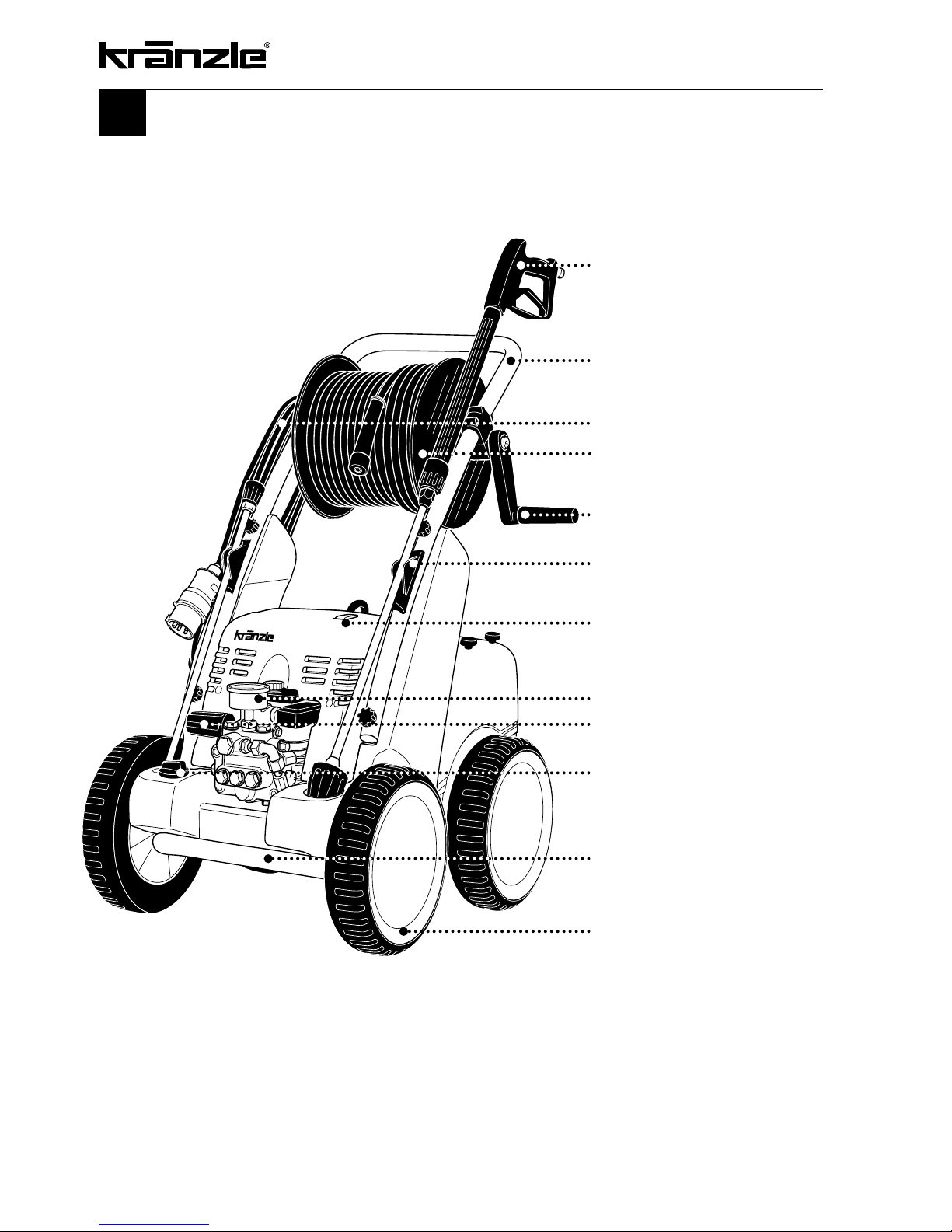
Kränzle quadro 1500 TS T
Spray gun with safety cut-out
Ergonomically shaped handlebar
made of stainless steel, detachable
Cable reel with 7.5 m cable
Hose drum with 20 m steel fabric
high-pressure hose
(TS T-models only)
Hand crank, tiltable
Receptacle for gun
with spray lance during breaks
On/Off switch with signal lamp
Large stainless steel
manometer
Continuously adjustable
pressure control
Detergent valve,
continuously adjustable
Shock absorbing buffers,
front and rear
Large wheels with wide
solid rubber tyres
Page 3

Description of appliance ............................................................................. 2
Contents .............................................................................................. 3
Technical data ............................................................................................ 4
Overview 'This is what you have purchased' ................................................ 6
General rules ............................................................................................. 7
Safety precautions ...................................................................................... 8
That's what you have to observe ............................................................ 11
Kränzle- technology ................................................................................ 13
Water and cleaning system ...... ..............................................13
Lance and spray gun ............................................................. 13
Pressure control valve – safety valve ..................................... 13
Delayed motor cut-out ........................................................... 14
High pressure hose and spray device .................................... 14
Safety cut-out ....................................................................... 14
Putting into operation............................................................................. 15
Connection to water mains .................................................... 15
Direct suction ........................................................................ 20
When using detergents .......................................................... 21
To shut down the pump – frost protection .................................................. 22
Small repairs – do it yourself .................................................................... 23
EC – Declaration of Conformity ................................................................. 28
Guarantee ............................................................................................ 29
Accessories for high-pressure cleaners ..................................................... 30
Spare parts list ....................................................................................... 32
Complete assembly ............................................................... 32
Brake.................................................................................... 34
Water inlet ............................................................................ 35
Pump motor .......................................................................... 36
Pump transmission unit ......................................................... 38
Unloader valve and pressure switch ....................................... 40
Valve housing ....................................................................... 42
Hose drum ............................................................................ 44
Gun 'Starlet' with lance ......................................................... 46
Turbokiller with lance ............................................................ 47
Wiring diagramme .................................................................................... 48
Inspections – inspection reports ................................................................ 49
3
Contents
Page
Page 4
4
Technical data
Operating pressure, continuously adjustable 30 - 140 bar
Admissible overpressure 160 bar
Water output at nominal pressure *1 25 l/min
Nozzle size, flat jet nozzle 2511
Nozzle size, Turbokiller lance 11
Volume water tank 16 l
Max. inlet water temperature
into water tank 60 °C
Max. temperature
for direct suction *2 60 °C
Suction height for direct suction 2.5 m
Hose drum yes
Steel fabric high-pressure hose NW8 20 m
Detergent sucking yes
Connected load
400 V, 12 A, 50 Hz
Motor speed 1.400 r.p.m
Power input P 1 - 7.5 kW
Power output P 2 - 5.5 kW
Weight incl. accessories
(empty water tank) 89 kg
Dimensions including handle L x W x H in mm 770 x 570 x 990
Sound level acc. to DIN 45 635 89 dB (A)
Sound level with Dirtkiller 91 dB (A)
Acoustic power LWA 91 dB (A)
Recoil at lance approx. 24 N
Vibration at lance 2.2 m/s
2
*1 Min. water quantity to be supplied to the high pressure cleaner! (2-8 bar admission pressure)
*2 Direct suction is possible through by-passing of water tank. (see page 13)
Permissible tolerance for figures ± 5 % acc. to VDMA uniform sheet 24411
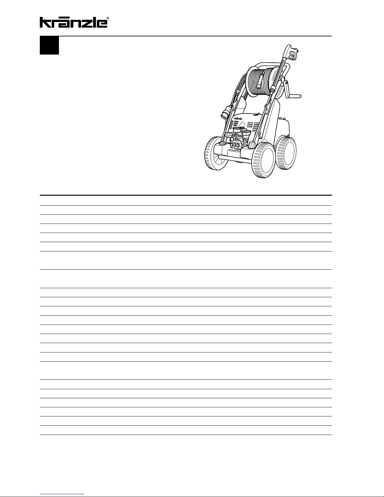
quadro 1500 TST
Page 5
5
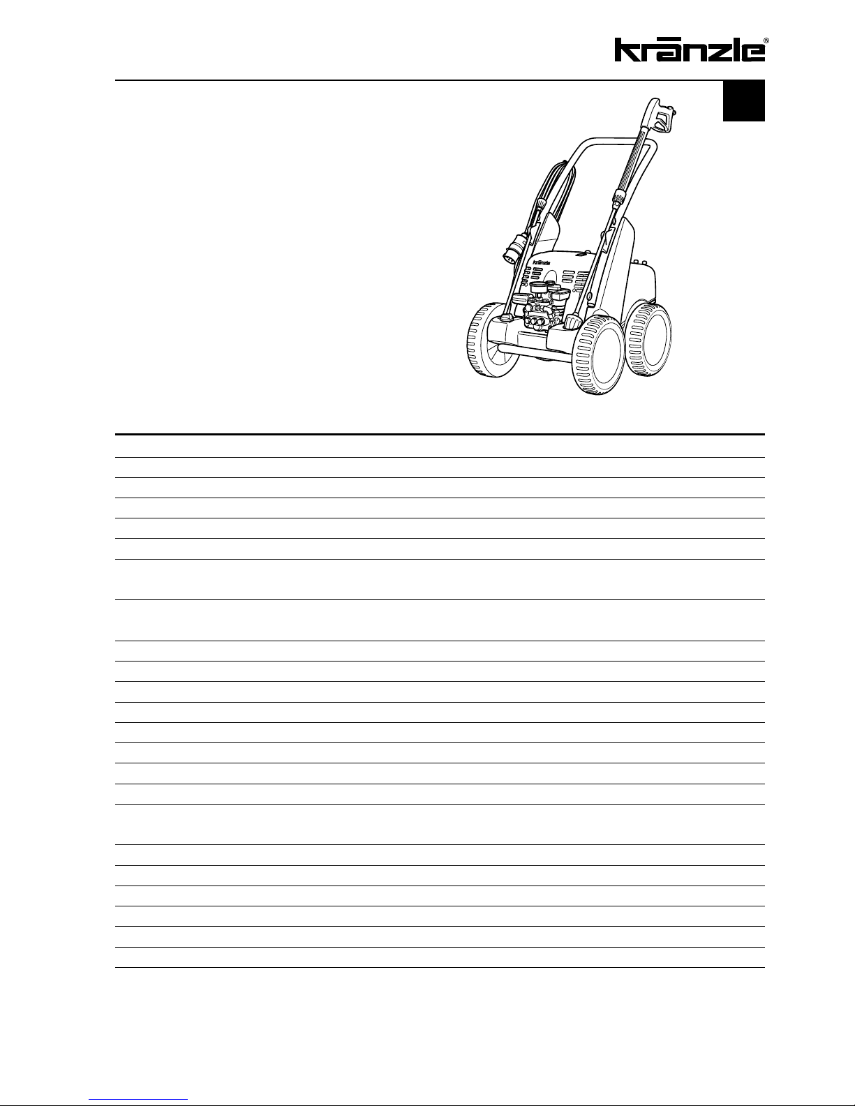
Operating pressure, continuously adjustable 30 - 140 bar
Admissible overpressure 160 bar
Water output at nominal pressure *1 25 l/min
Nozzle size, flat jet nozzle 2510
Nozzle size, Turbokiller lance 10
Volume water tank 16 l
Max. inlet water temperature
into water tank 60 °C
Max. temperature
for direct suction *2 60 °C
Suction height for direct suction 2.5 m
Hose drum no
Steel fabric high-pressure hose NW8 10 m
Detergent sucking yes
Connected load
400 V, 12 A, 50 Hz
Motor speed 1.400 r.p.m
Power input P 1 - 7.5 kW
Power output P 2 - 5.5 kW
Weight incl. accessories
(empty water tank) 82 kg
Dimensions including handle L x W x H in mm 770 x 570 x 990
Sound level acc. to DIN 45 635 89 dB (A)
Sound level with Dirtkiller 91 dB (A)
Acoustic power LWA 91 dB (A)
Recoil at lance approx. 24 N
Vibration at lance 2.2 m/s
2
*1 Min. water quantity to be supplied to the high pressure cleaner! (2-8 bar admission pressure)
*2 Direct suction is possible through by-passing of water tank. (see page 13)
Permissible tolerance for figures ± 5 % acc. to VDMA uniform sheet 24411
quadro 1500 TS
Technical data
Page 6
6
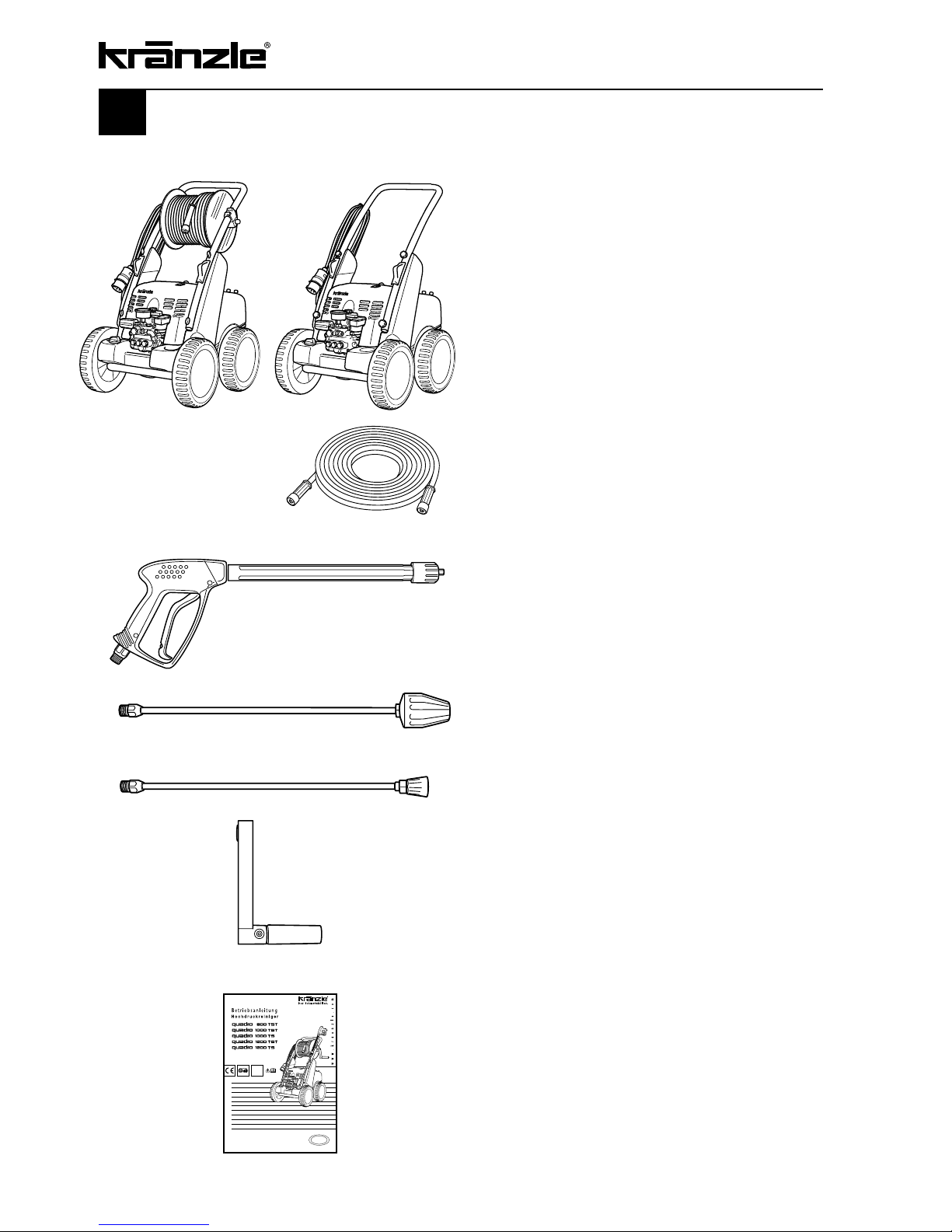
3.
Turbokiller lance
with TS appliances as special accessory
This is what you have purchased
1.
Kränzle high-pressure cleaner
quadro 1500 TS T
with hose drum and 20 m steel fabric
high-pressure hose NW 8
or
Kränzle high-pressure cleaner
quadro 1500 TS T without
hose drum and 10 m steel fabric
high-pressure hose NW 8
2.
Safety spray gun ‘Starlet’ with insulated
handle and screw connection
4.
Washing lance with new Kränzle knife jet
nozzle
5.
Tiltable handle with fixing screw for hose
drum
6.
Operating manual
Page 7

7
General rules
Range of application
Use machines for cleaning tasks with high-pressure water jet and detergents or with
high-pressure water jet without detergents only.
Inspections
The machine must be inspected according to the “Guidelines for Liquid Spray Devices”
at least once every 12 months by a qualified person, to ensure that continued safe
operation is guaranteed. The results of the inspection are to be recorded in writing. This
may be done in any form. For inspection reports see pages 49 - 51.
High-pressure cleaners used for commercial purposes have
to be checked by a qualified person at least every 12 months!
Accident prevention
The machine is designed for accidents to be impossible if used correctly. The operator is
to be notified of the risk of injury from hot machine parts and the high pressure water jet.
The “Guidelines for Liquid Spray Devices” must be complied with (see pages 8 and 9).
Oil change:
Oil leakage: If oil leaks out, contact nearest customer service (dealer) immediately. (Environmental damages, transmission damages, loss of guarantee). In case of increased
humidity or fluctuations in temperature the formation of
condensed water is possible; if the oil turns grey, it has to
be changed immediately.
Oil drain screw
(View of appliance from below)
The first oil change should be carried out
after approximately 50 operating hours,
then every year or after 1000 operating
hours. Open the oil drain screw at the bottom of the device over a collection resevoir. The oil is to be caught in the reservoir
and disposed of in an approved manner.
New oil: 1,0 l - Motor oil
10/W-60 SAE semi-synthetic oil
Page 8
8
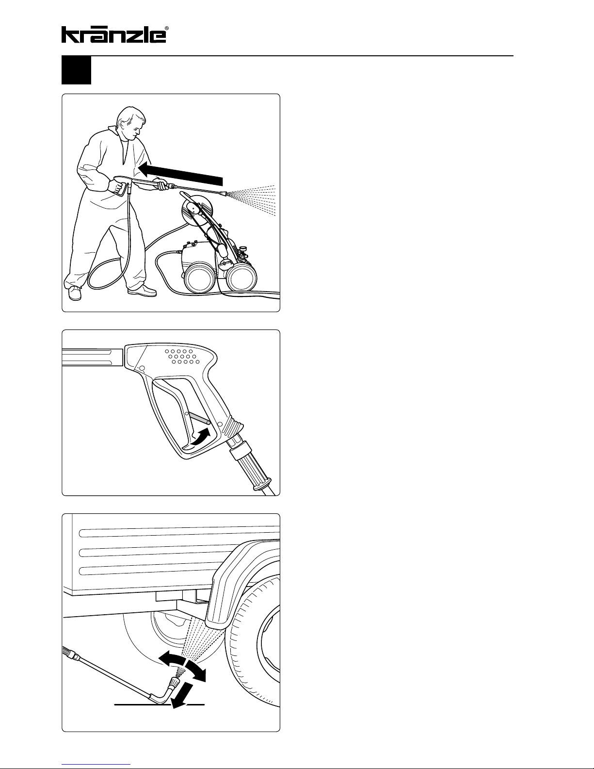
Safety precautions
Always bear in mind that during cleaning
tasks with a high-pressure water jet a
significant recoil at the lance arises (see
technical data on page 4 and 5).
Apply the safety catch on the spray gun
after each use, in order to prevent
unintentional spraying!
Always aim the underbody lance! Bear in
mind when using a curved or angled
spraying lance that there is a significant
amount of torque in the recoil!
Page 9
9
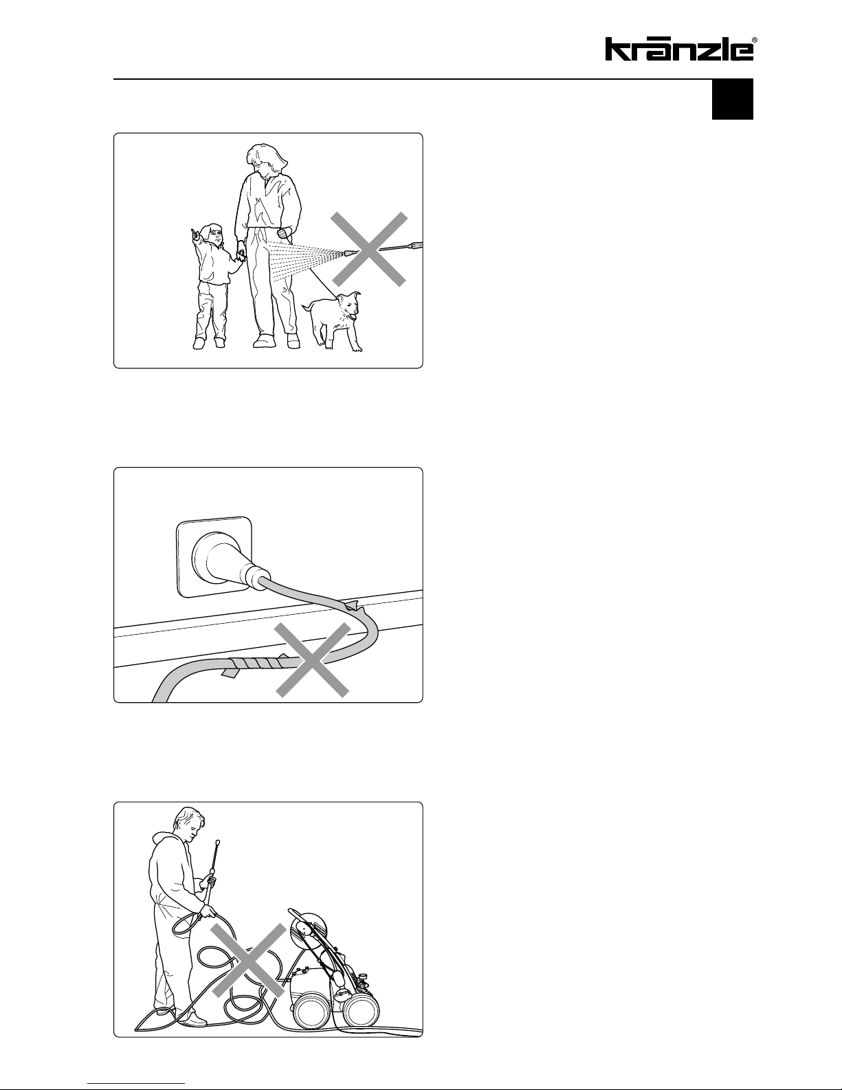
Safety precautions – This is prohibited!
Never direct the water jet at people
or animals!
Only use power cables which are in
perfect working order!
Do not damage the power cable or
repair it incorrectly!
Never pull the high pressure hose
if it has formed kinks or “nooses”!
Never pull the hose over sharp
edges!
Page 10
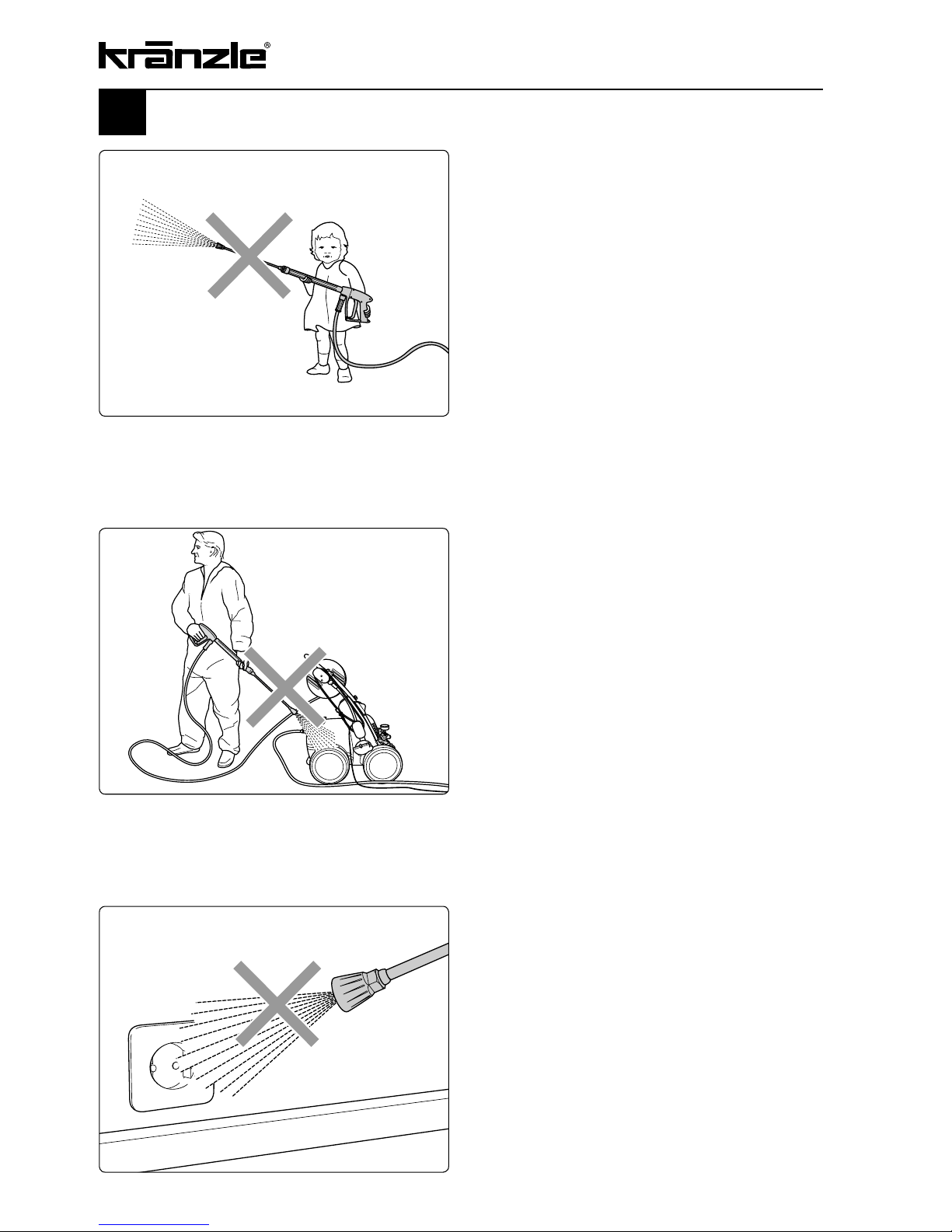
10
Never allow children to use the
high pressure cleaner!
Never direct the water jet at the
machine itself!
The machine may not be placed within
reach of the water jet spray mist!
Never direct the water jet at a power
socket!
Safety precautions – This is prohibited!
Page 11
11
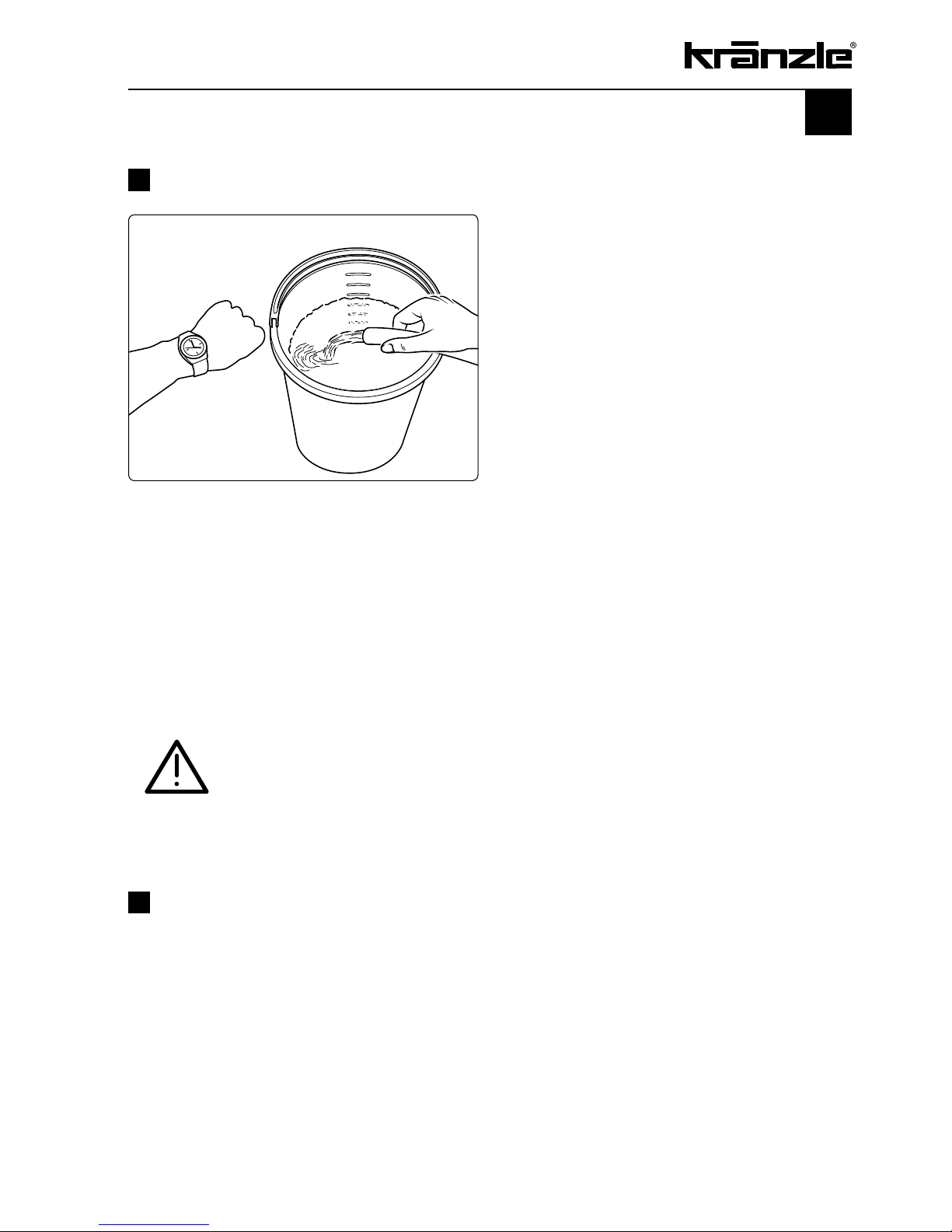
That's what you have to observe
!
Lack of water
Lack of water occurs more often than you
probably believe. The more powerful a
high-cleaner is the greater is the danger
that a lack of water occurs. If there is only
an insufficient amount of water available,
cavitation arises inside the pump, which is
normally noticed too late or even not at all.
The pump will be destroyed!
Please check the available quantity of
water by filling a bucket with litre scale for
half a minute
.
Connection to water supply
Please pay attention to the regulations of your waterworks company! In accordance with
DIN EN 61770, the machine may not be directly connected to the public drinking water
supply lines. A brief connection however is permissible according to DVGW (German
Association for Gas and Water Affairs) if a tube ventilator with check valve (Kränzle
Order-No. 41.016 4) is built into the water supply. Also indirect connection to the public
drinking water supply lines is permissible by way of free emission in accordance with
EN 61 770; e.g. by using a reservoir with a float valve. Direct connection to a non-drinking
water supply line is permissible.
If the metered quantity of water is too small, you have to use a
different water connection, guaranteeing the necessary output.
Lack of water leads to an accelerated wear of the joints
(no guarantee).
The following minimum quantity of water
is necessary for a safe and problem-free
operation of the high-pressure cleaner
:
Kränzle quadro 1500 TS T 25 l/min = 12.5 l/1/2 min
Page 12
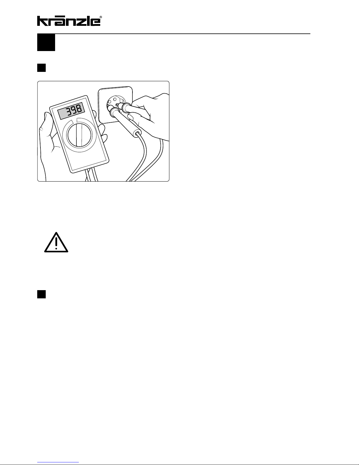
Insufficient current intensity
If there are too many collectors in your
proximity connected to the network at the
same time, the available voltage and the
current intensity may decline. Consequent ly the motor of the high-pressure cleaner
does not start or even blows.
The power supply may also be insufficient
if the power cable is too long or too thin. If
extension cables are too long, this may
lead to a voltage drop causing malfunct ions or start-up difficulties.
Connected load: 400 V, 12 A, 50 Hz
Electrical connection
The machine is supplied with an electrical power cable with plug. The mains plug must
be fitted to a standard grounded socket with a 30mA residual current operated device.
The socket must be protected with a 16A delay action fuse on the mains side.
Kränzle
quadros: 400 Volt, 50 Hz
. When using an extension cable, this must have an earthed
lead which is properly connected to the socket. The conductors in the extension cable
must have a minimum cross section of 1.5 mm². Plug connections must be of a sprayproof design, and may not be located on a wet floor. With extension cables of more than
10 m the minimum cross section must be 2.5 mm! When using a cable drum, always
keep the cable wound as far as possible.
Check the line fusing and have the voltage and the available
current intensity checked by an expert in case of uncertainty.
12
That's what you have to observe
!
Page 13

13
Kränzle technology
Water and Cleaning System
The water must be lead to the high pressure cleaner under pressure (2 – 8 bar admission pressure). A float valve regulates the water inlet. Then, the water is sucked by the
high pressure pump from the water tank and supplied to the lance under the set pressure. The high pressure jet is formed by the nozzle at the end of the lance.
Bypassing the water tank enables the cleaner to suck in water directly from a pressureless container. (see page 20)
Environmental, refuse disposal and water protection
regulations must be observed!
Lance with trigger gun
The machine can only be operated when the safety trigger is squeezed. When the lever
is squeezed, the spray gun opens. The liquid is then pumped to the nozzle. The spray
pressure increases and quickly reaches the selected operating pressure. When the
trigger is released, the gun closes and any further spraying of liquid from the lance is
stopped. The pressure gauge must show 0 bar.
The increase in pressure when the spray gun is closed causes the pressure control
valve-safety valve to open. The motor is switched off by the pressure switch. When the
spray gun is opened, the pressure control valve - safety valve closes, the motor is
started and the pump resumes pressure spraying from the lance with the selected
operating pressure.
The spray gun is a safety device. Repairs should only be
performed by qualified persons. Should replacement
parts be required, use only components authorized by the
manufacturer.
Pressure control valve - safety valve
The pressure control valve - safety valve protects the machine from a build up of
excess pressure, and is designed not to permit an excess pressure to be selected for
operation. The limit nut on the handle is sealed with a spray coating. The operating
pressure and spray rate can be steplessly adjusted by turning the handle
.
Replacements, repairs, new adjustments and sealing
should only be performed by qualified persons.
Page 14
14
Delayed motor cut-out
Frequent, work-necessitated switching on and off of motors on machines of this size puts
a heavy load on the power network and causes increased wear on internal electrical
parts. Therefore the motor of the Kränzle quadro device only switches off 30 seconds
after closing the gun and then goes to stand still. By opening the gun, the device is
started again.
Replacements and inspection work should only be
performed by qualified persons when the machine is
disconnected from the power supply, i.e. with plug pulled
out from the electrical socket.
High pressure hose and spray device
The high pressure hose and spraying device supplied with the machine are made of high
grade material, they are also optimized for the machine and marked as required by the
appropriate regulations.
If replacement parts are required, only such parts that are
authorized by the manufacturer and which bear the markings required by the appropriate regulations may be
used. The high pressure hose and spray device must be
connected in a pressure-tight manner. The high pressure
hose may not be driven over, pulled excessively, or
twisted. The hose may under no circumstances be pulled
over sharp edges.
Hoses are wearing parts. The guarantee only covers
defects of fabrication no external damages whatsoever.
Defective high-pressure hoses and spraying devices may
not be repaired. They always have to be replaced.
Safety cut-out
If the device is accidentally not turned off after use or the pistol is not used for 20 minutes, the device automatically cuts off from the power supply system (safety state). By
operating the main switch once more, the device is activated again.
Page 15
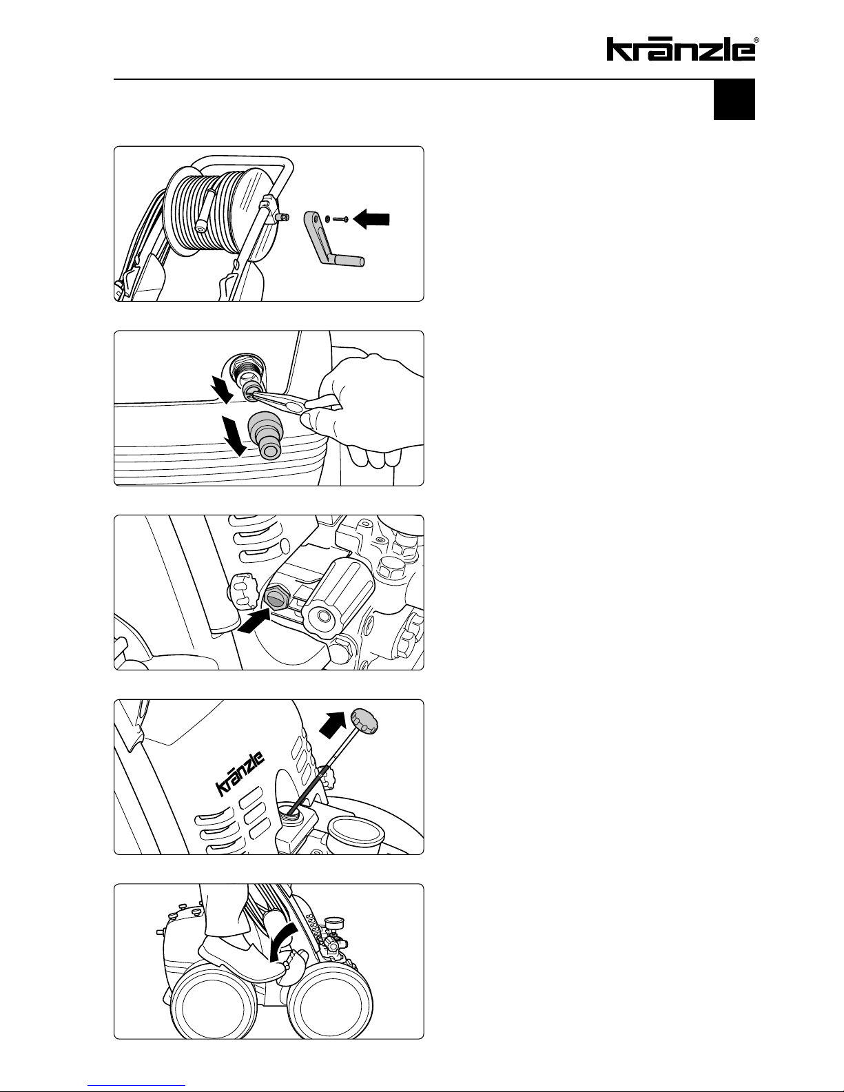
15
Putting into operation
1.
Release fixing screw from hexagonal
base of hose drum, put tiltable handle onto
the hexagonal base and fix with screw.
2
. Check water inlet filter for
cleanliness prior to putting the
machine into operation. Manually
unscrew hose attachment. Take out the
serial water inlet filter using needle nose
pliers and clean if filter is soiled.
4.
Release parking brake.
3.
Always check oil prior to putting the
cleaner into operation.
a) The oil-level glass must be filled
completely.
b) The oil level must be between the two
markings on the oil dipstick.
Page 16

5.
Move high-pressure cleaner to the job
site. The Kränzle quadros are movable
machines with sturdy trolleys ideally suited
for difficult terrain.
16
6.
Steering the machine: Put the foot
against the tilt bases and then pull the
device towards you.
For transport purposes the handle
together with the hose drum can be taken
off easily
.
First detach the high-pressure hose from
the drum.
Unscrew the 4 fixing screws and detach
handle and hose drum.
Page 17

17
9.
Release fixation of hose drum.
10.
Unwind HP hose from hose drum
without kinks and nooses.
Applicable for TS models without
hose drum: Screw high-pressure hose
to pump outlet.
8.
Screw together lance and gun
pressure-tightly.
7.
Push lance or Dirtkiller lance on to
gun.
Page 18

Putting into operation
18
12.
Screw high-pressure hose to gun
pressure-tightly.
11.
Push on high-pressure hose to gun.
14.
Connect to circuit.
400 V, 12 A, 50 Hz
The socket must be protected with a 16A
delay action fuse on the mains side.
13.
Connect water hose to water tank.
The cleaner may be connected to water
mains with cold or 60°C warm water.
Be careful when using hot water!
When running your high pressure cleaner with hot water
up to 60° C raised temperatures occur. Do not touch the
metal parts of the cleaner without safety gloves!
Page 19

19
15.
Steplessly adjust operating pressure
with handwheel. The maximum pressure
is adjusted ex works.
17.
Switch on high-pressure cleaner with
opened spray gun. Bleed appliance. Open
and close spray gun several times and
start cleaning task.
16.
Apply parking brake to prevent
machine from unintentional moving.
Setting up - Location
Neither set up and operate the machine in rooms where
there is a risk of fire or explosion nor put it into puddles.
Do not use the machine under water. The machine may
not be placed within reach of the water jet spray mist.
Page 20

Direct suction
Sucking in water from ponds, rain butts etc.
Due the suction capacity of its pump (up to 1.5 m suction height, max. hose length 3 m)
this high-pressure cleaner can suck in water for cleaning purposes from separate
containers or ponds. In this case the water tank has to be bypassed.
20
1.
Remove hose connecting
high-pressure pump and water tank from
the water tank.
(Bottom of the appliance shown).
2.
Screw hose connector 2 x 3/4“ (46.004)
and connecting hose together.
Best opt for suction hose with suction filter
from the Kränzle accessories: Order no.
15.038 3
Prior to starting the first suction process the pump resp.
the suction hose must be filled with water. Use clean
water only!
3.
Screw suction hose and hose
connector (46.004) together.
The inner diameter of the hose must be at
least 3/4“ = 16 mm.
Page 21

21
Suction of detergents
Detergent supply from the suction side:
Detergent injection on the pressure side, as you probably know it from other HP cleaners,
consume approx. 30 % of the cleaning energy, no matter if they are used or not. Due to the
water tank fitted to the Kränzle quadro models it is now possible to directly suck the detergent into the pump thus reducing output loss and increasing the efficiency considerably.
The detergents are applied without having to reduce the working pressure.
Only open the dosing valve, if the detergent sieve is
placed in a liquid. Sucked air leads to destruction of the
pump seals! No guarantee!
Keep detergent ph-value neutral 7 - 9!
Observe specifications of detergent manufacturer!
e.g.: protective equipment, rules for waste water
treatment etc.
Caution: dissolvents!
Never suck in liquids containing solvents like varnish
solvents, petrol, oil or similar liquid! Observe
specifications of detergent manufacturers!
Seals inside the appliance are no resistant against
solvents! The spray mist of solvents is highly
inflammable, explosive and poisonous
.
1.
Place detergent filter into detergent
container.
2.
Dosing of detergent is done by turning
the detergent valve.
3.
By closing the detergent valve the
supply of detergent is stopped.
Page 22

Decommissioning - Frost protection
01. Switch off the machine - main switch to „0“- position
02. Cut off the water supply
03. Open the spray gun briefly until the pressure is released
04. Apply the safety catch on the spray gun
05. Remove the water hose and spray gun
06. Drain the pump: switch on the motor for approx. 20 seconds
07. Pull the plug from the socket
08. Clean HP hose and wind up; fix drum
09. Clean power cable and wind up
10. Clean water filter
Frost protection
The machine is normally still partially filled with water after work has been completed. To
protect the appliance from frost, completely empty it of water: Disconnect the machine
from the water supply. Switch on the master switch and open the gun. The pump now
presses the remaining water out of the water tank and the pump. Do not allow the
machine to run for longer than a minute without water. For this purpose, fill the
antifreeze agent into the water tank and switch on the machine. Wait with opened gun,
until the agent comes from the nozzle.
However, the best protection against frost is to keep the machine in a place that is
safe from frost.
Due to their compact and space saving
design the Kränzle quadros can be stored
practically anywhere.
Store in a place-saving manner
22
Page 23

23
Small repairs
do it yourself
No water from the nozzle but the gauge shows full pressure:
Most likely the nozzle is blocked.
The pressure gauge shows full pressure,
but from the nozzle comes only little water
or no water at all.
(Inside the pressure gauge is no water but
a filling with glycerin to damp the vibration
of the pointer.)
Proceeding:
Switch off the cleaner. Pull plug from the
socket. Operate gun seveal times to
decrease the pressure.
First unscrew gun and lance, then rinse
hose from any residues.
Check water inlet filter for soiling.
Pull plug from socket prior to starting any repair
work!
If the problem still exists, take wire (paper clip) and push cautiously through nozzle
opening.
If this procedure is not successful, the nozzle has to be dismantled and cleaned (from the
backside) or even replaced, if necessary.
Page 24

Small repairs
do it yourself
Pressure gauge shows little pressure, the water from the nozzle
comes in squirts: Most likely the valves are soiled.
The pressure gauge shows little pressure
despite fully turned up pressure regulation.
The water from the lance comes in squirts.
The HP hose vibrates.
(Inside the pressure gauge is no water but
a filling with glycerine to damp the
vibration of the pointer.)
Proceeding:
Unscrew all 6 valves, one after the other
(hexagonal brass screws, 3 in a row,
vertically and horizontally)
Take out valve body (with green or red
plastic coating) and O-ring by means of
needle nose pliers. Check O-ring for
damage. In case of a damage the O-ring
has to be replaced.
Take a wire (paper clip) and clean valves
under running water. Also clean valve
seating inside the pump.
Do not forget the O-ring during
reassembly!
24
Page 25

25
Small repairs
do it yourself
The pressure gauge shows full pressure although the gun has
been closed. The pressure switch valve switches constantly.
Possible cause no.1: Leakage
Having closed the gun, the HP cleaner
must shut down and the pressure gauge
must show „0“ bar.
If the pressure gauge still shows full
pressure and the motor constantly
switches on and off, the possible reason
for this can be a leakage of the pump, the
HP hose or the lance.
Proceeding:
Check the connections from the HP
cleaner to the the HP hose, from the hose
to the gun and also the connection
between lance and gun for tightness.
Switch off the cleaner. Shortly press the
trigger of the gun to decrease the pressure.
Unscrew HP hose, gun and lance and
check the O-rings.
If the O-rings are damaged they have to
be replaced.
In case of a leakage there is no guarantee for possible
consequential damages.
Page 26

The pressure gauge shows full pressure although the gun has
been closed. The pressure switch valve switches constantly.
Possible cause no. 2:
The non-return valve is soiled
Proceeding:
Unscrew pump outlet.
Take out non-return valve ball and spring
and check for soiling or damage.
Replace non-return valve if necessary.
26
Small repairs
do it yourself
Page 27

There is no guarantee if the pump is damaged by defective
O-rings due to air induction or lack of water (cavitation).
27
Page 28

Kränzle quadro 1500 TS T,
Manfred Bauer, Fa. Josef Kränzle
Rudolf-Diesel-Str. 20, 89257 Illertissen
machinery directive 2006/42/EEC,
EMV-directive 2004/108/EEC,
noise directive 2005/88/EC, Art. 13,
HP water spraying machines
annex 3, part B, chapter 27
89 dB (A)
91 dB (A)
annex V, noise directive 2005/88/EC
EN 60 335-2-79 :2009
EN 55 014-1 :2006
EN 55 014-2 / A2:2008
EN 61 000-3-2 : 2006
EN 61 000-3-3 : 2008
28
EC declaration of conformity
Hereby we declare that:
technical specifications available from:
comply with the following guidelines
and their amendments for high-pressure
cleaners:
Sound level measured:
Sound level guaranteed:
Applied conformity evaluation procedures
Applied specifications and standards
I. Kränzle GmbH
Elpke 97
D - 33605 Bielefeld
Bielefeld, den 21.12.2009
(Managing director)
Page 29

Guarantee
The guarantee is only valid for material and manufacturing errors.
Wearing does not fall within this gurantee.
The instructions in our operating manual must be complied with..
The operating instructions form part of the guarantee. The Guarantee is void if other parts
are used than genuine Kränzle accessory parts or genuine Kränzle spare parts.
For high-pressure cleaners sold to the user the guarantee period is 24 month.
For high-pressure cleaners sold for industrial use the guarantee period is 12 month.
In the case of a guarantee please contact your dealer or authorized seller delivering
accessories and your purchase receipt. You can n them in the internet under
www.kraenzle.com.
The guarantee is also void if the machine is used with exceeding the temperature and
speed limits, a voltage below the required rating, with less than the required amount of
water or with dirty water.
Pressure gauge, nozzle, valves, sleeves, high pressure hose and spray equipment are
wear parts and are not covered by the warranty.
29
Page 30

Versatile due to Kränzle accessories
Rotating washing brush with 400 mm
extension, Order no. 41 050 1
Underbody lance with 800 mm extension,
Order no. 41 075
Tube cleaning hose with nozzle,
10 m - Order no. 41 058 1
20 m - Order no. 41 058 2
25 m - Order no. 41 058 3
30 m - Order no. 41 058 4
30
Page 31

Sludge sucker, stainless steel,
Order no. 41.801
Sludge sucker with 3 m suction hose,
Order no. 41.104
round cleaner ø 300 mm, Order no. 41.105
round cleaner light ø 300 mm, Order nor. 41.108
round cleaner ø 420 mm, Order no. 41.106
round cleaner ø 520 mm, Order no. 41.107
31
Suction hose with intake filter
Order no. 15.038 3
Page 32

Spare parts list
quadro 1500 TS / TST
Complete assembly
32
Page 33

1.1 Motor-Pumpe ohne Elektrik für quadro 1500 TST 1 42.622 4
1.2 Motor-Pumpe ohne Elektrik für quadro 1500 TS 1 42.622 9
2 Schubbügel 1 42.601
3 Sterngriffmutter M8 4 42.619
4 Stopfen 2 42.613
5 Wasserkasten 1 42.603
6 Lanzenablage 1 42.604
7 Kabelaufwicklung unten 1 42.611
8 Zugentlastung 1 43.431
9 Blechschraube 3,5 x 12 2 40.290
10 Kunststoffschraube 5,0 x 25 6 41.414
11 Scheibe 21 DIN125 12 40.207
12 Schraube M8x50 DIN912 2 42.620
13 Scheibe 8,4 DIN125 2 50.186
14 Kabelaufwicklung oben 1 42.612
15 Gummipuffer 25 x 25 4 44.227
16 Rad 4 44.017
17 Splint 5x28 DIN94 4 42.614
18 Radkappe 4 44.018
19.1 Frontplatte quadro 1500 TS 1 42.609 7
19.2 Frontplatte quadro 1500 TST 1 42.609 4
20 Lanzenhalter 2 42.610
21 Blechschraube 3,5x16 DIN7981 4 44.161
22 Fahrgestell 1 42.602
23 Scheibe 8,4 DIN9021 4 41.409
24 Elastic-Stop-Mutter M8 4 41.410
25 Netzanschlusskabel 8 m 1 44.036
26 Schlauchtrommel kpl. 1 41.259 6
39 Lanze mit Flachstrahldüse 2011 für 1500 TST 1 12.392-M2011
39.1 Lanze mit Flachstrahldüse 2010 für 1500 TS 1 12.392-M2010
bitte Düsengröße mit angeben
40 Starlett -Pistole mit Verlängerung 1 12.320 4
41 Turbo-Killer 11 bei quadro 1500 TST 1 41.580-11
41.1 Turbo-Killer 10 bei quadro 1500 TS 1 41.580-10
42 Hochdruckschlauch 20 m NW8 1 41.083
45 Scheibe 8mm für Rad 4 44.246
46 Gewindestift M6x55 4 42.617 2
Complete assembly quadro 1500 TS / TST
No Description Qty. Ord.-No.
33
Page 34

Spare parts list
quadro 1500 TS / TST
Brake
1 Grundplatte 1 42.615
2 Bremspedal 1 44.022
3 Bremshebel 1 44.023
4 Bremsklotz 1 44.024
5 Stift 6 x 50 1 44.035
6 Starlock-kappe 8 mm 1 44.165
7 Stift 6 x 40 1 44.035 1
8 Distanzring 2 42.626
9 Sechskantschraube M6x16 3 50.173
10 Unterlegscheibe DIN125-6,3 3 50.189
No Description Qty. Ord.-No.
34
Page 35

Spare parts list
quadro 1500 TS / TST
Water inlet
1 Mutter R3/4“ 1 46.258
2 Revisionsdeckel 1 42.605
3 Sterngriffmutter M8 4 42.619
6 Dichtung 1 46.261
8 Gewindestift M6x40 4 42.617 1
10 Wassereingangsteil 2x R3/4“ AG 1 42.804
11 Kupfer-Dichtring 1 42.820
12 T-Stück 3x R3/4“ IG 2 42.813
13 Schwimmerventil kurzes Gewinde 1 46.250 2
14 Schwimmerventil 1 46.250 1
20 Winkel-Stück R3/4“ IG / AG 2 42.636
21 Eingangsteil 2x R3/4“ AG 2 13.305
22 Verbindungsschlauch 2 42.637
No Description Qty. Ord.-No.
35
Page 36

Spare parts list
Kränzle quadro 1500 TS / TST
Pump motor
36
Page 37

Pump motor quadro 1500 TS / TST
1 Stator 112 5,5kW 400V / 50Hz 1 40.540
2 A-Lager Flansch 1 40.530
3 Rotor 112 (400V / 50Hz) 1 40.531 5
4 Lüfterrad für BG 112 1 40.532
5 Lüfterhaube BG 112 1 40.533
6 V-Seal 1 40.545
7 Flachdichtung 1 43.030
10 Kegelrollenlager 31306 1 40.103
11 Öldichtung 35 x 47 x 7 1 40.080
12 Passfeder 8 x 7 x 28 1 40.459
13 Kugellager 6206 - 2Z 1 40.538
14 Innensechskantschraube M 6 x 30 4 43.037
19 Schraube M 4 x 12 4 41.489
20 Schelle für Lüfterrad 112 2 40.535
21 Schraube M 4 x 12 4 41.489
22 Erdungsschraube kpl. 1 43.038
23 Schalter 14,5 A Amazonas 1 41.111 6
24 Kunststoffschraube 4,0 x 16 6 43.417
25 Bock für Schalter 1 42.608
26 Kunststoffschraube 5,0 x 25 6 41.414
28 Kunststoffschraube 3,5 x 20 2 43.415
29 Lüsterklemme 5-pol. 1 43.326 1
30 Schütz 100-C12KN10 3x400V 50/60 Hz 1 46.005 1
31 Schaltkasten Unterteil 1 42.606
32 Schaltkasten Deckel 1 42.607
33 Steuerplatine Abschaltverz. 400V / 50Hz 1 42.563
34 Klemmrahmen mit Schalterabdichtung 1 43.453
36 Blechschraube 3,5 x 16 2 44.161
37 PG 16-Verschraubung 1 41.419 1
38 Dichtung für Schaltkastendeckel 1 42.525
39 Gegenmutter für PG9-Verschraubung 1 41.087 1
40 Gegenmutter für PG16-Verschraubung 1 44.119
41 PG 9 - Verschraubung 1 43.034
42 Überstromauslöser 3-polig 11,3-16A 1 42.641
50 Motor kpl. ohne Schalter 24.060
51 Schaltkasten kpl. 42.631
No Description Qty. Ord.-No.
37
Page 38

Spare parts list
Kränzle quadro 1500 TS / TST
Pump transmission unit for AQ-pump
38
Page 39

Pump transmission unit for AQ-pump
quadro 1500 TS / TST
1 Ölgehäuse 1 40.501
4 Innensechskantschraube M 8 x 30 6 41.036 1
5 Sicherungsscheibe 6 40.054
6 Flachdichtung 1 40.511
7 Öldichtung 20 x 30 x 7 3 40.044 1
8 Wellenscheibe 1 40.043
9 Axial-Rollenkäg 1 40.040
10 Gehäusescheibe 1 40.039
11 Taumelscheibe AQ 15,5° 1 40.523-15,5
bei quadro 1500 TST + 1500 TS
12 Plungerfeder 3 40.506
13 Federdruckscheibe 3 40.510
14 Plunger 20 mm (lang) 3 40.505
15 Sprengring 3 40.048
16 O-Ring 14 x 2 1 43.445
18 Flachdichtung 1 41.019 3
19 Deckel ach für Ölgehäuse 1 41.023 1
20 Innensechskantschraube M 5 x 12 4 41.019 4
21 Ölmessstab AQ 1 42.623 1
22 Stützscheibe für Plungerfeder 3 40.513
23 O-Ring 13,94 x 2,62 1 42.167
24 Ölablassstopfen R 3/8“ 1 42.019
No Description Qty. Ord.-No.
39
Page 40

Spare parts list
Kränzle quadro 1500 TS / TST
Unloader valve and pressure switch
40
Page 41

Unloader valve and pressure switch
quadro 1500 TS / TST
5 O-Ring 16 x 2 1 13.150
5.1 O-Ring 13,94 x 2,62 1 42.167
8 O-Ring 11 x 1,44 1 12.256
9 Edelstahlsitz 1 14.118
10 Sicherungsring 1 13.147
11 Edelstahlkugel 1 13.148
12 Edelstahlfeder 1 14.119
13 Verschlussschraube 1 14.113
14 Steuerkolben 1 14.134
15 Parbaks 16 mm 1 13.159
16 Parbaks 8 mm 1 14.123
17 Spanstift 1 14.148
18 Kolbenführung spezial 1 42.105
19 Kontermutter M 8 x 1 2 14.144
20 Ventilfeder rot bei quadro 800 1 14.125 1
20.1 Ventilfeder schwarz bei quadro 1000, 1200 und 1500 1 14.125
21 Federdruckscheibe 1 14.126
22 Nadellager 1 14.146
23 Handrad 1 14.147
25 Elastic-Stop-Mutter M 8 x 1 1 14.152
26 Manometer 0-400 Bar 1 15.039 4
27 Aluminium-Dichtring 2 13.275
40 Sechskant - Mutter M 4 2 15.026
42 Druckfeder 1 x 8,6 x 30 1 40.520
50 O-Ring 3,3 x 2,4 1 12.136
51 Führungsteil Steuerstößel 1 15.009 1
52 O-Ring 13 x 2,6 1 15.017
53 O-Ring 14 x 2 1 43.445
54 Parbaks 4 mm 2 12.136 2
55 Stützscheibe 2 15.015 1
56 Edelstahlfeder 1 15.016
57 Steuerstößel 1 15.010 2
58 Parbaks 7 mm 1 15.013
59 Stopfen M 10 x 1 (durchgebohrt) 1 13.385 1
60 Gehäuse Elektroschalter 1 15.007
61 Gummimanschette PG 9 1 15.020
62 Scheibe PG 9 1 15.021
63 Verschraubung PG 9 1 15.022
64 PVC-Kabel 2x 1,0 mm² 1 42.505
65 Blechschraube 2,8 x 16 6 15.024
66 Deckel Elektroschalter 1 15.008
67 O-Ring 44 x 2,5 1 15.023
68 Mikroschalter 1 44.262
69 Zylinderschraube M 4 x 20 2 15.025
70 Steuerkolben kpl. mit Handrad 43.444
71 Rep.- Satz Druckschaltermechanik 15.009 3
72 Druckschalter kpl. 41.300 5
73.1 Ventilgehäuse kpl. quadro 800 – 1200 TS 42.638 1
73.2 Ventilgehäuse kpl. quadro 800 – 1200 TST 40.503 6
73.3 Ventilgehäuse kpl. quadro 1500 TS 42.638 3
73.4 Ventilgehäuse kpl. quadro 1500 TST 42.638 2
No Description Qty. Ord.-No.
41
Page 42

Spare parts list
Kränzle quadro 1500 TS / TST
Valve housing for integrated AQ-pump
42
No Description Qty. Ord.-No.
Repair kit for sleeves 40.065 1
consisting of: 3x Items 13; 6x Items 14; 3x Items 15;
3x Items 16;3x Items 18; 3x Items 20; 3x Items 23
Repair kit for sleeves without 40.517
brass parts consisting of:
3x Items 13; 6x Items 14; 3x Items 15; 3x Items 18; 3x Items 23
Repair kit valves 40.062 1
consisting of: 6x Items 2; 6x Items 3; 6x Items 4
Page 43

1 Ventilgehäuse AQ mit integr. UL und Druckschalter 1 40.503 5
2 O-Ring 18 x 2 6 40.016
3 Einlaß- / Auslaß- Ventil 6 42.024
4 O-Ring 21 x 2 6 42.025
5 Ventilstopfen 5 42.026
5.1 Ventilstopfen mit R 1/4“ IG 1 42.026 2
6 Sicherungsring 4 40.032
7 Innensechskantschraube M 12 x 45 4 40.504
9 Schlauchschelle 7 - 10 1 44.054
10 Chemiesaugschlauch mit Filter 1 42.621
11 Winkel 12L x 12L 1 42.630
12 Verschlussschraube R 1/2“ mit R1/4“ IG 1 44.121
13 Gewebemanschette 3 40.023
14 Backring 20 mm 6 40.025
15 O-Ring 31,42 x 2,62 3 40.508
16 Leckagering 20 x 36 x 13,3 3 40.509
17 Cu-Dichtring 21 x 28 x 1,5 2 42.039
18 Gummimanschette 3 40.512
19 Verschlussschraube R 1/2“ 1 42.032
20 Distanzring mit Abstützung 3 40.507
21 Aluminium-Dichtring bei quadro TS 2 13.275
22 Verschlussstopfen bei quadro TS 1 13.181
23 Druckring 20 mm 3 40.021
24 Zwischenring 20 mm 3 40.516
25 O-Ring 11 x 1,5 1 12.256
26 Edelstahlsitz Ø 7 1 14.118
27 Sprengring 1 13.147
28 Ausgangsteil Pumpe R1/4“ x 12 1 44.215
29 Dichtring 17 x 22 x 1,5 (Kupfer) 1 40.019
30 Stopfen 3/8“ 1 40.018
31 Dichtstopfen M 10 x 1 1 43.043
32 Dichtstopfen M 8 x 1 2 13.158
33 Ausgangsteil für quadro 1500 TST 1 40.522
33.1 Ausgangsteil M22x1,5 für quadro 1500 TS 1 40.522 1
34 Edelstahlkugel Ø10 1 12.122
35 Rückschlagfeder „K“ 1 14.120 1
37 O-Ring 18 x 2 1 43.446
38 Messingrohr bds. R3/8“ 2 41.628
39 Winkel 2x 3/8“ IG 2 44.138
40 Wassereingang R3/8“ AG 2 41.016
44 Winkel R1/4“ IG/AG 1 40.121
45 Grundteil Eckventil 1 46.600
46 Ventilnadel 1 46.601
47 Scheibe 1 43.045
48 Parbaks 6 mm 1 46.606
49 O-Ring 1 12.256
50 Führungsteil 1 46.602
51 Handrad 1 46.603
52 Scheibe 1 43.045
53 Schraube M4x8 Messing 1 46.604
54 Saugzapfen M6 1 46.605
55 Chemieventil R 1/4“ kpl. 1 46.610
Valve housing quadro 1500 TS / TST
No Description Qty. Ord.-No.
43
Page 44

Spare parts list
Kränzle quadro 1500 TS / TST
Hose drum
44
Page 45

Hose drum
quadro 1500 TS / TST
1 Seitenschale Schlauchführung 1 40.302
2 Seitenschale Wasserführung 1 40.301
3 Trommel Unterteil 1 40.304
4 Trommel Oberteil 1 40.303
5 Innensechskantschraube M 4 x 25 4 40.313
6 Lagerklotz mit Bremse 1 40.306
7 Lagerklotz links 1 40.305
8 Klemmstück 2 40.307
9 Kunststoffschraube 5,0 x 20 12 43.018
10 Antriebswelle 1 40.310
11 Welle Wasserführung 1 40.311
12 Elastic-Stop-Mutter M 4 4 40.111
13 Handkurbel klappbar 1 40.320 0
14 Verriegelungsbolzen 1 40.312
15 Scheibe MS 16 x 24 x 2 1 40.181
16 Wellensicherungsring 22 mm 2 40.117
17 Wellensicherungsring 16 mm 1 40.182
20 Parbaks 16 mm 2 13.159
21 Sicherungsscheibe 6 DIN6799 1 40.315
22 Schraube M 5 x 10 1 43.021
23 Drehgelenk 1 40.167
25 Distanzring 1 40.316
27 O-Ring 6,86 x 1,78 1 40.585
28 Anschlussstück 1 40.308
33 O-Ring 6 x 1,5 1 13.386
34 Stopfen M 10 x 1 1 13.385
40 Überwurfmutter 1 13.276 2
42 O-Ring 9,3 x 2,4 4 13.273
44 Verbindungsschlauch 1 42.624
45 Hochdruckschlauch NW 8 20 m 1 41.083
Hose drum compl. without HP-hose 41.259
No Description Qty. Ord.-No.
45
Page 46

1 Ventilkörper mit Handgriff 1 12.294
2 Schutzhülse 1 12.295
3 Abdeckschutz 1 12.296
4 Betätigungshebel grau 1 12.298 3
5 Sicherungshebel 1 12.149
6 Abschlussschraube M 16 x1 1 12.247
7 Stopfen 1 12.287
8 Gewindeführungshülse Ø3 R 1/4“ AG 1 12.250 1
9 Aufsteuerbolzen Ø3 1 12.284 1
10 Stift 1 12.148
11 Lagernadel 1 12.253
12 Edelstahlfeder 1 12.246
13 Edelstahlkugel 1 12.245
14 Edelstahlsitz 1 13.146
15 O-Ring 11 x 1,44 1 12.256
16 O-Ring 2,84 x 2,62 1 12.136 1
17 Blechschraube 3,9 x 8 4 12.297
18 Druckstück 1 12.252
19 Rohr kunststoffumspritzt bds. R 1/4” AG 1 15.004 5
20 Überwurfmutter ST 30 M22 x 1,5 IG 1 13.276 1
21 Außen-Sechskant-Nippel R 1/4” IG 1 13.277 1
22 O-Ring 9,3 x 2,4 1 13.273
23 Aluminium-Dichtring 4 13.275
24 O-Ring 15 x 1,5 1 12.129 1
25 Sicherungsring 1 12.258
26 Gleitschuh Ø3 1 12.289 1
51 Düsenschutz 1 26.002
52 Rohr 500 mm; bds. R1/4” 1 12.385 1
53 ST 30 Nippel M 22 x 1,5 / R1/4” m. ISK 1 13.370
54 Flachstrahldüse 2504 (bei quadro 800) 1 D2504
54.1 Flachstrahldüse 2505 (bei quadro 1000) 1 D2505
54.2 Flachstrahldüse 2507 (bei quadro 1200) 1 D2507
54.3 Flachstrahldüse 2511 (bei quadro 1500 TST) 1 M2511
54.4 Flachstrahldüse 2510 (bei quadro 1500 TS) 1 M2510
Starlet-Pistole mit Verlängerung 12.320 4
Spare parts list
Kränzle quadro 1500 TS / TST
Gun 'Starlet'
46
No Description Qty. Ord.-No.
Page 47

Kränzle quadro 1500 TS / TST
Turbokiller
47
11 Sprühkörperschutz 1 41.528
12 Sprühkörper 1 41.529
13 O-Ring 6,88 x 1,68 1 41.521
14 Düsensitz 1 41.522
15 Düse 045 für quadro 800 1 41.532 1
15.1 Düse 055 für quadro 1000 1 41.532
15.2 Düse 08 für qudro 1200 1 41.537
15.3 Düse 11 für qudro 1500 TST 1 41.537 2
15.4 Düse 10 für qudro 1500 TS 1 41.537 1
16 Ring 1 41.533
17 Rotor 1 41.534
18 Stabilisator 1 41.524
19 O-Ring 41 x 1,78 1 41.538
20 Deckel 1 41.539
21 Deckelschutz 045 1 41.540
22 Rohr 600 mm lang; bds. R1/4” 1 12.385 2
23 Nippel M22x1,5 x R1/4” IG 1 13.370
Turbokiller 045 kpl. mit Lanze 41.072 3
Turbokiller 055 kpl. mit Lanze 41.072 4
Turbokiller 08 kpl. mit Lanze 41.072 8
Turbokiller 10 kpl. mit Lanze 41.072 1
Turbokiller 11 kpl. mit Lanze 41.580-11
Rep.-Satz Turbokiller 045 41.097 6
Rep.-Satz Turbokiller 055 41.097 1
Rep.-Satz Turbokiller 08 41.097 3
Rep.-Satz Turbokiller 10 41.097 5
Rep.-Satz Turbokiller 11 41.096 8
No Description Qty. Ord.-No.
Page 48

Wiring diagramme
Kränzle quadro 800 TS T -
1200 TS 400 V, 50 Hz
On-Off switch with 14,5 Ampere
overload protection
Pressure switch
Pump motor
3 x 400 V / 50 Hz
Inlet line via
CEE 5 x 16 A
400 V / 50 Hz
48
Excess
current
release
12 A
Control board with
Transformer 400 V / 50 Hz
Page 49

The appliance was checked by an expert according to the Guidelines for Liquid
Spray Equipment, the defects found have been rectified so that the Labour Safety can be
confirmed.
The appliance was checked by an expert according to the Guidelines for Liquid
Spray Equipment. The Labour Safety cannot be confirmed unless the defects found are
rectified by repair or replacement of the faulty parts.
The next retest according to the Guidelines for Liquid Spray Equipment has to be carried
out by: Month Year
Place, date Signature
49
Type plate (on hand)
Operating manual (on hand)
Protective covering, -device
Pressure line (tightness)
Pressure gauge (function)
Float valve (tightness)
Spraying device (marking)
HP-hose / connector (damage, marking)
Safety valve opens at 10 % / 20 % exceeding of operang pr.
Power cable (damage)
Protective conductor (connectedt)
On / Off switch
Used chemicals
Allowed chemicals
High-pressure nozzle
Operating pressure..................bar
Switch off pressure..................bar
Conductor resistance not exceeded / value
Insulation
Leakage current
Gun locked
Inspection report for HP cleaners
Professionally used high pressure cleaners must be inspected by an expert every 12 months!
Inspection report on annually carried out Labour Safety Inspection (UVV) according to the
Guidelines for Liquid Spray Equipment. (This inspection sheet serves as proof for the completion of
the retest and must be kept carefully!)
Kränzle-Test Stamp Mark: Order Number UVV200106
Scope of inspection ok yes no repaired
Inspection data determined value set value
Inspection result (tick)
Owner:
Address:
Type:
Serial no:
Rep.-order-no:
Page 50

50
The appliance was checked by an expert according to the Guidelines for Liquid
Spray Equipment, the defects found have been rectified so that the Labour Safety can be
confirmed.
The appliance was checked by an expert according to the Guidelines for Liquid
Spray Equipment. The Labour Safety cannot be confirmed unless the defects found are
rectified by repair or replacement of the faulty parts.
The next retest according to the Guidelines for Liquid Spray Equipment has to be carried
out by: Month Year
Place, date Signature
Type plate (on hand)
Operating manual (on hand)
Protective covering, -device
Pressure line (tightness)
Pressure gauge (function)
Float valve (tightness)
Spraying device (marking)
HP-hose / connector (damage, marking)
Safety valve opens at 10 % / 20 % exceeding of operang pr.
Power cable (damage)
Protective conductor (connectedt)
On / Off switch
Used chemicals
Allowed chemicals
High-pressure nozzle
Operating pressure..................bar
Switch off pressure..................bar
Conductor resistance not exceeded / value
Insulation
Leakage current
Gun locked
Inspection report for HP cleaners
Professionally used high pressure cleaners must be inspected by an expert every 12 months!
Inspection report on annually carried out Labour Safety Inspection (UVV) according to the
Guidelines for Liquid Spray Equipment. (This inspection sheet serves as proof for the completion of
the retest and must be kept carefully!)
Kränzle-Test Stamp Mark: Order Number UVV200106
Scope of inspection ok yes no repaired
Inspection data determined value set value
Inspection result (tick)
Owner:
Address:
Type:
Serial no:
Rep.-order-no:
Page 51

51
The appliance was checked by an expert according to the Guidelines for Liquid
Spray Equipment, the defects found have been rectified so that the Labour Safety can be
confirmed.
The appliance was checked by an expert according to the Guidelines for Liquid
Spray Equipment. The Labour Safety cannot be confirmed unless the defects found are
rectified by repair or replacement of the faulty parts.
The next retest according to the Guidelines for Liquid Spray Equipment has to be carried
out by: Month Year
Place, date Signature
Type plate (on hand)
Operating manual (on hand)
Protective covering, -device
Pressure line (tightness)
Pressure gauge (function)
Float valve (tightness)
Spraying device (marking)
HP-hose / connector (damage, marking)
Safety valve opens at 10 % / 20 % exceeding of operang pr.
Power cable (damage)
Protective conductor (connectedt)
On / Off switch
Used chemicals
Allowed chemicals
High-pressure nozzle
Operating pressure..................bar
Switch off pressure..................bar
Conductor resistance not exceeded / value
Insulation
Leakage current
Gun locked
Inspection report for HP cleaners
Professionally used high pressure cleaners must be inspected by an expert every 12 months!
Inspection report on annually carried out Labour Safety Inspection (UVV) according to the
Guidelines for Liquid Spray Equipment. (This inspection sheet serves as proof for the completion of
the retest and must be kept carefully!)
Kränzle-Test Stamp Mark: Order Number UVV200106
Scope of inspection ok yes no repaired
Inspection data determined value set value
Inspection result (tick)
Owner:
Address:
Type:
Serial no:
Rep.-order-no:
Page 52

S ub j e c t to t e c h n i c a l mo d if i c a ti o n s . Or d e r no . 3 0 . 6 0 4 1
I . K r ä n z l e G m b H
E l p k e 9 7
D - 3 3 6 0 5 B i e l e f e l d
R e p r i n t o n l y a l l o w e d w i t h t h e a u t h o r i z a t i o n o f K r ä n z l e .
A s d a t e o f 0 3 . 0 1 . 2 0 11
 Loading...