

Page 1

www.kraenzle.com
Operating manual
H i g h - p r e s s u r e c l e a n e r
- GB -
Read and conform safety instructions before use!
Keep instructions in a safe place for later use and
pass them on to any future user.
Page 2

10 - 170 bar
190 bar
8.7 l/min
2503
03
7 l
max. 60 °C
60 °C
2.5 m
yes
15 m
230 V/50 Hz, 14 A
1400 rpm
P1: 3.1 kW
P2: 2.3 kW
45 kg
590 x 360 x 850
84 dB (A)
89 dB (A)
88 dB (A)
2,0 m/s²
approx. 20 N
2
Operating pressure,
steplessly adjustable
max. permissible
overpressure
Water output
at nominal pressure
Nozzle size
(Flat jet)
(Dirt killer)
Volume
Water tank
Inlet water
temp. to water tank
Max. temp. for
direct suction
Direct suction height
Hose drum
High pressure hose
Electrical ratings
Motor speed adjust.
Connect.wattage Inp.
Output
Weight (incl. access.
with empty water tank)
Dimensions incl. handle L
x W x H in mm
Sound level acc. to
DIN 45 635 (reg.
working place)
with dirtkiller
Guaranteed sound
level L
WA
Vibrations at lance
Recoil at lance
10 - 140 bar
155 bar
11.0 l/min
25045
045
7 l
max. 60 °C
60 °C
2.5 m
yes
15 m
230 V/50 Hz, 14 A
1400 rpm
P1: 3.1 kW
P2: 2.3 kW
45 kg
590 x 360 x 850
84 dB (A)
89 dB (A)
88 dB (A)
2,0 m/s²
approx. 20 N
quadro
11/140 TST
Technical
data
Technical data
quadro
9/170 TST
Permissible tolerance for gures ± 5 % in acc. with VDMA uniform sheet 24411
*1
Min. water quantity to be supplied to the high pressure cleaner!
(2-8 bar admission pressure)
*2
Direct suction is possible through by-passing of water tank!
(see page 13)
*1
*2
10 - 150 bar
165 bar
12.0 l/min
25045
045
7 l
max. 60 °C
60 °C
2.5 m
yes
15 m
400 V/50 Hz, 7 A
1400 rpm
P1: 3.1 kW
P2: 2.5 kW
45 kg
590 x 360 x 850
88 dB (A)
90 dB (A)
88 dB (A)
2,1 m/s²
approx. 20 N
quadro
12/150 TST
Page 3

Dear customer
We would like to congratulate you on your new high pressure cleaner with integrated water tank and to thank you for the purchase.
To ease your introduction to the use of the cleaner, we have provided the following
pages of explanations, tips and hints, which we ask you to read before using it for
the rst time.
The equipment will assist you professionally in all cleaning tasks, e.g.:
- facades
- agstones
- terraces
- vehicles of all types
- stables
- machines etc.
- barrels and containers
- channels
Description
Contents Page
Technical data .................................................... ....2
Connection principle and components ....................4
Water system ..........................................................5
Detergent / caring system .......................................5
Lance and spay gun ................................................5
High pressure hose and spray device .....................6
Unloader valve - safety valve ..................................6
Total stop system ....................................................7
Setting up / Location ...............................................7
Electrical connection ...............................................8
Brake .......................................................................9
Brief operating instructions......................................9
This is what you’ve purchased ...............................10
Preparation for use.................................................11
External suction......................................................13
When using detergents ..........................................14
To shut down the pump / Frost protection ..............14
Safety notes „This is prohibited !“...........................15
Additional accessories ...........................................18
Small repairs ..........................................................20
Spare parts lists .....................................................22
Wiring diagram .......................................................44
General rules / oil change / guarantee ...................46
Declaration of conformity .......................................47
Inspection report ....................................................48
3
Page 4
1
2
3
4
8
9
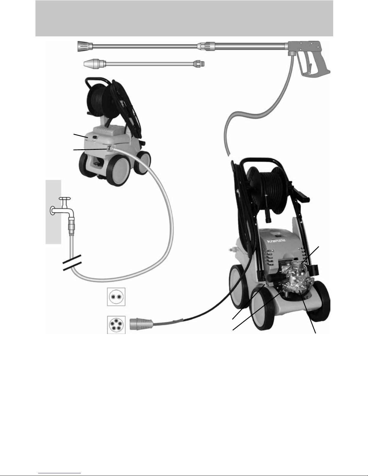
6 Detergent valve
7 High pressure hose
8 Spray gun
9 Interchangeable lance with at jet
nozzle and nozzle protection
10 Interchangeable lance with dirtkiller
1 Water inlet connection with lter
2 Cover for water tank
3 High pressure pump
4 Press. gauge with glycerin lling
5 Unloader valve - safety valve
quadro 12/150
400V/50Hz
Connection principle
The KRÄNZLE quadro 9/170; 11/140 and 12/150 - high pressure cleaners are mobile
machines with hose drum and 20 m industrial hose.
The connection principle can be seen from the illustration.
Components
Description
10
7
6
4
quadro 9/170
quadro 11/140
230V/50Hz
5
Page 5

Water supply system
The water must be lead to the high pressure cleaner under pressure (2 – 8 bar
ad-mission pressure). A oat valve regulates the water inlet. Then, the water is
sucked by the high pressure pump from the water tank and supplied to the lance
under the set pressure. The high pressure jet is formed by the nozzle at the end of
the lance.
Detergent and caring system
The high pressure pump can also suck a detergent/caring
agent and mix it with the high pressure jet. The additive
is sucked through the pump and brought in with the set
pressure.
Insert the detergent hose into the detergent container and
open the detergent valve (6). The detergent must have
the ph-value 7-9 neutral.
The detergent discharges with the water at the high pressure nozzle.
Only open the dosing valve, if the chemistry sieve is placed in
a liquid. Sucked air leads to destruction of the pump seals !!!
The rules concerning the environment, refuse and
ground water protection must be complied with!
Description
5
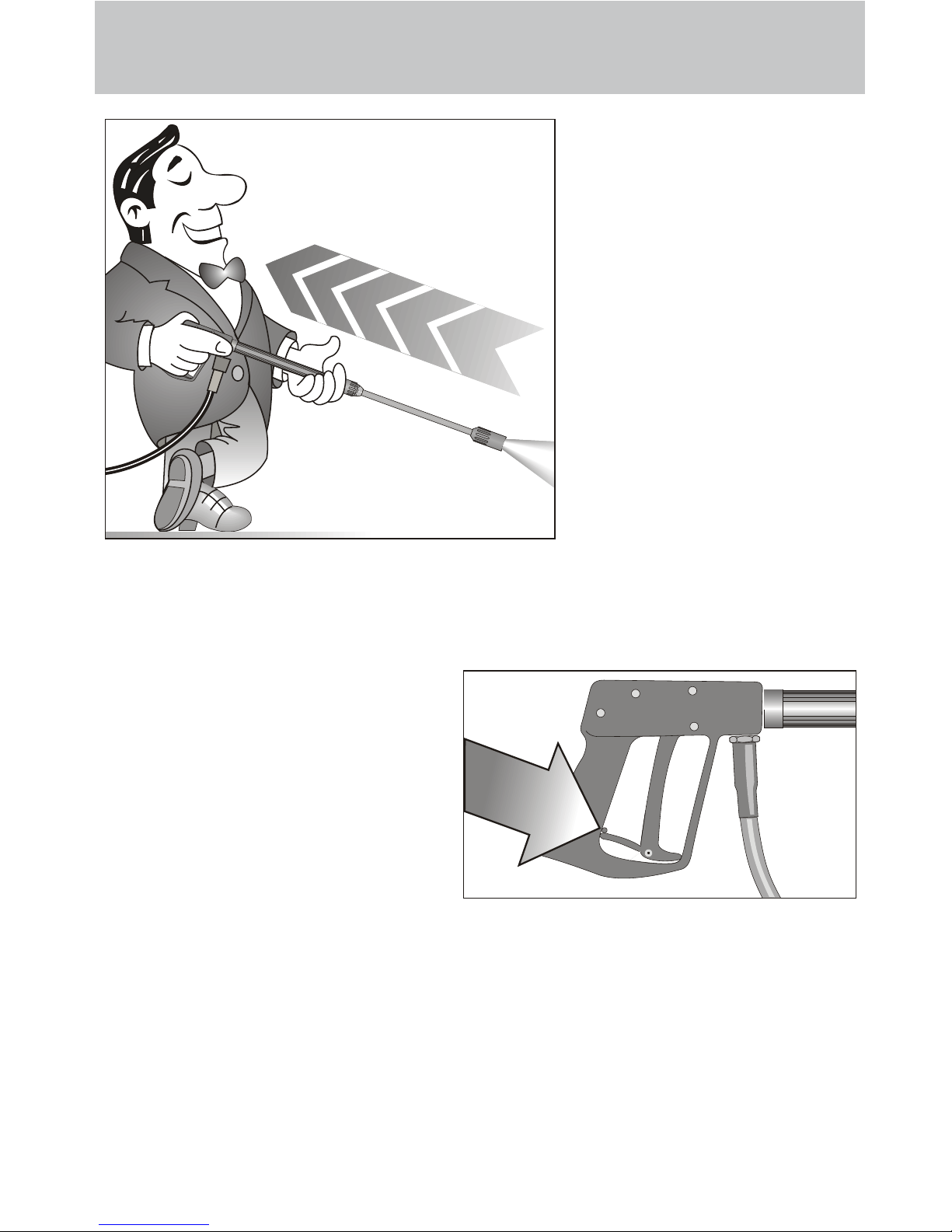
Lance with spray gun
The machine can only be operated when the safety trigger is squeezed.
When the lever is squeezed, the spray gun opens. The liquid is then pumped
to the nozzle. The spray pressure increases and quickly reaches the selected
operating pressure. For the deairing of the system open and close the gun quickly
a few times. When the trigger is released, the trigger gun closes and any further
spraying of liquid from the lance is stopped and the pressure gauge must show 0
bar.
The increase in pressure when the trigger gun is closed causes the unloader
valve-safety valve to open. The pump remains switched on and continues to pump
liquid through the pump at reduced pressure. When the spray gun is opened, the
unloader valve - safety valve closes and the pump ressumes spraying from the
lance with the selected operating pressure.
The spray gun is a safety device. Repairs should only
be performed by qualied persons. Should replacement
parts be required, use only components authorized by
the manufacturer.
6
Page 6

Description
6
High pressure hose and spraying device
The high pressure hose and spraying device supplied with the machine are made
of high grade material. They are also optimized for the machine and marked as
required by the appropriate regulations.
If replacement parts are required, only such parts that are authorized
by the manufacturer and which bear the markings required by the
appropriate regulations may be used. The high pressure hose and
spraying device must be connected in a pressure-tight manner.
The high pressure hose may not be driven over, pulled excessively or
twisted. Hose lines are wear parts. Guarantee is accepted only for ma-
nufacturing errors, not for external damages.
High pressure hose lines and spraying equipment must not be repaired, but replaced by a new hose or spraying equipment.
Unloader valve - safety valve
The unloader valve - safety valve protects the machine from a build up of excess
pressure, and is designed not to permit an excess pressure to be selected for
operation. The limit nut on the handle is sealed with a spray coating.
The operating pressure and spray rate can be steplessly adjusted by
turning the handle.
Replacements, repairs, new adjustments and sealing
should only be performed by qualied persons.
Take care that all screw connections are pressure-tight.
A leakage of gun, high-pressure hose or hose drum has to
be repaired at once. Leakages lead to an increased wear
and to a possible malfunction of the delayed motor cut-out.
Operator’s task:
Prior to each usage of this liquid spraying device, the operator is obliged to check if all safety relevant parts are in
perfect working condition. (e.g. safty valves, high-pressure
hose, cables and connections, spraying devices, etc. )
Page 7

With Total-Stop-System
The Kränzle quadro 9/170 TS, 11/140 TS und 12/150 TS - high
pressure cleaners are equipped with a Total-Stop-System.
If the main switch is switched on, the motor is started by means
of a pressure switch as soon as the gun is operated. The pump quickly reaches
the set operating pressure. When the gun is closed the motor is cut off immediately.
Replacements and inspection work should only be performed by qualied persons when the machine is disconnected from the
power supply, i.e. the plug pulled out from the electrical
socket.
Setting up
Location
Neither set up and operate the machine in rooms where there is a risk
of re or explosion nor put it into puddles. Do not use the machine under
water. The device must not stand in the spray area of the high pressure jet.
CAUTION !
Never suck in liquid containing solvents such as paint thinners, petrol,
oil or similar liquid matter. Pay attention to the instructions of
the manufacturers of the cleaning agents. The seals in the
machine are not resistant to solvents! The spray of solvents is inammable, explosive and poisonous.
CAUTION !
When running your high pressure cleaner with hot water of 60° C
raised temperatures occur. Do not touch the machine without
safety gloves!
7
Description
Page 8
Description
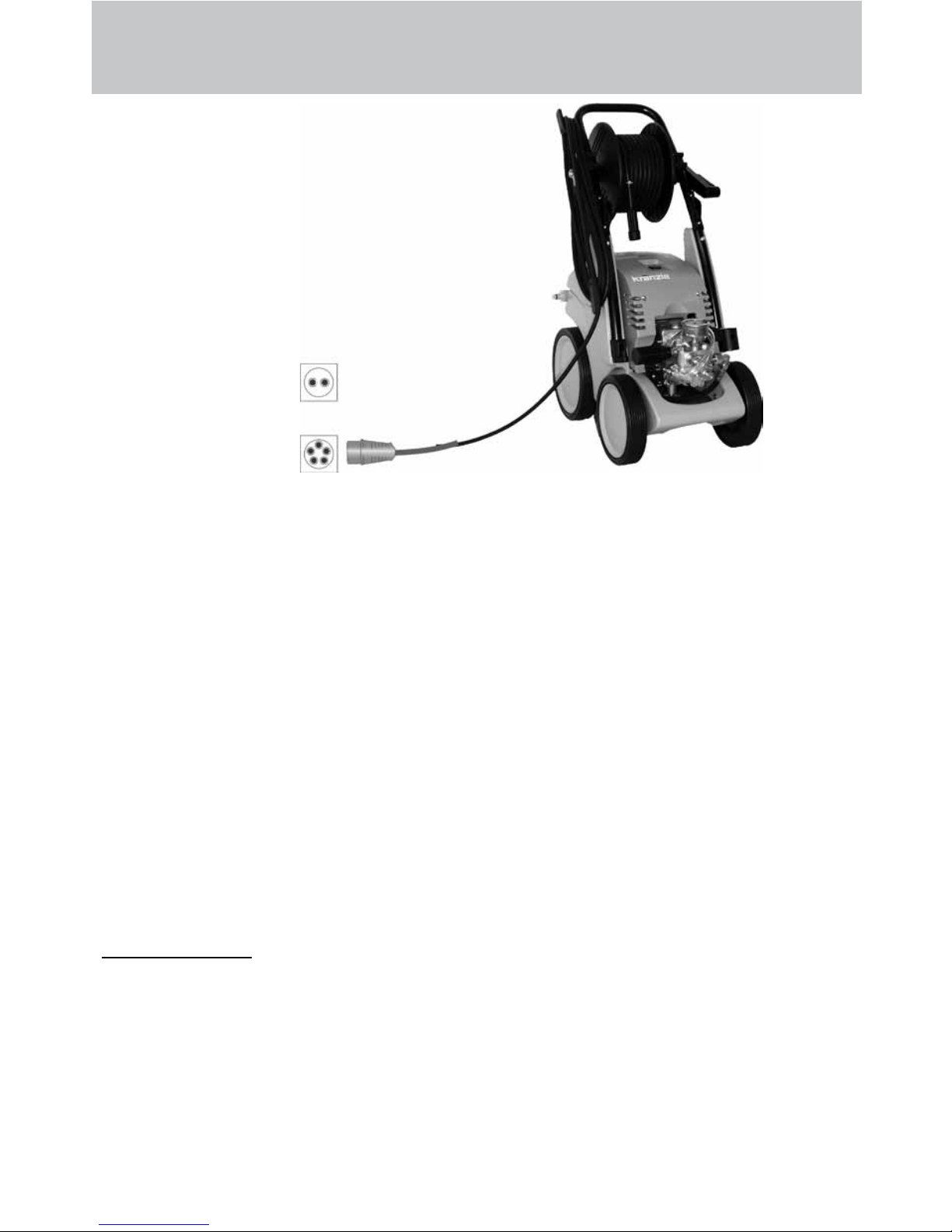
Electrical connection
The machine is supplied with an electrical power cord with plug.
The mains plug must be tted to a standard grounded socket with a 30mA residual current operated device. The socket must be protected with a 16A delay
action fuse on the mains side.
KRÄNZLE quadro 9/170 TST, 11/140 TST = 230 Volt / 50 Hz
KRÄNZLE quadro 12/150 TST = 400 Volt / 50 Hz
(phase-sequence not signicant)
When using an extension cable, this must have a grounded lead which is properly
connected to the socket. The conductors in the extension cable must have a minimum cross section of 1.5 mm². Plug connections must be of a spray-proof design
and may not be located on a wet oor.
CAUTION !
The use of extension cables which are too long may lead to malfunctions and start
up difculty. If the extension cable is longer than 10 m it must have a minimum cross
section of 2.5mm².
When using a cable drum, always keep the cable unwound as far as possible.
8
quadro 12/150
400V/50Hz
quadro 9/170
quadro 11/140
230V/50Hz
Page 9
9
Description
Brief operating instructions:
1. Connect high pressure hose with spray gun.
2. Connect to suitable water supply.
3. Connect current (see page 8).
4. Switch on machine, operate gun and start cleaning.
5. After having completed the cleaning process, put main switch in zero position and by opening the gun, reduce the pressure in the high pressure
hose.
Then, the high pressure hose can be rolled up.
- Only use clean water ! Protect from frost !
CAUTION !
Please pay attention to the regulations of your waterworks company.
Due to the water tank, the device can be connected to any drinking water line
without any difculties.
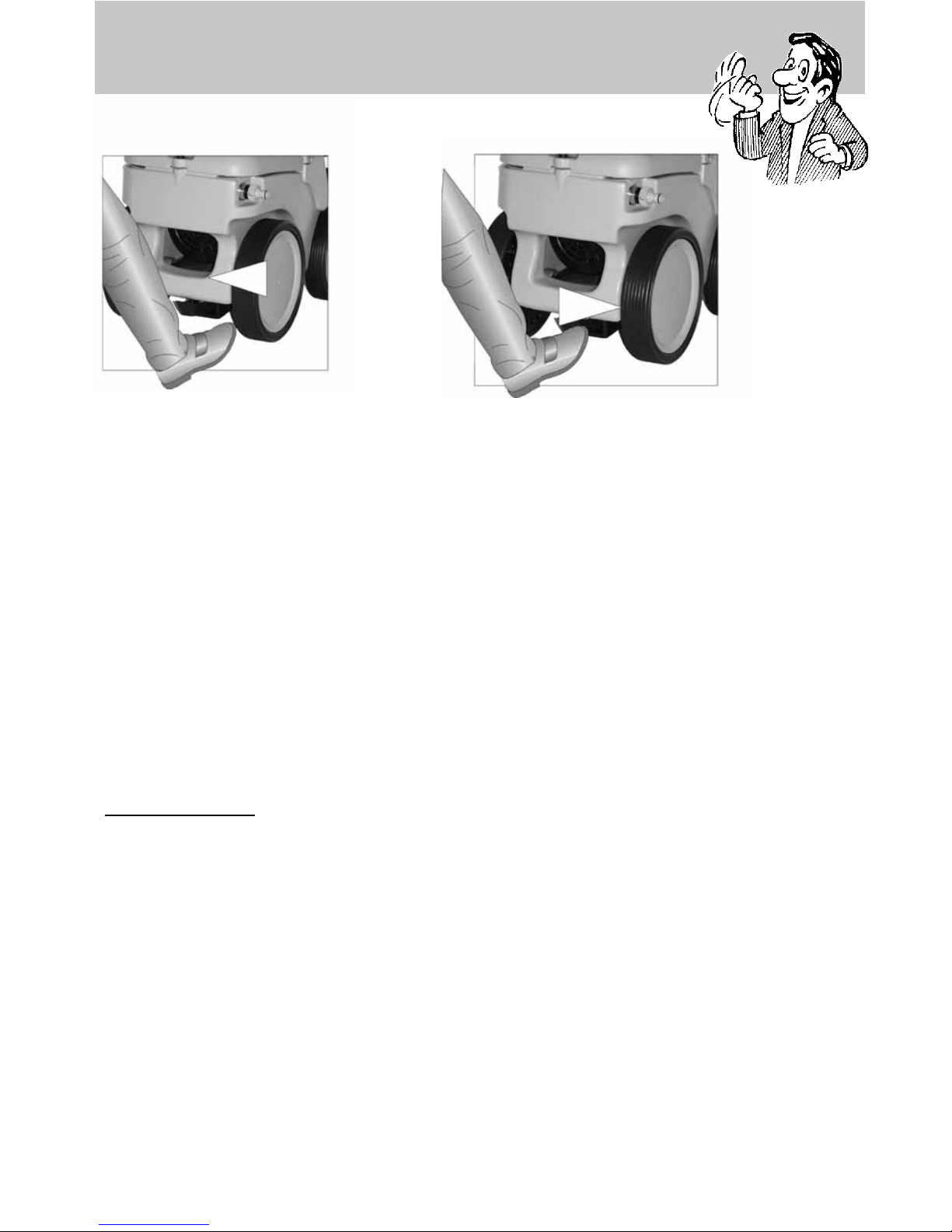
Brake applied
Brake not applied
Brake
Page 10
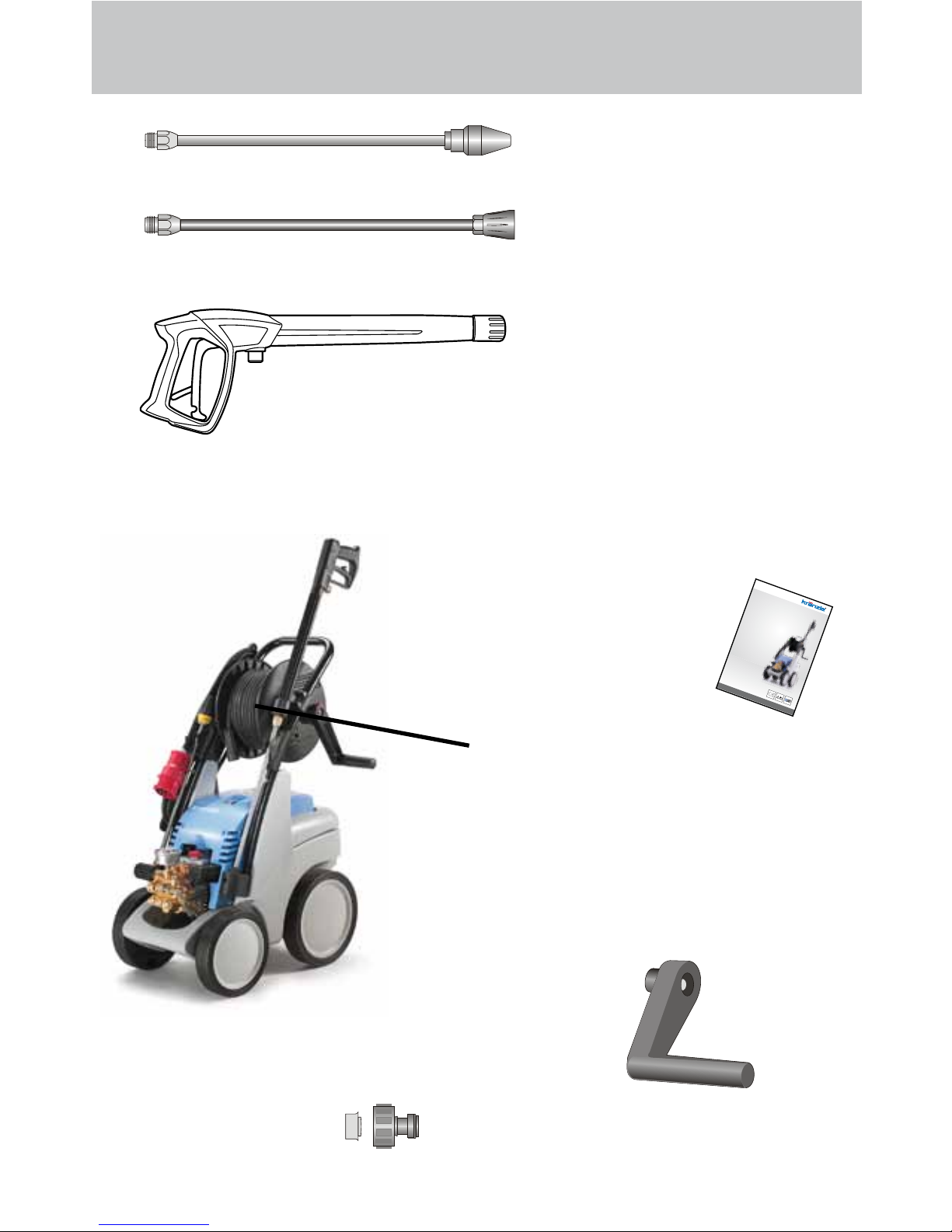
This is what you’ve purchased:
1. Dirtkiller
Lance with nozzle
protection and high
pressure nozzle
Flat jet 25°
2. Spray gun M2000
with insulated handle
and screw connection
3. KRÄNZLE - High pressure cleaners
quadro 9/170, 11/140 and 12/150 TST with hose drum and
15 m HP hose NW 6 with steel reinforcement
4. Operating manual
5. HP hose 15 m NW 6 with hose drum
7. Plug-in connection of
water inlet parts and
lter (already installed)
6. Collapsible crank
for hose drum
(already installed)
10
www.kraenzle.com
Page 11
Preparation for use
11
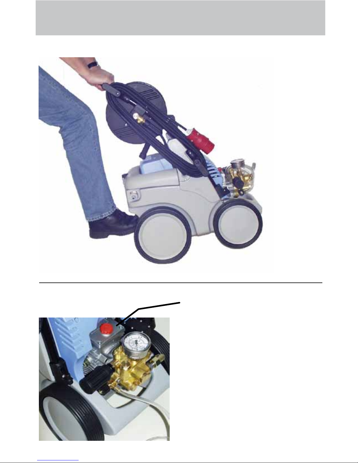
To control the high pressure cleaner
put
1. the foot against the tilt bases and
2. then pull the device towards you.
1. Check oil level.
The oil level must be between the
two markings on the oil dipstick.
Page 12
Preparation for use
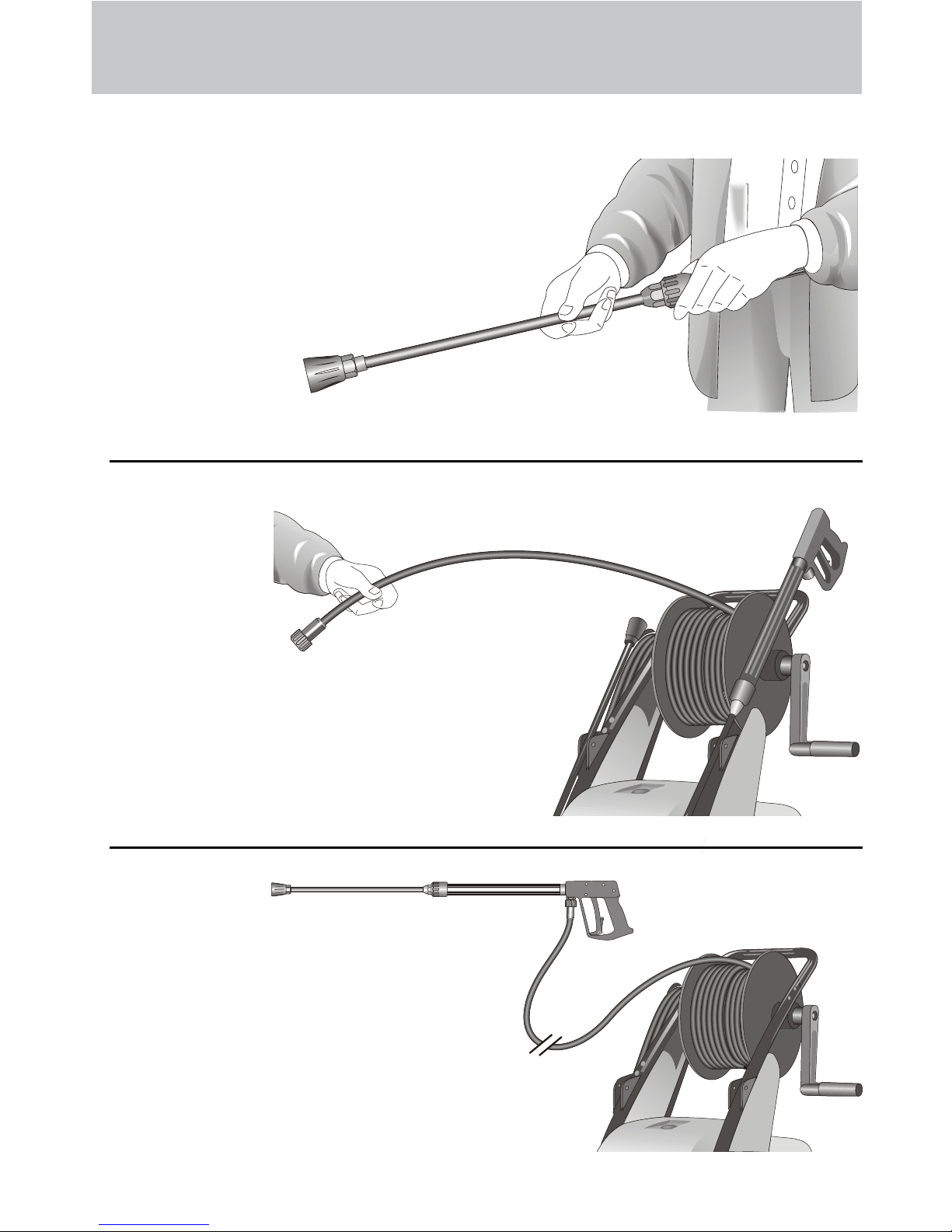
3. Unroll hose without kinks and connect with handgun and pump. Use
max. 20 m HP hose.
4. Connection of high pressure
hose from device to lance.
2. Connect the high pressure lance
or dirtkiller to the spray gun.
12
Page 13
Preparation for use
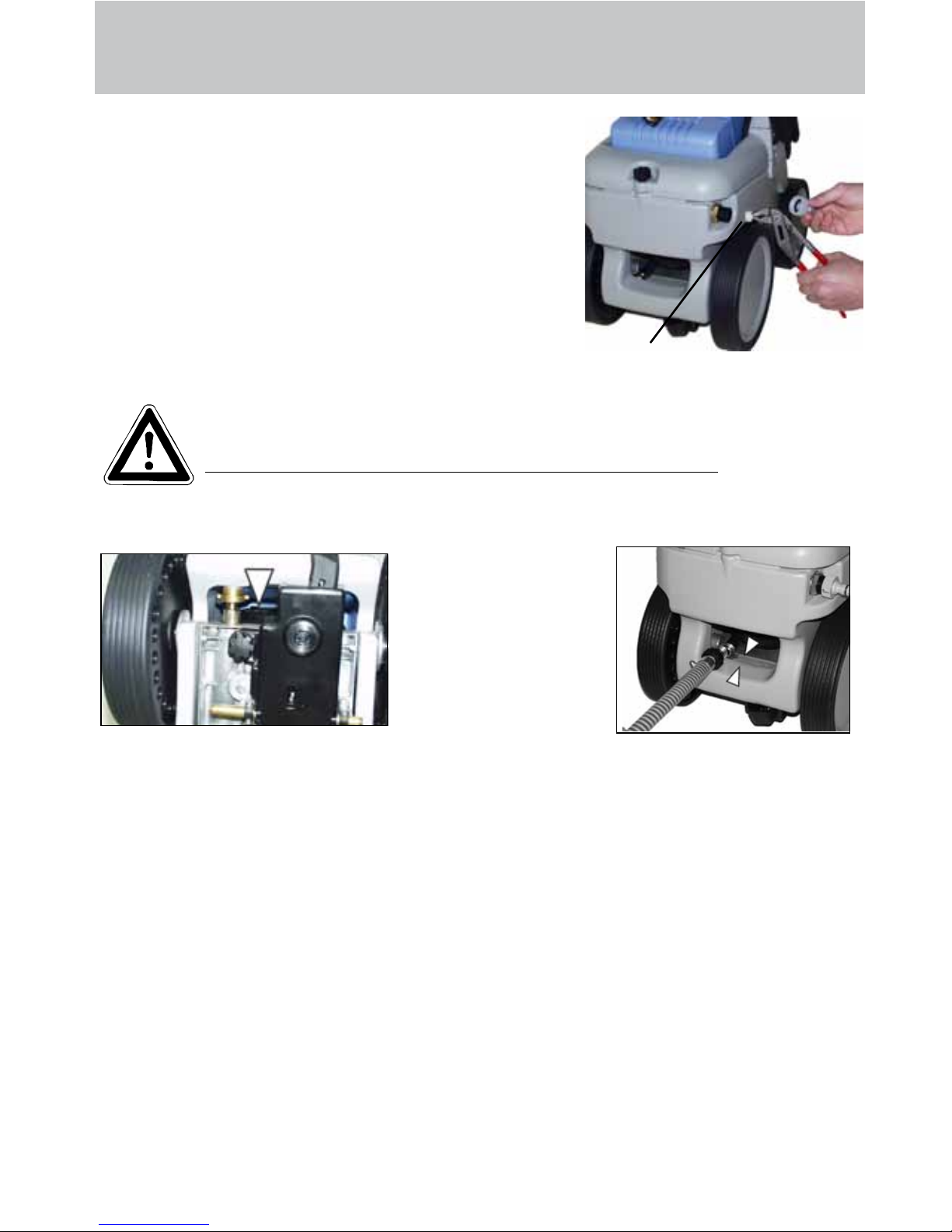
5. The machine must be connected to the water
line with cold water or up to 60° C warm water
(see page 2).
The hose cross section must be at least
3/4" = 16 mm (free passage). Filter 1 must
always be clean.
Please make sure that the lter is clean be-
fore using your high pressure cleaner.
CAUTION !
When running your high pressure cleaner with hot water of 60° C raised temperatures occur.
Do not touch the pump without safety gloves!
13
Undercarriage
Undercarriage
1
External suction
If water is to be sucked
from an external container for the high pressure
cleaner, the connection
hose between the high
pressure pump and the
water tank must be screwed off and the suction
hose must be connected
via a double nipple 3/4“ (Order no.: 46.004) to the connection hose.
Make sure that the water is clean. Use the Kränzle suction hose with suction lter.
(Order no. 15.038 3)
Maximum suction height 2.5 m, maximum water temperature for direct suction: 60°C
(see technical data on page 2)
Page 14
14
To shut down the pump
1. Switch off the machine. Switch to „0“ position.
2. Cut off the water supply.
3. Open the spray gun briey until the pressure is released.
4. Apply the safety catch on the spray gun.
5. Remove the water hose and spray gun.
6. Pull the plug from the socket.
7. Winter: store the pump in rooms above 0°C.
8. Clean the water lter.
To shut down the pump:
Frost protection
Normally after operation, there is still some water in the device. Thus, you must take
special measures to protect the device from frost.
- Completely drain the device
For this purpose, separate the device from the water supply. Then, turn on the
main switch and open the gun. Now, the pump presses the remaining water out of
the water tank and the pump. However, do not allow the device to operate without
water for longer than one minute.
- Fill the device with antifreeze agent
If the device is not operated for longer periods, especially over the winter, you
should pump an antifreeze agent through the device. For this purpose, ll the anti-
freeze agent into the water box and turn on the device. Wait with opened gun,
until the agent spurts out of the nozzle.
However, the best way to protect the device from frost is
to store it at a frost-free location.
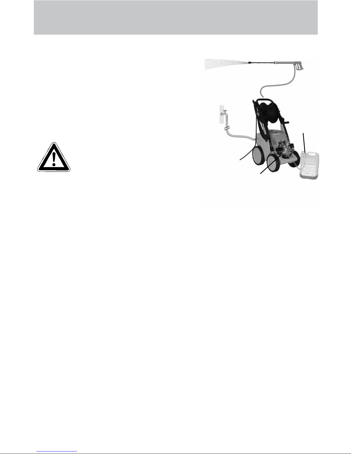
Suction of detergents
Put chemistry sieve number 5 into the detergent container. Open the detergent valve (6),
then the detergent is sucked in. When closing
the detergent valve, the chemistry supply is
automatically closed. Allow detergent to act and
then wash off. (see page 5).
Note that you must always comply with the
instructions provided by the manufacturer of the detergent (e.g. safety
clothing) and the water protection regulations!
Only open the valve, if the chemistry sieve
is in a liquid. Sucked in air leads to the
destruction of the pump seals !!!
Damages to the pump caused by sucked in air
are not covered by the guarantee.
5
6
Page 15
Safety notes
As to the recoil see notice on page 2!
Apply the safety catch on the
spray gun after each use, in
order to prevent unintention-
al spraying!
15
Page 16
16
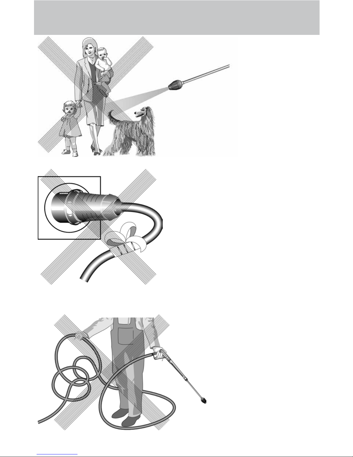
This is prohibited !
Do not damage the
power cable or repair it incorrectly!
Never direct the
water jet at people
or animals !
Never pull the high
pressure hose if it
has formed kinks or
“nooses”!
Never pull the hose
over sharp edges !
Page 17

17
This is prohibited !
Never allow children to use the high
pressure cleaner !
Never direct the
water jet at the machine itself !
Never direct the
water jet at a power socket !
Page 18

Additional accessories for ...
(on demand)
Rotary scrubbing brush
Order No. 41.050 1
Drain and pipe cleaning
hose
10 m - Order No. 41.058.1
15 m - Order No. 41.058
Environmental, refuse disposal and water protection
regulations must be observed when using the accessories!
18
Page 19

... further combination possibilities
Car cleaning, glass, caravan, boat etc.: rotary washing brush with 40 cm extension and
ST 30 nipple M22 x 1.5
Cleaning pipes, channels and drains: pipe
cleaning hose with KN nozzle and ST 30
nipple M22 x 1.5
Rotary point sprayer for extreme soiling:
Turbokiller with 40 cm extension and ST 30
nipple M22 x 1.5
Cleaning cars and all smooth surfaces:
brush with ST 30 nipple M22 x 1.5
19
Page 20

Small repairs
The nozzle is blocked!
No water but the gauge shows full pressure !
remove the lance and clean
the nozzle.
Using the at spray lance you
only have to clean the front
nozzle.
Straighten a paper
clip and clean the
nozzle.
Insert pointed object
into the hole and pull
the cap back!
Check visually whether the
nozzle is clean.
Now it works as well
as before.
20
Rinse the hose
through rst.
You should now have a
powerful stream of
water,
but if you
only get a few
drops of water
from the
lance
Page 21

...do it yourself !
Nozzle dirty or sticky!
Pressure gauge does not show full pressure
Water comes out in spurts.
If you do not use the high-pressure cleaner for some time the valves can stick.
The high-pressure hose vibrates.
Straighten a
paper clip...
When a valve is
blocked,
the gauge
shows little
pressure or
no pressure
at all
or the high
pressure
hose
vibrates!
Open the valve
with a socket
wrench...
and remove the
valve screw, the
valve and the
o-ring.
Replace the rubber o-ring.
and remove the
dirt from the valve
- the valve inside
must be closed.
Retighten the
valve screw
...and repeat
on all 6 valves.
Now it works
as well as
before!
21
Page 22

22
Complete Assembly
Page 23

23
quadro 9/170 - 12/150 TST
Spare parts list KRÄNZLE quadro 9/170 - 11/140 - 12/150 TST
Complete assembly
No Description Qty. Ord.-No
No Description Qty. Ord.-No
Motor-Pumpe ohne Elektrik
1.1 für quadro 9/170 TST 1 46.582 1
1.2 für quadro 11/140 TST 1 46.582 2
1.3 für quadro 12/150 TST 1 46.582 3
Motor-Pumpe mit Elektrik
1.4 für quadro 9/170 TST 1 46.583 1
1.5 für quadro 11/140 TST 1 46.583 2
1.6 für quadro 12/150 TST 1 46.583 3
2 Schubbügel 1 46.504
3 Schraube M6x35 DIN6912 6 46.024
4 Scheibe 6,4 DIN125 4 50.189
5 Wasserkasten 1 46.510
6 Rammschutz vorn 1 46.511
7 Kabelaufwicklung 1 46.507
8 Zugentlastung 1 43.431
9 Kunststoffschraube 4,0 x 16 2 43.417
10 Kunststoffschraube 5,0 x 30 2 41.412
11 Lanzenständer 1 46.502
12 Köchertopf 1 46.503
13 Rad d210 2 44.538
14 Radkappe d210 2 46.011
15 Gummipuffer 20 x 25 4 46.547
16 Rad d250 2 46.508
17 Federstecker 4 40.115 1
18 Radkappe d250 2 46.509
19.1 Frontplatte quadro 9/170 TST 1 46.535 1
19.2 Frontplatte quadro 11/140 TST 1 46.535 2
19.3 Frontplatte quadro 12/150 TST 1 46.535 3
20 Lanzenhalter 2 42.610
21 Blechschraube 3,5x16 DIN7981 8 44.161
22 Fahrgestell 1 46.501
23 Schraube M6x12 2 43.421
24 Schraube M6x12 4 44.090 1
25 Netzanschlusskabel 5,75m 1 41.092
Wechselstrom (quadro 9/170 - 11/140)
25.1 Netzanschlusskabel 8m 1 44.036
Drehstrom (quadro 12/150)
26 Schlauchtrommel kpl. 1 46.581
27 Chemiesaugschlauch (Gewebe) mit Filter 1 42.621
28 Kabelführung mit Zugentlastung 1 46.506
29 Verbindungsschlauch Schlauchtrommel 1 46.537
39.1 Lanze mit Flachstrahldüse für 9/170 TST 1 12.393-M2003
39.2 Lanze mit Flachstrahldüse
für 11/140 TST und 12/150 TST 1 12.393-M20045
40 Pistole M2000 1 12.480
41.1 Schmutz-Killer 03 bei quadro 9/170 TST 1 41.570-03
41.2 Schmutz-Killer 045
bei quadro 11/140 TST und 12/150 TST 1 41.570-045
42 Hochdruckschlauch 15 m NW6 1 40.170
43 O-Ring 13 x 2,6 2 13.272
44 Verbindungsschlauch Wasserkasten 1 46.536
45 Scheibe 40 x 19 x 1,5 4 46.533
47 Rückschlagventil für Chemiesaugschl. 1 44.240
Page 24

24
Water inlet and brake
Page 25

25
No Description Qty. Ord.-No
Spare parts list KRÄNZLE quadro 9/170 - 11/140 - 12/150 TST
Water inlet and brake
quadro 9/170 - 12/150 TST
1 Revisionsdeckel 1 46.512
2 Dichtung Revisionsdeckel 1 46.513
3 Sterngriffschraube M6 1 46.031
4 Schwimmerventil 1 46.250 1
5 Mutter R3/4“ 1 46.258
6 Kunststoffschraube 5x14 1 43.426
7 Scheibe 5,3 DIN9021 1 50.152
8 Zugfeder 1 46.020
9 Deckel Bremse 1 46.016
10 Hebel Bremse 1 46.505
11 Sternschraube M8 1 50.168
12 Innensechskantschraube M4x10 4 46.002
13 Schelle 2 43.431
14 Bolzen für Bremse 1 46.018
15 Dichtung für Schwimmerventil 1 46.261
16 Bundschraube 1 46.019
Page 26

26
Pump motor
Page 27

27
quadro 9/170 - 11/140 TST
No Description Qty. Ord.-No
Spare parts list KRÄNZLE quadro 9/170 - 11/140 TST
Pump motor
Schaltkasten kpl. Pos. 22 - 54 46.585
Motor kpl. ohne Schalter Pos. 1 - 22 46.586
1 Ölgehäuse für AP mit Deckel und Dichtung 1 46.530 1
2 Motorgehäuse mit Stator Wechselstrom 1 46.528
3 Rotor mit Motorwelle 1 43.316
4 Passfeder 6 x 6 x 20 1 41.483 1
5 Motor-Lager B-Seite 6205 - 2Z 1 43.317
6 Motor-Lager Schulterlager 7304 1 41.027
8 Öldichtung 25 x 35 x 7 1 41.024
9 Lüfterrad BG 90 1 43.319
10 Lüfterhaube BG 90 1 43.320
18 Schraube M 4 x 22 4 41.489 1
19 Kabel mit Stecker 1 41.092
23 Innensechskantschraube M 6 x 30 4 43.037
24 Erdungsschraube kmpl. 1 43.038
25 Schraube M 4 x 12 6 41.489
26 Schelle für Lüfterrad 1 43.454
27 Kunststoffschraube 5,0 x 25 6 41.414 1
28 Kunststoffschraube 3,5 x 20 2 43.415
29 Lüsterklemme 5-pol. 1 43.326 1
31 Schaltkasten Unterteil 1 46.012
32 Schaltkasten Deckel 1 46.013
33 Schalter 14,5 A Amazonas 1 41.111 6
34 Klemmrahmen mit Schalterabdichtung 1 43.453
36 Blechschraube 3,5 x 14 2 44.525
37 PG 16-Verschraubung 1 41.419 1
38 Dichtung für Schaltkastendeckel 1 42.525
39 Gegenmutter für PG9-Verschraubung 2 41.087 1
40 Gegenmutter für PG16-Verschraubung 1 44.119
41 PG 9 - Verschraubung 1 42.541
42 Kondensator 70µF 1 43.322
43 PG 9 – Verschraubung reduziert 1 41.087
50 Gummidichtung für Schalterdistanzstück 1 41.111 3
51 Unterteil für Schalterdistanzstück 1 41.111 1
52 Runddichtung für Schalterdistanzstück 1 41.111 5
53 Oberteil für Schalterdistanzstück 1 41.111 2
54 Flachdichtung für Schalterdistanzstück 1 41.111 4
Page 28

28
Pump motor
Page 29

quadro 12/150 TST
29
Spare parts list KRÄNZLE quadro 12/150 TST
Pump motor
No Description Qty. Ord.-No
Switch box compl. items 22 - 54 46.584
Motor compl. without switch items 1 - 22 46.587
1 Ölgehäuse für AP 1 46.530 1
2 Motorgehäuse mit Stator Drehstrom 1 46.529
3 Rotor mit Motorwelle 1 43.316
4 Passfeder 6 x 6 x 20 1 41.483 1
5 Motor-Lager B-Seite 6205 - 2Z 1 43.317
6 Motor-Lager Schulterlager 7304 1 41.027
8 Öldichtung 25 x 35 x 7 1 41.024
9 Lüfterrad BG 90 1 43.319
10 Lüfterhaube BG 90 1 43.320
19 Kabel mit Stecker Drehstrom 1 44.036
22 Kunststoffschraube 4,0 x 16 2 43.417
23 Innensechskantschraube M 6 x 30 4 43.037
24 Erdungsschraube kpl. 1 43.038
25 Schraube M 4 x 12 6 41.489
26 Schelle für Lüfterrad 1 43.454
27 Kunststoffschraube 5,0 x 25 6 41.414 1
28 Kunststoffschraube 3,5 x 20 2 43.415
29 Lüsterklemme 5-pol. 1 43.326 1
30 Schütz 100-C12KN10 3x400V 50/60 Hz 1 46.005 1
31 Schaltkasten Unterteil 1 46.012
32 Schaltkasten Deckel 1 46.013
33 Schalter 8 A Amazonas 1 41.751
34 Klemmrahmen mit Schalterabdichtung 1 43.453
36 Blechschraube 3,5 x 14 2 44.525
37 PG 16-Verschraubung 1 41.419 1
38 Dichtung für Schaltkastendeckel 1 42.525
39 Gegenmutter für PG9-Verschraubung 2 41.087 1
40 Gegenmutter für PG16-Verschraubung 1 44.119
41 PG 9 - Verschraubung 1 42.541
50 Gummidichtung für Schalterdistanzstück 1 41.111 3
51 Unterteil für Schalterdistanzstück 1 41.111 1
52 Runddichtung für Schalterdistanzstück 1 41.111 5
53 Oberteil für Schalterdistanzstück 1 41.111 2
54 Flachdichtung für Schalterdistanzstück 1 41.111 4
Page 30

30
Pump
Page 31

31
quadro 9/170 TST
No Description Qty. Ord.-No
Spare parts list KRÄNZLE 9/170 TS T
Pump with plunger, diameter 15 mm
AP pump complete with 15mm plungers
for quadro 9/170 46.588-14,5
consisting of: items 1-18
1 Gehäuseplatte für 15 mm Plunger 1 42.906
2 Öldichtung 15 x 24 x 7 3 42.907
3 O-Ring Viton 88 x 2 1 41.021 1
4 Plungerfeder 3 41.033
5 Federdruckscheibe 15 mm 3 42.909
6 Plunger 15 mm 3 42.908
7 Sprengring 15 mm 3 42.910
8 Taumelscheibe 14,3° 1 41.028-14,3
10 Axial-Rillenkugellager 3-teilig 1 43.486
12 Innensechskantschraube M 8 x 30 4 41.036 1
14 O-Ring 14 x 2 2 43.445
15 Dichtung für Deckel 1 46.531
16 Deckel für Ölgehäuse 1 46.532
17 Schraube M5x12 4 41.019 4
18 Ölmessstab AP 1 46.546
20 Ölablassstopfen M18x1,5 mit Magnet 1 48.020
Page 32

32
Pump
Page 33

33
quadro 11/140 - 12/150 TST
No Description Qty. Ord.-No
Ersatzteilliste KRÄNZLE 11/140 - 12/150 TS T
Pump with plunger, diameter 18 mm
AP pump complete with 18mm plungers
for quadro 11/140 46.589-12,5
consisting of: items 1-18
AP pump complete with 18mm plungers
for quadro 12/150 46.589-13,5
consisting of: items 1-18
1 Gehäuseplatte für 18 mm Plunger 1 41.020 2
2 Öldichtung 18 x 28 x 7 3 41.031
3 O-Ring Viton 88 x 2 1 41.021 1
4 Plungerfeder 3 41.033
5 Federdruckscheibe 18 mm 3 41.034
6 Plunger 18 mm 3 41.032 1
7 Sprengring 18 mm 3 41.035
8 Taumelscheibe 12,5° (quadro 11/140 TST) 1 41.028-12,5
8.1 Taumelscheibe 13,75° (quadro 12/150 TST) 1 41.028-13,75
10 Axial-Rillenkugellager 3-teilig 1 43.486
12 Innensechskantschraube M 8 x 30 4 41.036 1
14 O-Ring 14 x 2 2 43.445
15 Dichtung für Deckel 1 46.531
16 Deckel für Ölgehäuse 1 46.532
17 Schraube M5x12 4 41.019 4
18 Ölmessstab AP 1 46.546
20 Ölablassstopfen M18x1,5 mit Magnet 1 48.020
Page 34

34
Unloader valve and pressure switch
Page 35

35
quadro 9/170 - 12/150 TST
Spare parts list KRÄNZLE quadro 9/170 - 12/150 TST
Unloader valve and pressure switch
No Description Qty. Ord.-No
No Description Qty. Ord.-No
Rep.-kit Pressure switch mech. 15.009 3
consisting of: 1x items 51; 1x items 52;
1x items 53; 3x items 54; 1x items 55; 1x items 56;
1x items 57; 1x items 58; 1x items 59
Guide piston compl. w. hand wheel 40.490
items 5, 14-25
5 O-Ring 16 x 2 1 13.150
5.1 O-Ring 13,94 x 2,62 1 42.167
8 O-Ring 1 12.256
9 Edelstahlsitz 1 14.118
10 Sicherungsring 1 13.147
11 Edelstahlkugel 8,5 mm 1 13.148
12 Edelstahlfeder 1 14.119
13 Verschlussschraube 1 14.113
14 Steuerkolben 1 14.134
15 Parbaks 16 mm 1 13.159
16 Parbaks 8 mm 1 14.123
17 Spannstift 1 14.148
18 Kolbenführung spezial 1 42.105
19 Mutter M 8 x 1 2 14.144
20 Ventilfeder schwarz 1 14.125
21 Federdruckscheibe 1 14.126
22 Nadellager 1 14.146
23 Handrad 1 40.457
24 Kappe Handrad 1 40.458
25 Elastic-Stop-Mutter 1 14.152
26 Manometer 0-250 bar 1 15.039
27 Aluminium - Dichtring 2 13.275
50 O-Ring 3,3 x 2,4 1 12.136
51 Führungsteil Steuerstößel 1 15.009 1
52 O-Ring 13 x 2,6 1 15.017
53 O-Ring 14 x 2 1 43.445
54 Parbaks 4 mm 2 12.136 2
55 Stützscheibe 2 15.015 1
56 Edelstahlfeder 1 15.016
57 Steuerstößel lang 1 15.010 2
58 Parbaks 7 mm 1 15.013
59 Stopfen M10x1 (durchgebohrt) 1 13.385 1
60 Gehäuse Elektroschalter 1 15.007
61 Gummimanschette PG 9 1 15.020
62 Scheibe PG 9 1 15.021
63 Verschraubung PG 9 1 15.022
64 Kabel 2 x 1,5 mm² für 9/170 - 11/140 TS 1 46.515
64.1 Kabel 2 x 1,0 mm² für quadro 12/150 TS 1 46.516
65 Blechschraube 2,8 x 16 6 15.024
66 Deckel Elektroschalter 1 15.008
67 O-Ring 44 x 2,5 1 15.023
68 Mikroschalter 1 15.018
69 Zylinderschraube M 4 x 20 2 15.025
70 Sechskant-Mutter M 4 2 15.026
72 Druckfeder 1 x 8,6 x 30 1 40.520
Page 36

36
Valve housing
Page 37

37
No Description Qty. Ord.-No
No Description Qty. Ord.-No
Spare parts list KRÄNZLE 9/170 TS T
Valve housing APG for plunger diameter 15 mm
KRÄNZLE 9/170 TS T
Rep.-kit valves for APG-pump 41.748 1
consisting of: 6x items 4; 6x tems 5; 6x tems 6
Repair kit for sleeves 15 mm 42.911
consisting of 3x items 27; 3x items 28;
3x items 28.1; 6x tems 29; 3x items 30
Valve housing compl. 15 mm 46.590
with integr. ULH and pressure switch Chemical valve compl. 46.610
consisting of: 1x items 20-26
1 Ventilgehäuse 1 42.163 3
2 Ventilstopfen 5 41.714
2.1 Ventilstopfen mit R1/4“ IG 1 42.026 1
3 Dichtstopfen M 10 x 1 1 43.043
4 Ventile (grün) für APG-Pumpe 6 41.715 1
5 O-Ring 16 x 2 6 13.150
6 O-Ring 15 x 2 6 41.716
7 Dichtstopfen R1/4” mit Bund 1 42.103
8 Ausgangsteil 1 40.522
9 Dichtstopfen M 8 x 1 2 13.158
10 O-Ring 18 x 2 1 43.446
11 Aluminium - Dichtring 3 13.275
12 Ausgangsteil Pumpe R1/4” x 12 1 46.039
13 Ermeto-Winkel 12 L x 12 L 1 42.630
14 Ermetowinkel R3/8“ x 12L 1 44.092
15 Sprengring 1 13.147
15 Edelstahlkugel Ø10 1 12.122
17 Rückschlagfeder „K“ 1 14.120 1
18 O-Ring 11 x 1,5 2 12.256
19 Edelstahlsitz Ø 7 1 14.118
19.1 Scheibe 6 mm 2 43.045
20 Grundteil Eckventil 1 46.600
21 Ventilnadel 1 46.601
22 Parbaks 6 mm 1 46.606
23 Führungsteil 1 46.602
24 Handrad 1 46.603
25 Schraube M4x8 Messing 1 46.604
26 Saugzapfen M10x1 1 13.236
27 Stützring rot 15mm 3 42.913
28 Manschette weich 15mm 3 42.902
28.1 Manschette Gewebe 15mm 3 42.902 1
29 Backring 15 x 24 6 42.903
30 O-Ring 28,3 x 1,78 3 40.026
31 Leckagering 15 mm 3 42.905
32 Zwischenring 15 mm 3 42.904 1
42 Kupferring 1 42.104
43 Innensechskantschraube M 8 x 30 2 41.036 1
44 Innensechskantschraube M 8 x 55 2 41.017 1
Page 38

38
Valve housing
Page 39

39
quadro 11/140 - 12/150 TST
No Description Qty. Ord.-No
No Description Qty. Ord.-No
Spare parts list KRÄNZLE 11/140 - 12/150 TS T
Valve housing APG for plunger diameter 18 mm
Rep.-Satz Ventile für APG-Pmpe 41.748 1
bestehend aus je 6x Pos. 4; 6x Pos. 5; 6x Pos. 6
Rep.-Satz Manschetten 18 mm 41.049 1
bestehend aus je 3x Pos. 27; 3x Pos. 28;
3x Pos. 28.1; 6x Pos. 29; 3x Pos. 30
Ventilgehäuse kpl. mit integr. ULH und 46.591
Druckschalter
Chemieventil kpl. 46.610
bestehend aus je 1x Pos. 18-26
1 Ventilgehäuse 1 42.160 3
2 Ventilstopfen 5 41.714
2.1 Ventilstopfen mit R1/4“ IG 1 42.102
3 Dichtstopfen M 10 x 1 1 43.043
4 Ventile (grün) für APG-Pumpe 6 41.715 1
5 O-Ring 16 x 2 6 13.150
6 O-Ring 15 x 2 6 41.716
7 Dichtstopfen R1/4” mit Bund 1 42.103
8 Ausgangsteil 1 40.522
9 Dichtstopfen M 8 x 1 2 13.158
10 O-Ring 18 x 2 1 43.446
11 Aluminium - Dichtring 3 13.275
12 Ausgangsteil Pumpe R1/4” x 12 1 46.039
13 Ermeto-Winkel 12 L x 12 L 1 42.630
14 Ermetowinkel R3/8“ x 12L 1 44.092
15 Sprengring 1 13.147
16 Edelstahlkugel Ø10 1 12.122
17 Rückschlagfeder „K“ 1 14.120 1
18 O-Ring 11 x 1,5 2 12.256
19 Edelstahlsitz Ø 7 1 14.118
19.1 Scheibe 6 mm 2 43.045
20 Grundteil Eckventil 1 46.600
21 Ventilnadel 1 46.601
22 Parbaks 6 mm 1 46.606
23 Führungsteil 1 46.602
24 Handrad 1 46.603
25 Schraube M4x8 Messing 1 46.604
26 Saugzapfen M10x1 1 13.236
27 Druckring 18mm 3 41.018
28 Manschette 18 x 26 x 4/2 3 41.013
28.1 Gewebemanschette 18 x 26 x 4/2 3 41.013 1
29 Backring 18 x 26 6 41.014
30 O-Ring 28,3 x 1,78 3 40.026
31 Leckagering 18 mm 3 41.066
32 Zwischenring 18 mm 3 41.015 2
42 Kupferring 1 42.104
43 Innensechskantschraube M 8 x 30 2 41.036 1
44 Innensechskantschraube M 8 x 55 2 41.017 1
Page 40

40
Hose drum
Page 41

3333
41
quadro 9/170 - 12/150 TST
No Description Qty. Ord.-No
Spare parts list KRÄNZLE quadro 9/170 - 11/140 - 12/150 TST
Hose drum
No Description Qty. Ord.-No
Hose drum compl. without hose 46.581
consisting of items 1 - 34
1 Seitenschale 2 46.201
3 Trommelteil 2 46.202
5 Innensechskantschraube M 4 x 25 4 40.313
6 Lagerklotz mit Bremse 1 40.306 1
7 Lagerklotz links 1 40.305 1
8 Klemmstück 2 40.307 1
9 Kunststoffschraube 5,0 x 20 12 43.018
10 Antriebswelle 1 46.204
11 Welle Wasserführung 1 46.203 1
12 Elastic-Stop-Mutter M 4 4 40.111
13 Handkurbel 1 40.320 0
14 Verriegelungsbolzen 1 40.312
15 Scheibe MS 16 x 24 x 2 1 40.181
16 Wellensicherungsring 22 mm 2 40.117
17 Wellensicherungsring 16 mm 1 40.182
20 Parbaks 16 mm 2 13.159
21 Sicherungsscheibe 6 DIN6799 1 40.315
22 Schraube M 5 x 10 1 43.021
23 Drehgelenk 1 40.167
24 Anschlussteil 1 40.308 1
25 Distanzring 1 40.316
27 O-Ring 6,86 x 1,78 1 40.585
33 O-Ring 6 x 1,5 1 13.386
34 Stopfen M 10 x 1 1 13.385
42 O-Ring 13 x 2,6 2 13.272
44 Verbindungsschlauch Schlauchtrommel 1 46.537
45 Hochdruckschlauch 15 m NW6 1 40.170
Page 42

No Description Qty. Ord.-No
42
Gun and lance
1 Pistolenschale re+li 1 12.450
2 Schraube 3,5 x 14 10 44.525
3 Reparatursatz M2000 12.454
18 O-Ring 9,3 x 2,4 1 13.273
51 Düsenschutz 1 26.002 1
52 Rohr 500 mm; bds. M12x1 1 41.527 1
53 ST 30 Nippel M 22 x 1,5 / M12x1 m. ISK 1 13.363
54 Flachstrahldüse 2003 (quadro 9/170) 1 M2003
54.1 Flachstrahldüse 20045
(quadro 11/140; quadro 12/150) 1 M20045
55 Aluminium-Dichtring 8,3x11,3x2 2 13.275 1
Lanze kpl. mit HD-Düse 20030 12.392 5-M20030
Lanze kpl. mit HD-Düse 20045 12.392 5-M20045
Page 43

43
Dirtkiller
No Description Qty. Ord.-No
1 Sprühkörper 1 41.520
2 O-Ring 6,88 x 1,68 1 41.521
3 Düsensitz 1 41.522
4 Nozzle 03 (quadro 9/170) 1 41.523 4
4.1 Nozzle 045 (quadro 11/140, 12/150) 1 41.523
5 Stabilisator 1 41.524
6 O-Ring 1 40.016 1
7 Sprühstopfen M12x1 IG 1 41.526
8 Rohr 400 mm lang; bds. M12x1 1 15.002
9 ST 30 Nippel M 22 x 1,5 / R1/4“ m. ISK 1 13.363
11 Front cap for Dirtkiller 1 41.528 1
12 Rear cap for Dirtkiller 03 1 41.542 1
12.1 Rear cap for Dirtkiller 045 1 41.540 2
Rep.-kit Dirtkiller 03 41.096 1
Rep.-kit Dirtkiller 045 41.097
consisting of: 1x 2; 3; 4; 5
Dirtkiller 03 with lance 400mm 41.073 8
Dirtkiller 045 with lance 400mm 41.072 5
Spare parts list KRÄNZLE quadro 9/170 - 12/150 TST
Dirtkiller
Page 44

44
Wiring diagram
Wiring diagram for KRÄNZLE quadro 9/170 + 11/140 TST
230 Volt / 50 Hz
On-Off switch
with 14,5 Ampere
overload protection
Inlet line via
3x 1.5mm²
230 V / 50 Hz
Pump motor
230 V / 50 Hz
Pressure switch
Page 45

45
Wiring diagram
Wiring diagram for KRÄNZLE quadro 12/150 TST
400 Volt / 50 Hz
On-Off switch
with 8,5 Ampere
overload protection
Inlet line via
4x1.5mm²
400 V / 50 Hz
Pump motor
3x 400 V / 50 Hz
Pressure switch
Contactor
Excess current
actuator
Page 46

46
Inspections
Accident prevention
The machine must be inspected according to the “Guidelines for Liquid Spray Devices” at least once every 12 months by a qualied person, to ensure that continued safe operation is guarateed.
The results of the inspection are to be recorded in writing. (see pages 48-49)
General rules
The machine is designed for accidents to be impossible if used correctly.
The operator is to be notied of the risk of injury from hot machine parts and the
high pressure water jet. The “Guidelines for Liquid Spray Devices” must be complied with. (see pages 16 - 17).
Check the oil level at the oil dip stick prior to each use (see also page 11).
(Ensure horizontal position!)
Oil change:
The rst oil change should be carried out
after approximately 50 operating hours,
then every year or after 1000 operating
hours. If the oil turns grey or white, you
must change the oil of your high pressure
pump in any case.
Place the device over a collection resevoir
and open the oil discharge screw at the
bottom.
Ensure a horizontal position to drain the oil
completely. The oil is to be caught in the
reservoir and disposed of in an approved
manner.
New oil: 0,4 l
Motor oil: Castrol 10 W-60 SAE halfsynthetic oil
Oil discharge screw
Page 47

I. Kränzle GmbH
Elpke 97 . 33605 Bielefeld
We hereby declare,
that the high-pressure models:
(techn. documentation available from):
Nominal ow:
comply with the following guidelines and
specications and their amendments for
high-pressure cleaners:
Sound power level measured:
guaranteed:
Applied conformity evaluation
procedures
Applied specications and
standards:
EC declaration of conformity
High-pressure-cleaners
Hochdruckreiniger
Nettoyeurs À Haute Pression
Bielefeld, den 25.04.12
Kränzle quadro 9/170 TST
Kränzle quadro 11/140 TST
Kränzle quadro 12/150 TST
Manfred Bauer, Fa. Josef Kränzle
Rudolf-Diesel-Str. 20, 89257 Illertissen
K quadro 9/170 TST: 540 l/h
K quadro 11/140 TST: 660 l/h
K quadro 12/150 TST: 720 l/h
Machine guideline 2006/42/EEC
Specication for electromagnetic
compatibility 2004/108/EEC
Outdoor noise directive 2005/88/EC,
Art. 13, High-pressure water jet machines
Appendix 3, part B, chapter 27
86 dB (A)
88 dB (A)
Annex V, noise directive 2005/88/EC
EN 60 335-2-79 :2009
EN 55 014-1 :2006
EN 55 014-2 / A2:2008
EN 61 000-3-2 :2006
EN 61 000-3-3 :2008
Kränzle Josef
(Managing Director)
Page 48

48
Inspection report for HP cleaners
Type plate (on hand)
Operating manual (on hand)
Protective covering, -device
Pressure line (tightness)
Pressure gauge (function)
Float valve (tightness)
Spraying device (marking)
HP-hose / connector (damage, marking)
Safety valve opens at 10 % / 20 % exceeding of operating pr.
Power cable (damage)
Protective conductor (connected)
On / Off switch
Used chemicals
Allowed chemicals
High-prsure nozzle
Operating pressure..................bar
Switch off pressure................bar
Conductor reist. not exceeded / value
Insulation
Leakage current
Gun locked
The appliance was checked by an expert according to the Guidelines for Liquid
Spray Equipment, the defects found have been rectied so that the Labour Safety can be
conrmed.
The appliance was checked by an expert according to the Guidelines for Liquid
Spray Equipment. The Labour Safety cannot be conrmed unless the defects found are
rectied by repair or replacement of the faulty parts
The next retest according to the Guidelines for Liquid Spray Equipment has to be carried
out by:
Month................................................Year .................................................
Place, date........................................Signature .........................................
HP cleaners for industrial use have to be checked by an expert every 12 months!
Inspection report on annually carried out Labour Safety Inspection (UVV) according to the Guidelines for
Liquid Spray Equipment. (This inspection sheet serves as proof for the completion of the retest and must be
kept carefully!)
Kränzle test seals: Order no. UVV200106
Scope of inspection o.k. yes no repaired
Inspection data determined value set value
Inspection result (tick)
Owner:
Address:
Type:
Serial no.:
Rep. order no.:
Page 49

49
Inspection report for HP cleaners
Type plate (on hand)
Operating manual (on hand)
Protective covering, -device
Pressure line (tightness)
Pressure gauge (function)
Float valve (tightness)
Spraying device (marking)
HP-hose / connector (damage, marking)
Safety valve opens at 10 % / 20 % exceeding of operating pr.
Power cable (damage)
Protective conductor (connected)
On / Off switch
Used chemicals
Allowed chemicals
High-prsure nozzle
Operating pressure..................bar
Switch off pressure................bar
Conductor reist. not exceeded / value
Insulation
Leakage current
Gun locked
The appliance was checked by an expert according to the Guidelines for Liquid
Spray Equipment, the defects found have been rectied so that the Labour Safety can be
conrmed.
The appliance was checked by an expert according to the Guidelines for Liquid
Spray Equipment. The Labour Safety cannot be conrmed unless the defects found are
rectied by repair or replacement of the faulty parts
The next retest according to the Guidelines for Liquid Spray Equipment has to be carried
out by:
Month................................................Year .................................................
Place, date........................................Signature .........................................
HP cleaners for industrial use have to be checked by an expert every 12 months!
Inspection report on annually carried out Labour Safety Inspection (UVV) according to the Guidelines for
Liquid Spray Equipment. (This inspection sheet serves as proof for the completion of the retest and must be
kept carefully!)
Kränzle test seals: Order no. UVV200106
Scope of inspection o.k. yes no repaired
Inspection data determined value set value
Inspection result (tick)
Owner:
Address:
Type:
Serial no.:
Rep. order no.:
Page 50

50
Warranty
Guarantee
The guarantee is only valid for material and manufacturing errors.
Wearing does not fall within this gurantee.
The instructions in our operating manual must be complied with. The operating
instructions form part of the guarantee. The Guarantee is void if other parts are
used than genuine Kränzle accessory parts or genuine Kränzle spare parts.
For high-pressure cleaners sold to the user the guarantee period is 24 month.
For high-pressure cleaners sold for industrial use the guarantee period is 12
month. In the case of a guarantee please contact your dealer or authorized
seller delivering accessories and your purchase receipt. You can nd them in the
internet under www.kraenzle.com.
The guarantee is also void if the machine is used with exceeding the temperature
and speed limits, a voltage below the required rating, with less than the required
amount of water or with dirty water. Pressure gauge, nozzle, valves, sleeves, high
pressure hose and spray equipment are wear parts and are not covered by the
warranty.
Page 51

51
Notes
Page 52

Made
in
Germany
www.kraenzle.com
S u b j e c t t o t e c h n i c a l m o d i f i c a t i o n s . O r d e r n o . 3 0 . 6 0 2 1
R e p r i n t o nl y a l lo w ed wi t h t he au t ho r iz a ti o n o f K r ä nz l e
A s d a te of 0 9 / 0 2 / 2 01 3
I . K r ä n z l e G m b H
E l p k e 9 7
D - 3 3 6 0 5 B i e l e f e l d
 Loading...