

Page 1
Read and conform safety instructions before use!
- GB -
O p e r a t i n g m a n u a l
High-pressure cleaners
Kränzle 2160 TS
Kränzle 2160 TS T
Kränzle 2195 TS
Kränzle 2195 TS T
Kränzle 2175 TS
Kränzle 2175 TS T
Page 2
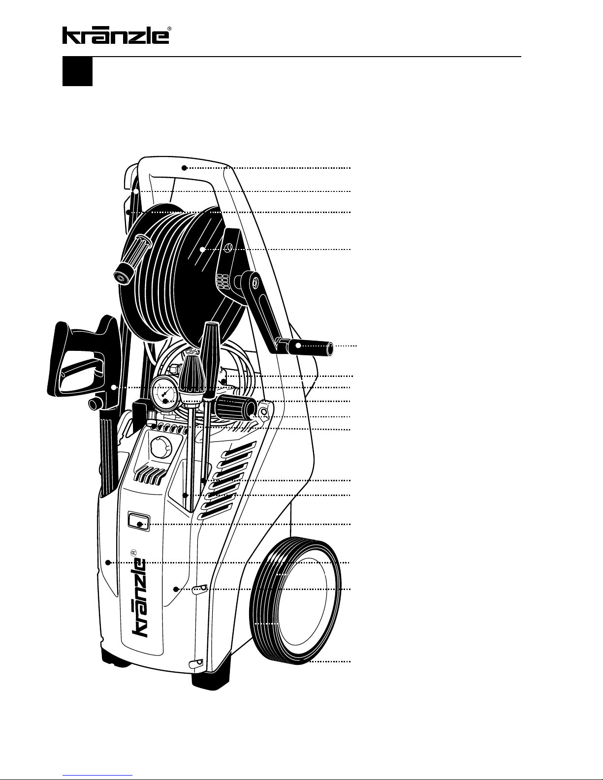
Description
Kränzle 2160 TS, 2160 TST,
Kränzle 2195 TS, 2195 TST,
Kränzle 2175 TS, 2175 TST
2
Ergonomically shaped handle
Cable reel with 5 m cable
Receptacle for gun with spray
lance (during breaks)
Generously dimensioned hose
drum with 15 m steel braided highpressure hose
(only available for TST models)
Hand crank (only available for TST
models)
Ergonomically shaped handle
High-pressure gun
Large stainless steel manometer
Fully adjustable pressure control
Detergent hose
with filter
Interchangeable lance with Dirtkiller nozzle
Interchangeable washing lance
On/Off switch with signal lamp and motor
protection
Receptacle for high-pressure gun
Receptacle for Dirtkiller and lance
Generously dimensioned trolley
suited for difficult terrain and stairs
Page 3

Description .......................................................................................... 2
Contents .......................................................................................... 3
Technical data ........................................................................................ 4
Overview “This is what you have purchased” ........................................... 6
General rules ......................................................................................... 7
Safety precautions – accident prevention ................................................ 8
Extremely important: Water connection – electrical connection ............. 10
Kränzle- technology
................................................................................. 12
Water and cleaning system ................................................ 12
Lance and spray gun ......................................................... 12
Pressure control valve – safety valve ................................. 12
Motor protecting switch ..................................................... 13
High pressure hose and spray device ....................................... 13
Total stop system .............................................................. 13
Putting into operation ........................................................................ 14
Connection to water mains ................................................ 14
Direct suction ................................................................... 17
When using detergents ..................................................... 18
To shut down the pump / frost protection ............................................... 19
Small repairs – do it yourself! ............................................................... 20
Inspections – inspection reports ............................................................ 24
EG – Declaration of Conformity ............................................................ 26
Guarantee ........................................................................................ 27
Accessories for high-pressure cleaners ................................................. 28
Spare parts list ................................................................................... 30
Complete assembly ........................................................... 30
Valve housing ................................................................... 32
Unloader valve and pressure switch .................................. 34
Motor ................................................................................ 36
Transmission .................................................................... 38
Hose drum ........................................................................ 39
Gun with lance .................................................................. 40
Dirtkiller with lance ........................................................... 41
Wiring diagrams ................................................................................... 43
Contents
Page
3
Page 4
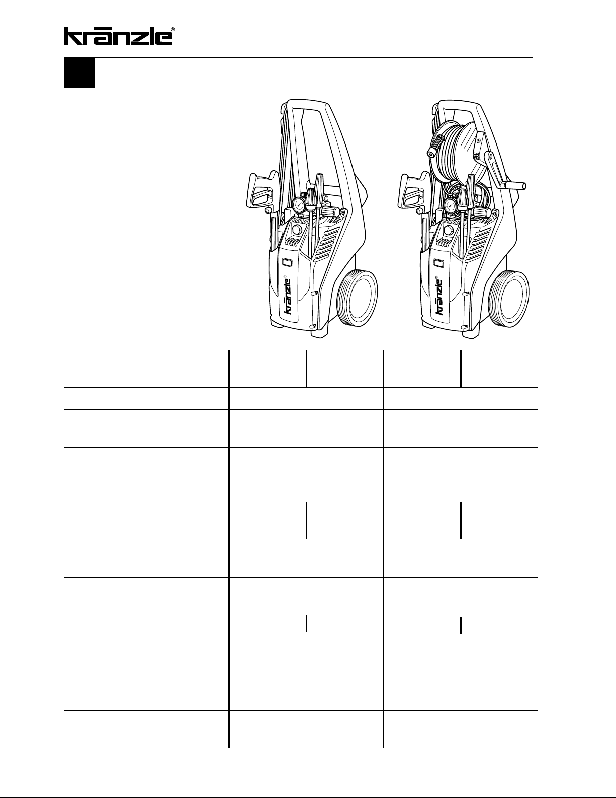
4
Operating press. fully adjustable
30 - 140 bar 30 - 180 bar
Nozzle size 25045 25030
Permissible overpressure 160 bar 195 bar
Water output at
1,400 r.p.m. 11 l/min
at
1,400 r.p.m. 8 l/min
Water inlet temperature max. 60 °C max. 60 °C
Suction height 2.5 m 2.5 m
Hose drum no yes no yes
Steel braided high-pressure hose
10 m 15 m 10 m 15 m
Detergent suction yes yes
Connected load
230 V~ 50 Hz, 14 A 230 V~ 50 Hz, 14 A
Power input P 1 - 3.2 kW P 1 - 3.2 kW
Power output P 2 - 2.4 kW P 2 - 2.4 kW
Weight 37 kg 39,5 kg 37 kg 39.5 kg
Dim. incl. pulling handle in mm 900 x 375 x 360 900 x 375 x 360
Sound level acc. to DIN 45 635 78 dB (A) 81 dB (A)
Sound level with Dirtkiller
82 dB (A) 78 dB (A)
Acoustic power LWA 89 dB (A) 91 dB (A)
Recoil at lance approx. 25 N approx. 25 N
Vibration at lance
2.0 m/s
2
2.0 m/s
2
Kränzle Kränzle Kränzle Kränzle
2160 TS 2160 TS T 2195 TS 2195 TS T
Technical data
Permissible tolerance for figures ± 5 % acc. to VDMA uniform sheet 24411
Page 5
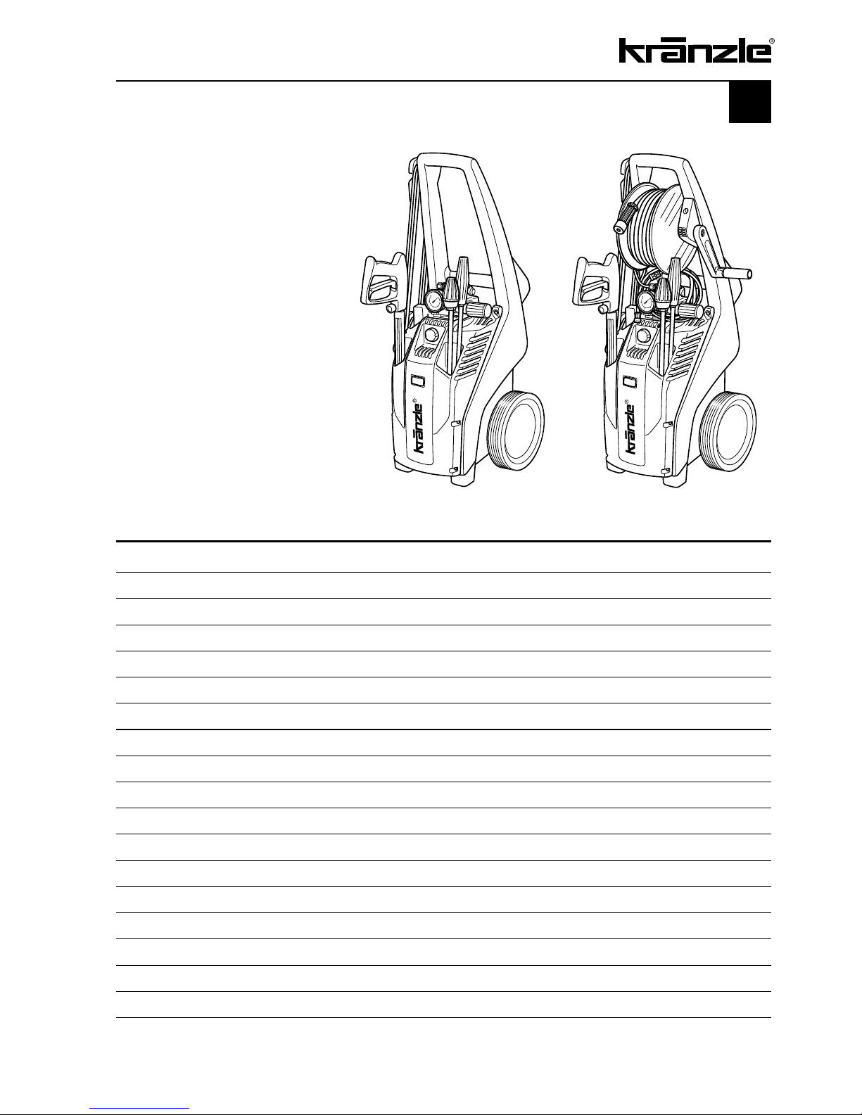
5
Operating press. fully adjustable 30 - 160 bar 30 - 160 bar
Nozzle size 25045 25045
Permissible overpressure 175 bar 175 bar
Water output
at 1,400 r.p.m. 12 l/min
at 1.400
r.p.m.
12
l/min
Water inlet temperature max. 60 °C max. 60 °C
Suction height 2.5 m 2.5 m
Hose drum no yes
Steel braided high-pressure hose 10 m 15 m
Detergent suction yes yes
Connected load
400 V~ 50 Hz, 6,7 A 400 V~ 50 Hz, 6,7 A
Power input P 1 - 3.3 kW P 1 - 3.3 kW
Power output P 2 - 2.6 kW P 2 - 2.6 kW
Weight 37 kg 39,5 kg
Dim. incl. pulling handle in mm 900 x 375 x 360 900 x 375 x 360
Sound level acc. to DIN 45 635 78 dB (A) 78 dB (A)
Sound level with Dirtkiller 82 dB (A) 82 dB (A)
Acoustic power LWA 91 dB (A) 91 dB (A)
Recoil at lance approx. 27 N approx. 27 N
Vibration at lance 2.1 m/s
2
2.1 m/s2
Kränzle 2175 TS Kränzle 2175 TS T
Permissible tolerance for figures ± 5 % acc. to VDMA uniform sheet 24411
Page 6
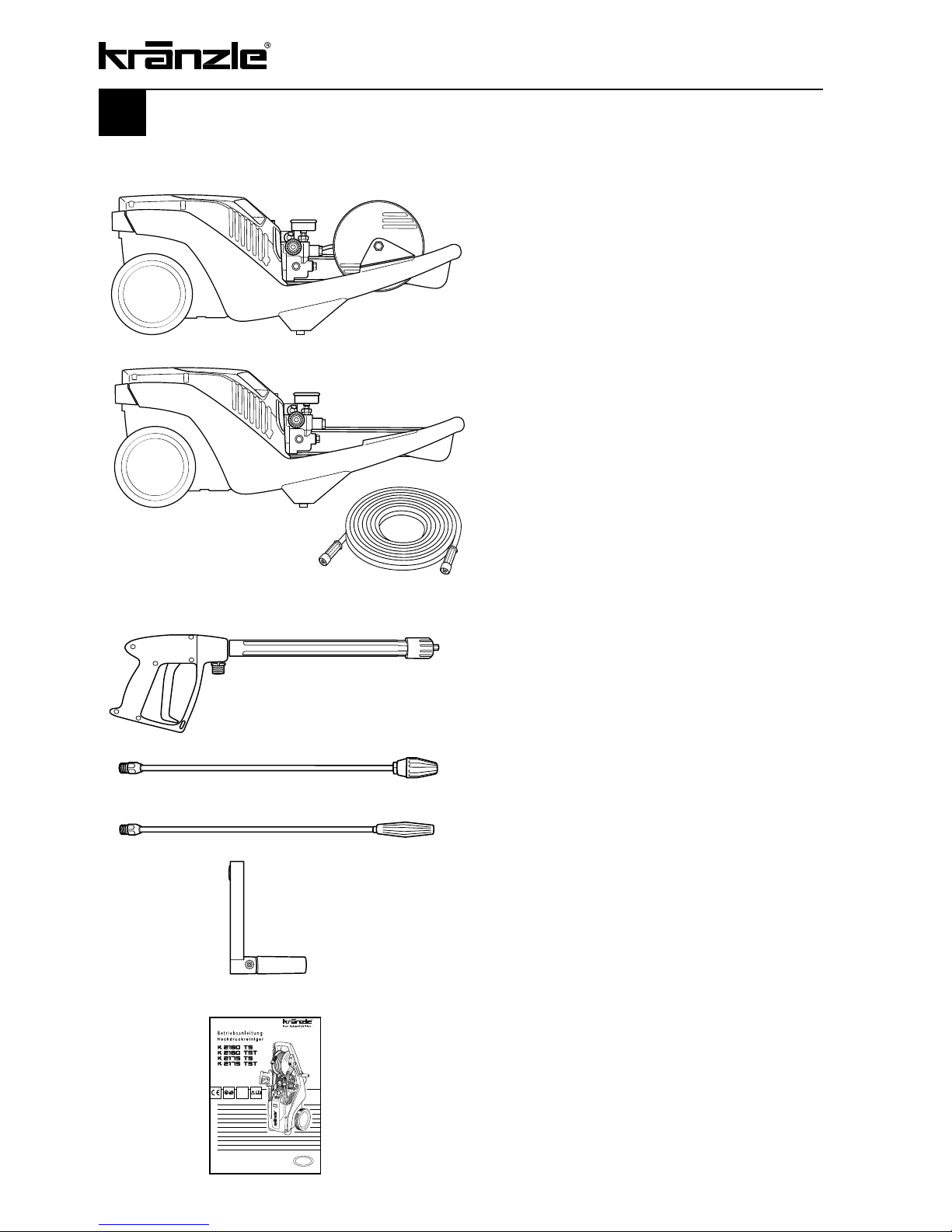
6
3.
Dirtkiller lance with stainless steel pipe
This is what you have purchased
1. Kränzle high-pressure cleaners
2160 TST, 2195 TST, 2175 TST with 15 m
steel braided high-pressure hose and hose
drum NW 6
or
2.
Trigger gun with safety catch, insulated
handle and screw connection
4.
Vario-Jet lance with stainless steel pipe
5
. Handle with fixing screw for hose drum
6.
Operating manual
Kränzle high-pressure cleaners 2160 TS,
2195 TS, 2175 TS with 10 m steel braided
high-pressure hose but without hose drum
NW 6
Page 7

7
General rules
Range of application
Use machines for cleaning tasks with high-pressure water jet and detergents or with
high-pressure water jet without detergents only.
Inspections
The machine must be inspected according to the “Guidelines for Liquid Spray Devices”
at least once every 12 months by a qualified person, to ensure that continued safe
operation is guaranteed. The results of the inspection are to be recorded in writing.
This may be done in any form. For inspection reports see pages 22 - 25.
High-pressure cleaners used for commercial purposes have to
be checked by a qualified person at least every 12 months!
Accident prevention
The machine is designed for accidents to be impossible if used correctly.The operator is
to be notified of the risk of injury from hot machine parts and the high pressure water jet.
The “Guidelines for Liquid Spray Devices” must be complied with. (see pages 8 and 9).
Oil change:
The first oil change should be carried out after approximately 50 operating hours,
then every year or after 1000 operating hours. If the oil turns grey or white, you must
change the oil of your high pressure pump in any case.
Put the machine into a horizontal position, then open the oil discharge screw at the
bottom of the device over a collection reservoir. The oil is to be caught in the reservoir
and disposed of in an approved manner.
New oil: 0,5 l - Motor oil W 15/40.
Oil leakage: If oil leaks contact your nearest after-sales
service (dealer) at once. (Ecological damage, damage to
the transmission)
In case of increased humidity or fluctuations in
temperature development of condensed water is
possible; if the oil turns grey, you must change it.
Page 8
8
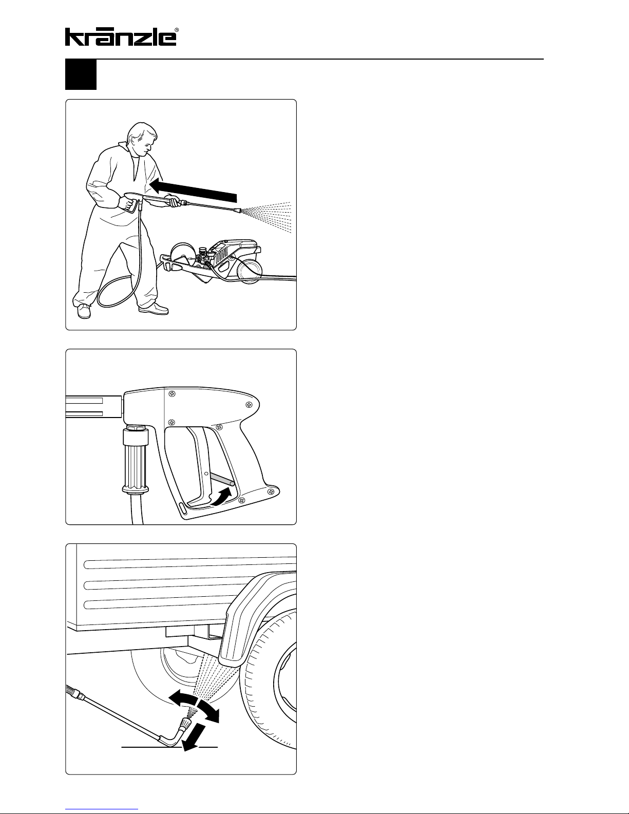
Safety precautions
Bear in mind that during cleaning tasks
with a high-pressure water jet a significant
recoil at the lance arises (see technical
data on page 4).
Apply the safety catch on the trigger
gun after each use, in order to prevent
unintentional spraying!
Always aim the underbody lance! Bear
in mind when using a curved or angled
spraying lance that there is a significant
amount of torque in the recoil!
Page 9
9
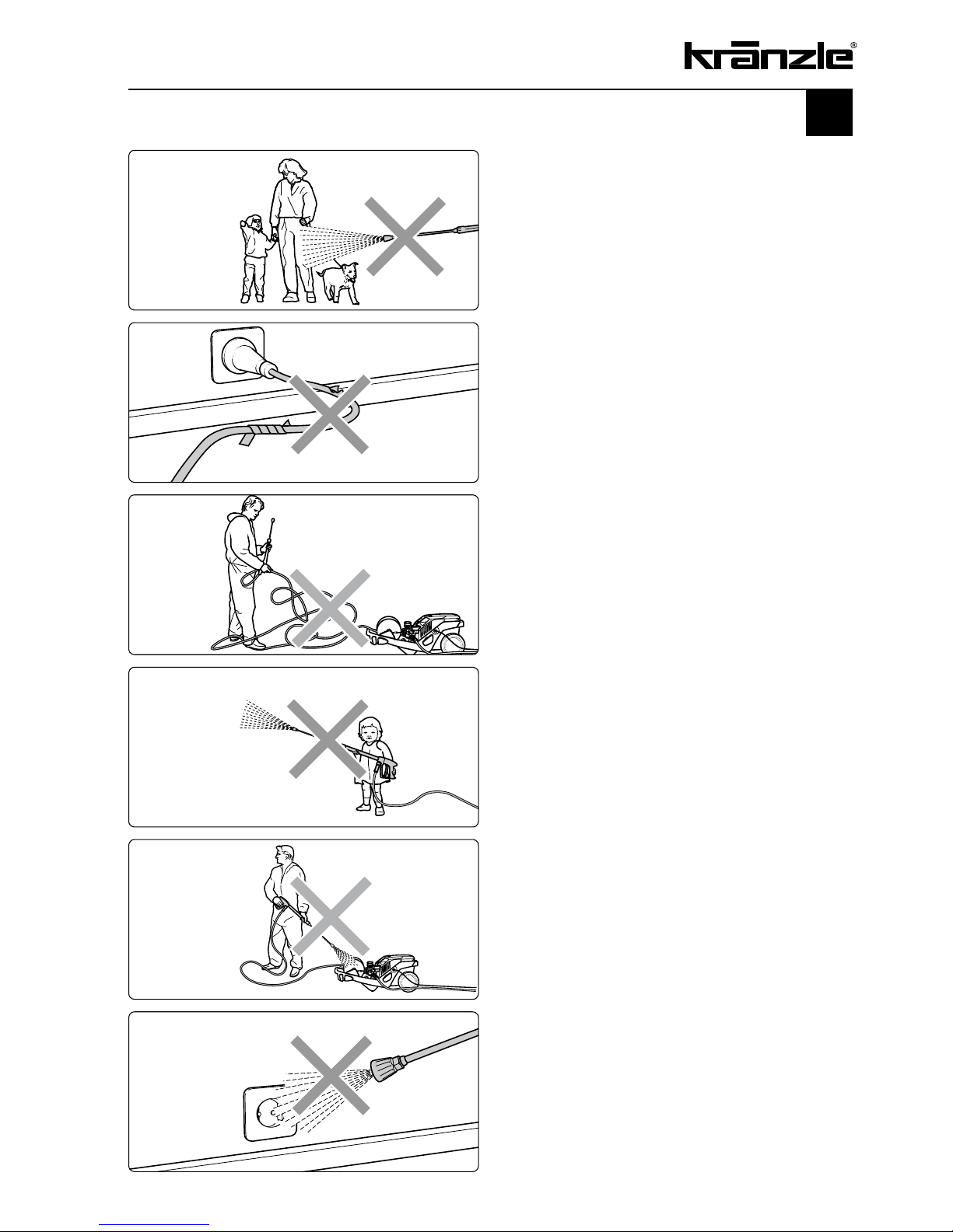
Safety precautions
- That`s forbidden!
Never allow children to use the
high pressure cleaner!
Never direct the water jet at the
machine itself!
Never direct the water jet at a
power socket!
Never direct the water jet at people
or animals!
Only use power cables which are
in perfect working order! Do not
damage the power cable or repair it
incorrectly!
Never pull the high pressure hose
if it has formed kinks or “nooses”!
Never pull the hose over sharp
edges!
Page 10
10
Please note - important!
Lack of water
If the metered quantity of water is too small, you have to use a different
water connection, guaranteeing the necessary output.
Lack of water leads to an accelerated wear of the joints (no guarantee).
The following minimum quantity of water is necessary for a safe and problem-free
operation of the high-pressure cleaner
:
Kränzle 2160 TS / TS T: 11 l/min
Kränzle 2195 TS / TS T: 8 l/min
Kränzle 2175 TS / TS T: 12 l/min
Connection to water supply
Please pay attention to the regulations of your waterworks company! In accordance
with DIN EN 61770, the machine may not be directly connected to the public drinking
water supply lines. A brief connection however is permissible according to DVGW
(German Association for Gas and Water Affairs) if a tube ventilator with check valve
(Kränzle Order-No. 41.016 4) is built into the water supply. Also indirect connection
to the public drinking water supply lines is permissible by way of free emission in
accordance with EN 61 770; e.g. by using a reservoir with a float valve.
Direct connection to a non-drinking water supply line is permissible.
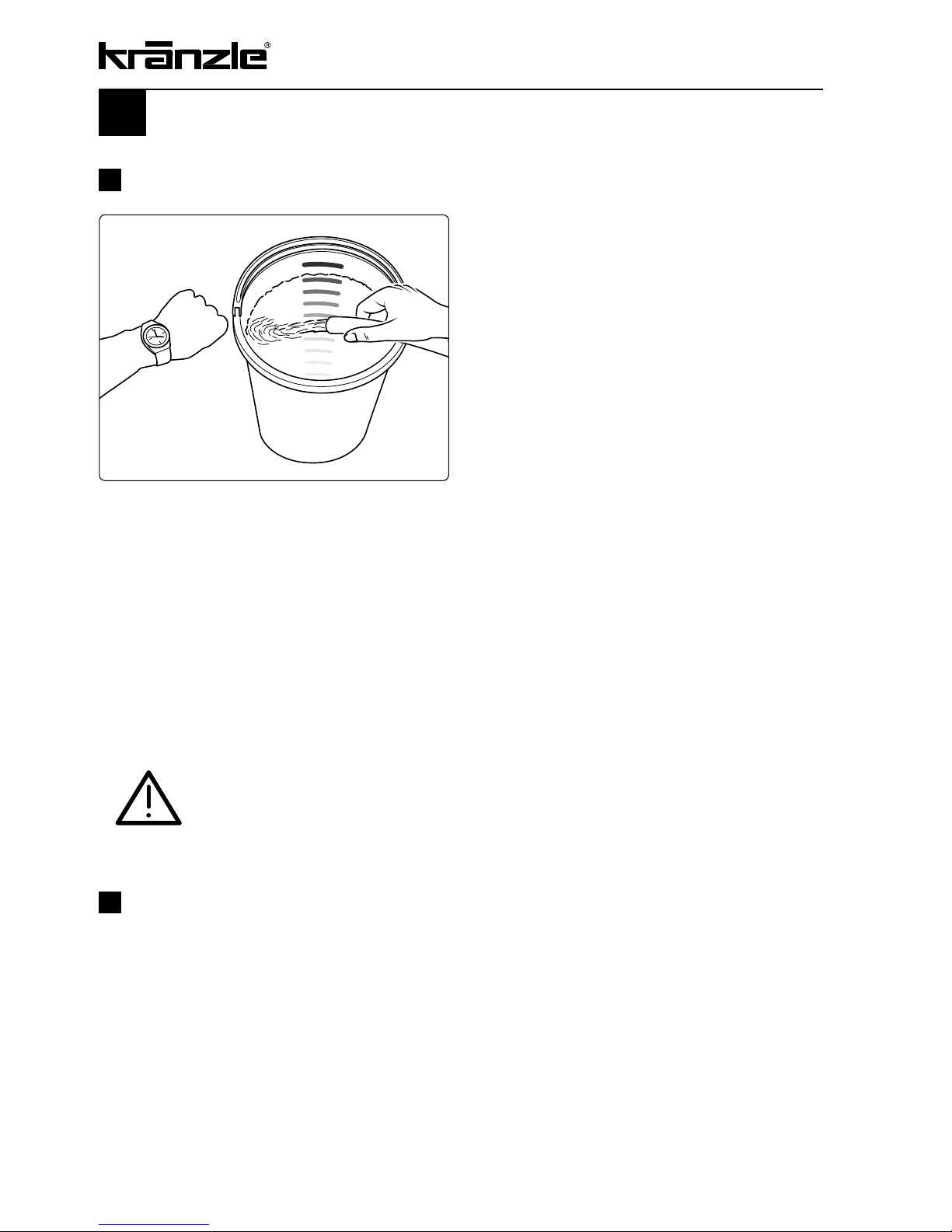
Lack of water occurs more often than you
probably believe. The more powerful a
high-cleaner is the greater is the danger
that a lack of water occurs. If there is only
an insufficient amount of water available,
cavitation arises inside the pump, which is
normally noticed too late or even not at all.
The pump will be destroyed!
Please check the available quantity of
water by filling a bucket with litre scale for
one minute.
Page 11
Electrical connection
The machine is supplied with an electrical power cable with plug. The mains plug must
be fitted to a standard grounded socket with a 30mA residual current operated device.
The socket must be protected with a 16A delay action fuse on the mains side. When
using an extension cable, this must have an earthed lead which is properly connected to
the socket. The conductors in the extension cable must have a minimum cross section of
1.5 mm². Plug connections must be of a spray-proof design, and may not be located on
a wet floor. With extension cables of more than 10 m the minimum cross section must be
2.5 mm! When using a cable drum, always keep the cable wound as far as possible.
Check the line fusing and have the voltage and the available current
intensity checked by an expert in case of uncertainty.
11
Connected load:
Kränzle 2160 TS / TS T: 230 V ~, 50 Hz
Kränzle 2195 TS / TS T: 230 V ~, 50 Hz
Kränzle 2175 TS / TS T: 400 V, 50 Hz (phase-sequence not significant)
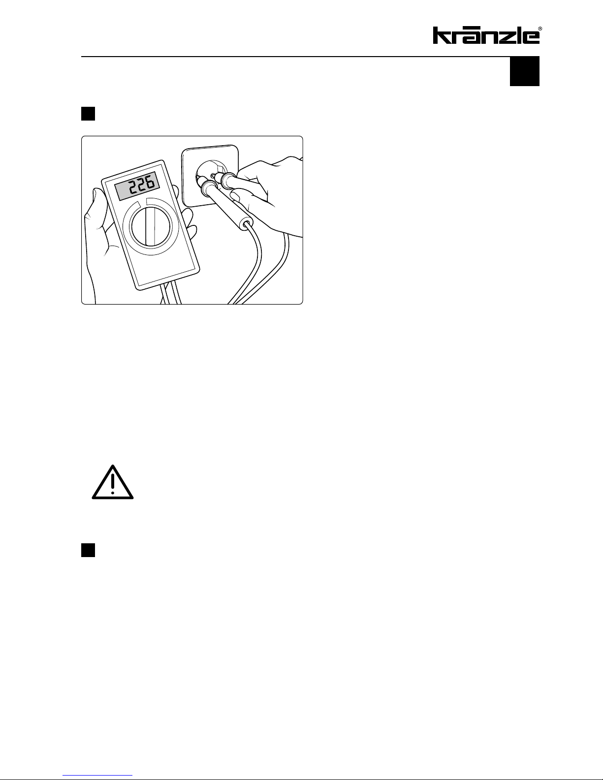
Insufficient quantity of electricity
If there are too many collectors in your
proximity connected to the network at
the same time, the available voltage
and the current intensity may decline.
Consequently the motor of the
high-pressure cleaner does not start or
even blows.
The power supply may also be insufficient
if the power cable is too long or too
thin. If extension cables are too long,
this may lead to a voltage drop causing
malfunctions or start-up difficulties.
Page 12

12
Kränzle technology
Water and Cleaning System
Water can be connected at mains pressure to the high pressure pump or it can be
sucked directly from a storage tank. The water is then forced under pressure by the high
pressure pump to the lance. The high pressure jet is formed by the nozzle at the end of
the lance.
Environmental, refuse disposal and water protection
regulations must be observed!
Lance with trigger gun
The machine can only be operated when the safety trigger is squeezed. When the
lever is squeezed, the spray gun opens. The liquid is then pumped to the nozzle. The
spray pressure increases and quickly reaches the selected operating pressure. When
the trigger is released, the trigger gun closes and any further spraying of liquid from the
lance is stopped. The pressure gauge must show 0 bar.
The increase in pressure when the trigger gun is closed causes the pressure control
valve-safety valve to open. The motor is switched off by the pressure switch. When
the trigger gun is opened, the pressure control valve - safety valve closes, the motor
is started and the pump resumes pressure spraying from the lance with the selected
operating pressure.
The trigger gun is a safety device. Repairs should only
be performed by qualified persons. Should replacement
parts be required, use only components authorized by
the manufacturer.
Pressure control valve - safety valve
The pressure control valve - safety valve protects the machine from a build up of
excess pressure, and is designed not to permit an excess pressure to be selected for
operation. The limit nut on the handle is sealed with a spray coating. The operating
pressure and spray rate can be steplessly adjusted by turning the handle
.
Replacements, repairs, new adjustments and sealing
should only be performed by qualified persons.
Page 13
13
Motor protection switch
The motor is protected from overload by a motor protection switch, which cuts out the
motor in the event of overload. However should the switch trip frequently, the cause of
the malfunction should be located and rectified (see page 11).
Replacements and inspection work should only be performed
by qualified persons when the machine is disconnected from
the power supply, i.e. with plug pulled out from the electrical
socket.
High pressure hose and spray device
The high pressure hose and spraying device supplied with the machine are made of high
grade material, they are also optimised for the machine and marked as required by the
appropriate regulations.
If replacement parts are required, only such parts that are
authorised by the manufacturer and which bear the markings
required by the appropriate regulations may be used. The
high pressure hose and spray device must be connected in
a pressure-tight manner. The high pressure hose may not be
driven over, pulled excessively, or twisted. The hose may under
no circumstances be pulled over sharp edges, since otherwise
the guarantee is automatically void.
Total stop system
The new Kränzle K2160 / K2195 / K2175 are equipped with an electrical Start/Stop
control. Having connected the high-pressure cleaner to the water supply and having
connected the HP hose, switch the machine “on” using the On/Off switch. A red light in
the switch flashes.
The motor is started by opening the gun. The motor is switched off after the gun has
been closed. The high-pressure cleaner works in stand-by until the On/Off switch is
switched to “Off”. The red light in the switch goes out.
Having switched off the machine shortly press the trigger to release the pressure to be
able to unfasten the HP hose.
Page 14
Setting up – Location
Neither set up or operate the machine in rooms where there
is a risk of fire or explosion nor put it into puddles. Do not
use the machine under water.
14
Putting into operation
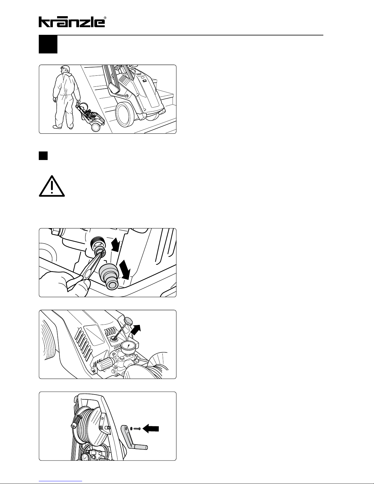
4.
Put up machine. Release fixing screw
from hexagonal base of hose drum, put
tiltable handle onto the hexagonal base
and fix with screw.
2.
Check water inlet filter for
cleanliness prior to putting the machine
into operation!
Manually unscrew hose attachment. Take
out the serial water inlet filter using needle
nose pliers and clean if filter is soiled.
1.
Move high-pressure cleaner to the
job site.
The Kränzle 2160 / 2195 / 2175 are
movable machines with sturdy trolleys
ideally suited for difficult terrain and stairs.
Never pull the machine if the water
supply hose is still connected!
3
. Each time check oil level at the oil
dipstick prior to putting the HP cleaner
into operation. (Take care that cleaner is
in horizontal position!)
The oil level must show between the two
markings.
Page 15
15
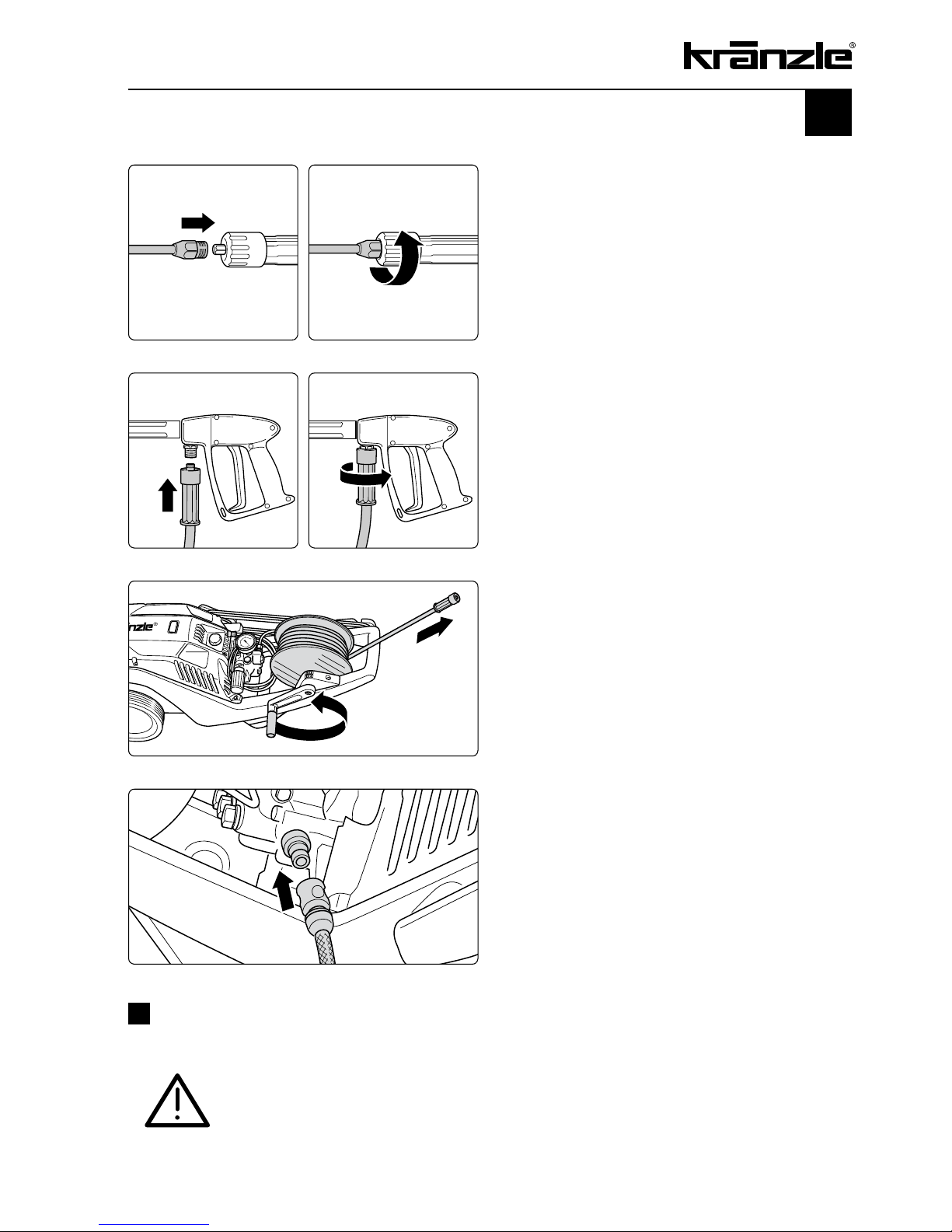
9.
Put HP cleaner into horizontal position.
These machines must be operated in
horizontal position! Unwind HP hose
from hose drum without kinks and nooses.
7.
Push on HP hose to gun.
8.
Screw together HP hose and gun.
10.
Connect water hose to water tank.
The cleaner may be connected to water
mains with cold or 60°C warm water.
Alternatively water can be sucked in from
a container (see page 17).
5.
Push on lance or Dirtkiller lance to gun.
6.
Screw together lance and gun.
Be careful when using hot water!
When running your high pressure cleaner with hot water
of 60° C raised temperatures occur. Do not touch the
metal parts of the cleaner without safety gloves!
Page 16

16
Putting into operation
12.
Steplessly adjust operating pressure
with handwheel. The maximum pressure is
adjusted ex work.
13.
Ventilation of the machine: Pull and
release the trigger several times.
Switch on high-pressure cleaner with
opened spray gun. Start cleaning task.
11.
Connect to circuit.
Kränzle 2160 TS / TS T: 230 Volt, 50 Hz.
Kränzle 2195 TS / TS T: 230 Volt, 50 Hz.
Kränzle 2175 TS / TS T: 400 Volt, 50 Hz.
The socket must be protected with a 16A
delay action fuse on the mains side.
Page 17

17
Direct suction
Due the suction capacity of its pump (up to 2.5 m suction height, max. hose length 3 m)
this high-pressure cleaner can suck in water for cleaning purposes from separate
containers or ponds.
Prior to starting the first suction the pump resp. the
suction hose has to be filled with water!
3.
Put filled suction hose into the
container and start the cleaning job.
Use clean water only!
Never suck in water containing
chlorine.
Note
Depending on the water quality it may occur after a prolonged standstill that the valves
get sticky. Consequently the machine cannot properly suck in water from a container.
In this case connect a hose with pressurized water to the pump inlet. Having started the
machine the pressurized water opens the valves and the machine resumes sucking in
water from the container. Now you can carry on with your cleaning task as usual.
F
1.
Mount suction hose with suction filter
(Kränzle accessories No. 15.038 3). When
using other hoses the inner cross section
of the hose must be at least 3/4” = 16 mm.
2.
Fill suction hose with water.
Page 18

The pH value neutral 7-9 is prescribed for the detergents.
Only use detergents suitable for high-pressure cleaners.
Observe specifications of detergent manufacturer!
e.g.: protective equpment, rules for waste water treatment
etc.
Never suck in liquids containing solvents like varnish
solvents, petrol, oil or similar liquid! Observe specifications
of detergent manufacturers! Seals inside the appliance are
no resistant against solvents! The spray mist of solvents is
highly inflammable, explosive and poisonous
.
18
Suction of detergents
with detergent supply:
For the Kränzle
2160 TS / TS T, 2195 TS / TS T and 2175 TS / TS T a built-in injector
provides the facility to suck in detergents.
By pushing the Vario-Jet nozzle to the front the machine is adjusted to low pressure
and a vaccum is build up in the injector. Thus the detergent can be sucked in via the
connected suction hose with filter.
1.
Place chemicals filter into container
with cleansing agent.
2.
To reach the low pressure push Vario
nozzle to the front so that the injector can
suck in the cleansing agent.
3.
The chemicals supply is automatically
stopped when closing the Vario nozzle by
pushing it backwards.
Let cleansing agent take effect and then
spray off with a high-pressure jet.
Page 19

19
To shut down the pump
01.
Switch off the machine
02. Cut off the water supply
03. Open the spray gun briefly until the pressure is released
0
4. Apply the safety catch on the spray gun
05. Remove the water hose and spray gun
06. Drain the pump: switch on the motor for approx. 20 seconds
0
7. Pull the plug from the socket
08. Clean HP hose and wind up
09. Clean power cable and wind up
10. Clean water filter
11. Winter: store the pump in rooms above 0°C
Due to their compact and space saving
design these Kränzle-2000 cleaners can
be stored practically anywhere.
Store in a place-saving manner
Page 20

20
Small repairs -
do it yourself!
No water from the nozzle but the gauge shows full pressure:
Most likely the nozzle is blocked.
CAUTION! Pull plug from socket prior to starting
any repair work!
If this procedure is not successful, the nozzle has to be dismantled and cleaned or even
replaced, if necessary.
The pressure gauge shows full pressure,
but from the nozzle comes only little water
or no water at all.
(Inside the pressure gauge is no water but
a filling with glycol to damp the vibration of
the pointer.)
Switch off the cleaner. Pull plug from
the socket. Operate gun seveal times to
decrease the pressure.
First unscrew gun and lance, then rinse
hose from any residues.
Check water inlet filter for soiling.
If the problem still exists, take wire (paper
clip) and push through nozzle opening.
Page 21

Unscrew all 6 valves, one after the other
(hexagonal brass screws, 3 in a row,
vertically and horizontally)
21
Pressure gauge shows little pressure, the water from the nozzle comes
in squirts: Most likely the valves are soiled or sticky.
The pressure gauge shows little
pressure despite fully turned up pressure
regulation. The water from the lance
comes in squirts. The HP hose vibrates.
(Inside the pressure gauge is no water but
a filling with glycol to damp the vibration of
the pointer.)
Take out valve body (with green or red
plastic coating) and O-ring by means
of needle nose pliers. Check O-ring for
damage. In case of a damage the O-ring
has to be replaced.
Take a wire (paper clip) and clean valves
under running water. Also clean valve seat
inside the pump.
Do not forget the O-ring during
reassembly!
Page 22

22
Small repairs -
do it yourself!
The pressure gauge shows full pressure although the gun has
been closed. The pressure switch valve switches constantly.
Possible cause no.1: Leakage
Having closed th gun, the HP cleaner must
shut down and the pressure gauge must
show „0“ bar.
If the pressure gauge still shows full
pressure and the motor constantly
switches on and off, the possible reason
for this can be a leakage of the pump, the
HP hose or the lance.
Proceeding:
Check the connections from the HP cleaner to the the HP hose, from the hose to
the gun and also the connection between
lance and gun for tightness.
Switch off the cleaner. Shortly pull the trigger of the gun to decrease the
pressure.
Unscrew HP hose, gun and lance and
check the O-rings.
If the O-rings are damaged they have to
be replaced.
Caution!
In case of a leakage there is no guarantee for
possible consequential damages.
Page 23

23
Unscrew pump outlet.
Take out check ball and check for soiling
or damage of ball or stainless steel seat
inside the pump housing.
Replace non-return valve if necessary.
The pressure gauge shows full pressure although the gun has
been closed. The pressure switch valve switches constantly.
Possible cause no. 2: The return body is soiled
or the sealing ring on the return body is defective.
Caution !
There is no guarantee if the pump is damaged
by defective O-rings due to air induction or lack of water
(cavitation).
Page 24

24
Type plate (on hand)
Operating manual (on hand)
Protective covering, -device
Pressure line (tightness)
Pressure gauge (function)
Float valve (tightness)
Spraying device (marking)
HP-hose / connector (damage, marking)
Safety valve opens at 10 % / 20 % exceeding of operating pr.
Power cable (damage)
Protective conductor (connected)
On / Off switch
Used chemicals
Allowed chemicals
High-prsure nozzle
Operating pressure..................bar
Switch off pressure................bar
Conductor reist. not exceeded / value
Insulation
Leakage current
Gun locked
The appliance was checked by an expert according to the Guidelines for Liquid
Spray Equipment, the defects found have been rectified so that the Labour Safety can
be confirmed.
The appliance was checked by an expert according to the Guidelines for Liquid
Spray Equipment. The Labour Safety cannot be confirmed unless the defects found are
rectified by repair or replacement of the faulty parts
The next retest according to the Guidelines for Liquid Spray Equipment has to be carried
out by: Month Year
Place, date Signature
Inspection report for HP cleaners
HP cleaners for industrial use have to be checked by an expert every 12 months!
Inspection report on annually carried out Labour Safety Inspection (UVV) according to
the Guidelines for Liquid Spray Equipment. (This inspection sheet serves as proof for
the completion of the retest and must be kept carefully!)
Kränzle test seals: Order no. UVV200106
Scope of inspection o.k. yes no repaired
Inspection data determined value set value
Inspection result (tick)
Owner:
Address:
Type:
Serial no.:
Rep. order no.:
Page 25

25
Inspection report for HP cleaners
Type plate (on hand)
Operating manual (on hand)
Protective covering, -device
Pressure line (tightness)
Pressure gauge (function)
Float valve (tightness)
Spraying device (marking)
HP-hose / connector (damage, marking)
Safety valve opens at 10 % / 20 % exceeding of operating pr.
Power cable (damage)
Protective conductor (connected)
On / Off switch
Used chemicals
Allowed chemicals
High-prsure nozzle
Operating pressure..................bar
Switch off pressure................bar
Conductor reist. not exceeded / value
Insulation
Leakage current
Gun locked
The appliance was checked by an expert according to the Guidelines for Liquid
Spray Equipment, the defects found have been rectified so that the Labour Safety can
be confirmed.
The appliance was checked by an expert according to the Guidelines for Liquid
Spray Equipment. The Labour Safety cannot be confirmed unless the defects found are
rectified by repair or replacement of the faulty parts
The next retest according to the Guidelines for Liquid Spray Equipment has to be carried
out by: Month Year
Place, date Signature
HP cleaners for industrial use have to be checked by an expert every 12 months!
Inspection report on annually carried out Labour Safety Inspection (UVV) according to
the Guidelines for Liquid Spray Equipment. (This inspection sheet serves as proof for
the completion of the retest and must be kept carefully!)
Kränzle test seals: Order no. UVV200106
Scope of inspection o.k. yes no repaired
Inspection data determined value set value
Inspection result (tick)
Owner:
Address:
Type:
Serial no.:
Rep. order no.:
Page 26

Kränzle 2160 TS / TS T,
Kränzle 2195 TS / TS T,
Kränzle 2175 TS / TS T,
Manfred Bauer, Fa. Josef Kränzle
Rudolf-Diesel-Str. 20, 89257 Illertissen
machinery directive 2006/42/EEC,
EMC-directive 2004/108 EEC,
noise directive 2005/88/EC, Art. 13,
HP water spraying machines
annex 3, part B, chapter 27
Kränzle 2160 TS / TS T: 87 dB (A)
Kränzle 2195 TS / TS T: 87 dB (A)
Kränzle 2175 TS / TS T: 89 dB (A)
Kränzle 2160 TS / TS T: 89 dB (A)
Kränzle 2195 TS / TS T: 89 dB (A)
Kränzle 2175 TS / TS T: 91 dB (A)
annex V, noise directive 2005/88/EC
EN 60 335-2-79 :2004
EN 55 014-1 :2006
EN 61 000-3-2 :2006
EN 61 000-3-3 :2008
26
EC declaration of conformity
Hereby we declare that:
technical specifications available from:
comply with the following guidelines
and their amendments for high-pressure
cleaners:
Sound level measured:
Sound level guaranteed:
Applied conformity evaluation procedures
Applied specifications and standards:
I. Kränzle GmbH
Elpke 97 D - 33605 Bielefeld
Bielefeld, 21.12.2009
(Managing director)
Page 27

27
Guarantee
The guarantee is only valid for material and manufacturing errors.
Wearing does not fall within this gurantee.
The instructions in our operating manual must be complied with..
The operating instructions form part of the guarantee. The Guarantee is void if other parts
are used than genuine Kränzle accessory parts or genuine Kränzle spare parts.
For high-pressure cleaners sold to the user the guarantee period is 24 month.
For high-pressure cleaners sold for industrial use the guarantee period is 12 month.
In the case of a guarantee please contact your dealer or authorized seller delivering
accessories and your purchase receipt. You can fin them in the internet under
www.kraenzle.com.
The guarantee is also void if the machine is used with exceeding the temperature and
speed limits, a voltage below the required rating, with less than the required amount of
water or with dirty water.
Pressure gauge, nozzle, valves, sleeves, high pressure hose and spray equipment are
wear parts and are not covered by the warranty.
Page 28

28
Versatile due to Kränzle accessories
Rotating washing brush with 400 mm
extension, Order no. 41 050 1
Underbody lance with 800 mm extension,
Order no. 41 075
Pipe cleaning hose with nozzle,
10 m - Order no. 41 058 1
20 m - Order no. 41 058 2
25 m - Order no. 41 058 3
30 m - Order no. 41 058 4
Page 29

29
Sludge sucker, stainless steel,
Order no. 41 801
Sludge sucker with 3 m suction hose,
Order no. 41 104
Sand blasting set compl. up to 12 l/min, 150 bar
Order no. 41 068 1
Sand blasting set compl. up to bis 19 l/min, 250
bar Order no. 41 068
Floor cleaner round cleaner UFO
Order no. 41.850
Page 30

30
Spare parts list
Kränzle 2160 / 2195 / 2175
Page 31

31
Complete assembly
1 Motor-Pumpen-Einheit mit Elektrik
K 2160 TS 1 48.060
K 2160 TS T 1 48.061
K 2195 TS 1 48.062
K 2195 TS T 1 48.063
K 2175 TS 1 48.064
K 2175 TS T 1 48.065
1.1 Motor-Pumpen-Einheit ohne Elektrik
K 2160 TS 1 48.060 1
K 2160 TS T 1 48.061 1
K 2195 TS 1 48.062 1
K 2195 TS T 1 48.063 1
K 2175 TS 1 48.064 1
K 2175 TS T 1 48.065 1
2 Fahrgestell 1 48.000
3 Versteifungsblech 1 48.010
4 Schraube 6,0 x 30 6 43.423
5 Schraube M 8 x 12 4 40.122
6 Achshalter 1 48.003
7 Schraube M 6 x 40 2 48.012
8 Standfuß links + rechts 1 48.005
10 Käfigmutter M6 2 48.011
11 Schraube 5,0 x 30 2 43.418
12 Rad d210mm 2 44.538
13 Scheibe 40 x 6 x 1,5 (Stahl) 2 45.216 7
14
Kunststoffsenkschraube 5,0 x 20 2 45.421 1
15 Radkappe 2 46.011
16 Gummipuffer 20 x 25 2 48.013
17.1 Frontplatte „K 2160 TS“ 1 48.002 1
17.2 Frontplatte „K 2160 TS T“ 1 48.002 2
17.3 Frontplatte „K 2195 TS“ 1 48.002 3
17.4 Frontplatte „K 2195 TS T“ 1 48.002 4
17.5 Frontplatte „K 2175 TS“ 1 48.002 5
17.6 Frontplatte „K 2175 TS T“ 1 48.002 6
18 Knickschutz 1 48.004
19 Schraube 5,0 x 14 2 43.426
28 O-Ring 9,3 x 2,4 2 13.273
29 Hochdruckschlauch NW 6 10 m (TS-Geräte) 1 43.416
30 Midi-gun with extension 1 12.160
31.1
Vario-Jet
03 with lance 400 mm 1 41.156 2
for K 2195 TS / TST
31.2
Vario-Jet
045 with lance 400 mm 1 41.156
for K 2160 TS / TST + K 2175 TS / TST
32.1 Dirtkiller 03 with lance 400 mm 1 41.073 8
for K 2195 TS / TST
32.2 Dirtkiller 045 with lance 400 mm 1 41.072 5
for K 2160 TS / TST + K 2175 TS / TST
No Description Qty. Ord.-No
Page 32

32
Spare parts list
Kränzle 2160 / 2175
Page 33

33
Valve housing 18mm
No Description Qty. Ord.-No
1 Ventilgehäuse 1 42.160 3
2 Ventilstopfen 5 41.714
2.1 Ventilstopfen mit R1/4“ IG 1 42.026 1
3 Dichtstopfen M 10 x 1 1 43.043
4 Ventile (grün) für APG-Pumpe 6 41.715 1
5 O-Ring 16 x 2 6 13.150
6 O-Ring 15 x 2 6 41.716
7 Dichtstopfen R1/4” mit Bund 1 42.103
8 Ausgangsteil (TST) 1 40.522
8.1 Ausgangsteil (TS) 1 40.522 2
9 Dichtstopfen M 8 x 1 2 13.158
10 O-Ring 18 x 2 1 43.446
11 Aluminium - Dichtring 3 13.275
12 Verschraubung Ermeto R1/4” x 8 1 41.042
13 O-Ring 11 x 1,5 1 12.256
14 Edelstahlsitz Ø 7 1 14.118
15 Sprengring 1 12.258
16 Edelstahlkugel Ø10 1 12.122
17 Rückschlagfeder „K“ 1 14.120 1
27 Druckring 3 41.018
28 Manschette 18 x 26 x 4/2 3 41.013
28.1 Gewebemanschette 18 x 26 x 4/2 3 41.013 1
29 Backring 18 x 26 6 41.014
30 O-Ring 28,3 x 1,78 3 40.026
31 Leckagering 18 mm 3 41.066
32 Zwischenring 18 mm 3 41.015 2
33 Verschlussstopfen R3/8“ 1 14.113
34 Kupferring 17 x 22 x 1,5 1 40.019
37 Verschlussschraube M10x1 1 13.385
38 O-Ring 6x1,5 2 13.386
39 Saugzapfen Schlauchanschluss 1 13.236
40 Edelstahlkugel 5,5 mm 1 13.238
41 Edelstahlfeder 1 13.239
42 Kupferring 14 x 20 x 1,5 1 42.104
43 Innensechskantschraube M 8 x 30 2 41.036 1
44 Innensechskantschraube M 8 x 55 2 41.017 1
46 Sauganschluß 1 41.016
47 Wasserfilter 1 41.046 2
48 Gummi Dichtring 1 41.047 1
49 Steckkupplung 1 41.047 4
50 O-Ring 1 41.047 3
Reparatur-Sätze:
Reparatursatz Manschetten 18 mm 41.049 1
bestehend aus je
3 x Pos. 13; 6 x Pos. 14; 3 x Pos. 15; 3 x Pos. 23; 3 x Pos. 18
Reparatursatz Ventile für APG-Pumpe 41.748 1
bestehend aus je 6 x Pos. 4; 6 x Pos. 5; 6 x Pos. 6
Page 34

34
Spare parts list
Kränzle 2195
Page 35

35
Valve housing 15mm
No Description Qty. Ord.-No
1 Ventilgehäuse 1 42.163 3
2 Ventilstopfen 5 41.714
2.1 Ventilstopfen mit R1/4“ IG 1 42.026 1
3 Dichtstopfen M 10 x 1 1 43.043
4 Ventile (grün) für APG-Pumpe 6 41.715 1
5 O-Ring 16 x 2 6 13.150
6 O-Ring 15 x 2 6 41.716
7 Dichtstopfen R1/4” mit Bund 1 42.103
8 Ausgangsteil (TST) 1 40.522
8.1 Ausgangsteil (TS) 1 40.522 2
9 Dichtstopfen M 8 x 1 2 13.158
10 O-Ring 18 x 2 1 43.446
11 Aluminium - Dichtring 3 13.275
12 Verschraubung Ermeto R1/4” x 8 1 41.042
13 O-Ring 11 x 1,5 1 12.256
14 Edelstahlsitz Ø 7 1 14.118
15 Sprengring 1 13.147
15 Edelstahlkugel Ø10 1 12.122
17 Rückschlagfeder „K“ 1 14.120 1
27 Stützring rot 15mm 3 42.913
28 Manschette weich 15mm 3 42.902
28.1 Manschette Gewebe 15mm 3 42.902 1
29 Backring 15 x 24 6 42.903
30 O-Ring 28,3 x 1,78 3 40.026
31 Leckagering 15 mm 3 42.905
32 Zwischenring 15 mm 3 42.904 1
33 Verschlussstopfen R3/8“ 1 14.113
34 Kupferring 17 x 22 x 1,5 1 40.019
37 Verschlussschraube M10x1 1 13.385
38 O-Ring 6x1,5 2 13.386
39 Saugzapfen Schlauchanschluss 1 13.236
40 Edelstahlkugel 5,5 mm 1 13.238
41 Edelstahlfeder 1 13.239
42 Kupferring 14 x 20 x 1,5 1 42.104
43 Innensechskantschraube M 8 x 30 2 41.036 1
44 Innensechskantschraube M 8 x 55 2 41.017 1
46 Sauganschluß 1 41.016
47 Wasserfilter 1 41.046 2
48 Gummi Dichtring 1 41.047 1
49 Steckkupplung 1 41.047 4
50 O-Ring 1 41.047 3
Reparatur-Sätze:
Reparatursatz Manschetten 15 mm 42.911
bestehend aus je
3 x Pos. 13; 6 x Pos. 14; 3 x Pos. 15; 3 x Pos. 23; 3 x Pos. 18
Reparatursatz Ventile für APG-Pumpe 41.748 1
bestehend aus je 6 x Pos. 4; 6 x Pos. 5; 6 x Pos. 6
Page 36

36
Spare parts list
Kränzle 2160 / 2195 / 2175
No Description Qty. Ord.-No
70 Steuerkolben kpl. mit Handrad 40.490
71 Rep.- Satz Druckschaltermechanik 15.009 3
72 Druckschalter kpl. 41.300 6
73.1 Ventilgehäuse kpl. ohne Manometer (K2160 TS, K2175 TS) 48.050
73.2 Ventilgehäuse kpl. ohne Manometer (K2160 TST, K2175 TST) 48.050 1
73.3 Ventilgehäuse kpl. ohne Manometer (K2195 TS) 48.051
73.4 Ventilgehäuse kpl. ohne Manometer (K2195 TST) 48.051 1
Page 37

37
Unloader valve and pressure switch
No Description Qty. Ord.-No
5 O-Ring 16 x 2 1 13.150
5.1 O-Ring 13,94 x 2,62 1 42.167
8 O-Ring 11 x 1,44 1 12.256
9 Edelstahlsitz 1 14.118
10 Sicherungsring 1 13.147
11 Edelstahlkugel 1 13.148
12 Edelstahlfeder 1 14.119
13 Verschlussschraube 1 14.113
14 Steuerkolben 1 14.134
15 Parbaks 16 mm 1 13.159
16 Parbaks 8 mm 1 14.123
17 Spanstift 1 14.148
18 Kolbenführung spezial 1 42.105
19 Kontermutter M 8 x 1 2 14.144
20 Ventilfeder schwarz 1 14.125
21 Federdruckscheibe 1 14.126
22 Nadellager 1 14.146
23 Handrad AM-Pumpe 1 40.457
24 Kappe Handrad AM-Pumpe 1 40.458
25 Elastic-Stop-Mutter M 8 x 1 1 14.152
26 Manometer 0-250 Bar 1 15.039
27 Aluminium-Dichtring 2 13.275
40 Sechskant - Mutter M 4 2 12.138
42 Druckfeder 1 x 8,6 x 30 1 40.520
50 O-Ring 3,3 x 2,4 1 12.136
51 Führungsteil Steuerstößel 1 15.009 1
52 O-Ring 13 x 2,6 1 15.017
53 O-Ring 14 x 2 1 43.445
54 Parbaks 4mm 2 12.136 2
55 Stützscheibe 2 15.015 1
56 Edelstahlfeder 1 15.016
57 Steuerstößel 1 15.010 2
58 Parbaks 7mm 1 15.013
59 Stopfen M 10 x 1 (durchgebohrt) 1 13.385 1
60 Gehäuse Elektroschalter 1 15.007
61 Gummimanschette PG 9 1 15.020
62 Scheibe PG 9 1 15.021
63 Verschraubung PG 9 1 15.022
64 Kabel 2x 1,5 mm² 1 15.019 1
65 Blechschraube 2,8 x 16 6 15.024
66 Deckel Elektroschalter 1 15.008
67 O-Ring 44 x 2,5 1 15.023
68 Mikroschalter 1 15.018
69 Zylinderschraube M 4 x 20 2 15.025
Page 38

38
Spare parts list
Kränzle 2160 / 2195 / 2175
Page 39

39
Motor
No Description Qty. Ord.-No
1 Ölgehäuse für AP mit Deckel und Dichtung 1 46.530 2
3 Rotor mit Motorwelle 1 43.316
4 Passfeder 6 x 6 x 20 1 41.483 1
5 Motor-Lager B-Seite 6205 - 2Z 1 43.317
6 Motor-Lager Schulterlager 7304 1 41.027
7 Toleranzhülse 1 43.330 1
8 Öldichtung 25 x 35 x 7 1 41.024
9 Lüfterrad BG 90 1 43.319
10 Lüfterhaube BG 90 1 43.320
11 Flachdichtung 1 43.030
12 Innensechskantschraube M 6 x 30 4 43.037
13 Schelle für Lüfterrad mit Schrauben 1 43.454
15 Schraube M 4 x 12 10 41.489
16 Erdungsschraube kpl. 1 43.038
20 Schaltkasten 1 48.001
21 Deckel für Schaltkasten 1 44.512
22 Klemmrahmen mit Schalterabdichtung 1 43.453
23 Blechschraube 3,5 x 9,5 2 41.088
24 Dichtung für Deckel 1 44.522
25 Schraube 5,0 x 20 4 43.018
27 Kabelverschraubung PG 13,5 1 40.539
28 Gegenmutter für PG 13,5 1 44.253
29 Kabelverschraubung PG 11 1 41.419
30 Gegenmutter für PG 11 1 44.521
31 Lüsterklemme 3-polig 1 43.326
32 Blechschraube 2,9 x 16 1 43.036
Kränzle 2160 TS / TST, 2195 TS / TST:
2.1 Motorgehäuse mit Stator Wechselstrom 1 43.826
14.1 Kabel mit Stecker (Schuko) 1 41.092
18 Kondensator 70 µF 1 43.322
26.1 Schalter mit 14,5 A 1 41.111 6
40.1 Switch box, AC compl. Pos. 20 – 32 48.052
41.1 Motor, AC compl. without switch Pos. 1 - 16 48.054
Kränzle 2175 TS / TST:
2.2 Motorgehäuse mit Stator Drehstrom 1 43.827
14.2 Kabel mit Stecker (CE-KON) 1 43.828
21.2 Schraube 3,5 x 20 1 43.415
26.2 Schalter mit 11 A 1 41.751
33 Schütz 3x400V 50/60 Hz 1 48.016
34 Schraube 4,0 x 16 2 43.417
40.2 Switch box, threephase current, compl. Pos. 17, 19 – 31 48.053
41.2 Motor, threephase current, compl. without switch Pos. 1 - 16 48.055
Page 40

40
Transmission
No Description Qty. Ord.-No
1 Gehäuseplatte für 18 mm Plunger 1 41.020 2
2 Öldichtung 18 x 28 x 7 3 41.031
3 O-Ring Viton 88 x 2 1 41.021 1
4 Plungerfeder 3 41.033
5 Federdruckscheibe 18 mm 3 41.034
6 Plunger 18 mm 3 41.032 1
7 Sprengring 18 mm 3 41.035
8 Taumelscheibe 12,0° (K2160 TS / TST) 1 41.028-12,0
8.1 Taumelscheibe 13,0° (K2175 TS / TST) 1 41.028-13,0
10 Axial-Rillenkugellager 3-teilig 1 43.486
12 Innensechskantschraube M 8 x 30 4 41.036 1
13 Ölstopfen M18x1,5 1 41.011
14 O-Ring 14 x 2 3 43.445
15 Dichtung für Deckel 1 46.531
16 Deckel für Ölgehäuse 1 46.532
17 Schraube M5x12 4 41.019 4
18 Ölverschlussschraube mit Messstab 1 48.017
Page 41

41
Transmission
No Description Qty. Ord.-No
1 Gehäuseplatte für 15 mm Plunger 1 42.906
2 Öldichtung 15 x 24 x 7 3 42.907
3 O-Ring Viton 88 x 2 1 41.021 1
4 Plungerfeder 3 41.033
5 Federdruckscheibe 15 mm 3 42.909
6 Plunger 15 mm 3 42.908
7 Sprengring 15 mm 3 42.910
8 Taumelscheibe 14,3° (K2195 TS / TST) 1 41.028-14,3
10 Axial-Rillenkugellager 3-teilig 1 43.486
12 Innensechskantschraube M 8 x 30 4 41.036 1
13 Ölstopfen M18x1,5 1 41.011
14 O-Ring 14 x 2 3 43.445
15 Dichtung für Deckel 1 46.531
16 Deckel für Ölgehäuse 1 46.532
17 Schraube M5x12 4 41.019 4
18 Ölverschlussschraube mit Messstab 1 48.017
Page 42

42
Spare parts list
Kränzle 2160 / 2195 / 2175
Page 43

43
Hose drum
No Description Qty. Ord.-No
1 Seitenschale 2 48.101
2 Trommelteil 1 48.102
3 Knickschutz 1 40.162
4 Kunststoffschraube 5,0 x 20 5 43.018
5 Antriebswelle 1 48.104
7 Lagerklotz links 1 43.810
8 Schraube 6,0 x 30 4 43.423
9 Lagerklotz rechts 1 43.811
10 Verbindungsrohr 1 48.014
11 Wasser-Eingangsteil 1 48.103
12 O-Ring 6 x 0,8 2 40.177
13 Handkurbel 1 40.165
14 Schraube M 5 x 14 1 40.536
15 Scheibe 5,3 1 50.152
16 Wellensicherungsring 22 mm 2 40.117
17 O-Ring 9,3 x 2,4 1 13.273
18 Dichtsatz 1 13.410 1
19 Saugzapfen Schlauchanschluss 1 13.236
20 Edelstahlkugel 5,5 mm 1 13.238
21 Edelstahlfeder 1 13.239
22 Eingangsinjektror 1 40.317
23 O-Ring 10 x 2 1 43.068
24 O-Ring 6,68 x 1,78 1 40.585
25 Hochdruckschlauch 15m NW6 1 48.015
26 Chemikaliensaugschlauch mit Filter 1 15.038
30 Hose drum compl., without HP-hose 48.100
Page 44

44
Gun ‘Midi’ with lance
5 Rohranschlußteil R1/4“ incl. Pos. 3, 4, 21 1 12.125
6 Scheibe 5,3 DIN9021 1 50.152
7 Abzug-Hebel kpl. 1 12.144 1
15 Rohr kunststoffumspritzt bds. R 1/4“ AG 1 15.004 2
16 Überwurfmutter ST 30 M22 x 1,5 IG 1 13.276 1
17 Außen-Sechskant-Nippel R 1/4“ IG 1 13.277 1
18 O-Ring 9,3 x 2,4 1 13.273
19 ST 30-Nippel M 22 x 1,5 1 13.363
20 Rohr 400 lang, bds. M12 x 1 1 15.002
21 Aluminium Dichtring 6 13.275 1
30 Klemmstück 1 41.155 2
31 Halterung für Klemmstück 1 41.155 4
32 Kunstoffhülle 1 41.155 1
33 Vario-Jet 03 (K 2195) 1 41.155 9
33.1 Vario-Jet 045 (K 2160, K 2175) 1 41.155 6
A Rep.-Kit 12.158
Pos: 3, 4, 5, 8, 9,10, 12, 15, 21
B Handle, complete 12.164
Midi-gun compl. 12.160
Lance compl. with Vario-Jet 03 (K 2195) 41.156 2
Lance compl. with Vario-Jet 045 (K 2160, K 2175) 41.156
No Description Qty. Ord.-No
Page 45

45
Dirtkiller with lance
1 Sprühkörper 1 41.520
2 O-Ring 6,88 x 1,68 1 41.521
3 Düsensitz 1 41.522
4 Düse 03 1 41.523 4
4.1 Düse 045 1 41.523
5 Stabilisator 1 41.524
6 O-Ring 1 40.016 1
7 Sprühstopfen 1 41.526
8 Rohr 400 mm 2x M 12 x 1 1 41.527
9 ST 30-Nippel M 22 x 1,5 / M 12 x 1 ISK 1 13.363
11 Kappe vorn für Schmutzkiller 1 41.528 1
12 Kappe hinten für Schmutzkiller 03 1 41.542 1
12.1 Kappe hinten für Schmutzkiller 045 1 41.540 2
Rep.-Satz Schmutzkiller 03 41.096 1
Rep.-Satz Schmutzkiller 045 41.097
bestehend aus je 1x 2; 3; 4; 5
Schmutzkiller 03 kpl. mit Lanze 41.073 8
Schmutzkiller 045 kpl. mit Lanze 41.072 5
No Description Qty. Ord.-No
Page 46

46
Wiring diagram
Kränzle 2160 / 2195,
230 V, 50 Hz
On-Off switch with 14.5 Ampere
overload protection
Pressure switch
Pump motor
230 V / 50 Hz
Inlet line via
3 x 1,5 mm
2
,
230 V / 50 Hz
Page 47

47
On-Off switch with 11 Ampere
overload protection
Contactor
Inlet line via
CEE 4 x 1,5 mm²
400 V / 50 Hz
Pump motor
3 x 400 V / 50 Hz
Pressure switch
Wiring diagram
Kränzle 2175,
400 V, 50 Hz
Page 48

I . K r ä n z l e G m b H
E l p k e 9 7
D - 3 3 6 0 5 B i e l e f e l d
R e p r i n t o n l y a l l o w e d w i t h t h e a u t h o r i s a t i o n o f K r ä n z l e .
A s d a t e o f 1 0 . 0 3 . 2 0 1 0
S u b j e c t t o t e c h n i c a l mo d i f i c a t i o n s . O r d e r no . 3 0 . 7 9 0 1
K r ä n z l e – w o r l d - w i d e :
Te c h n i c a l p e r f e c t i o n , t o p d e s i g n .
 Loading...