

Page 1

High Pressure Cleaners
Operating manual
Read and conform
safety instructions
before use
GB
K
K
K
K
Page 2

2
Dear Customer
Permissible tolerance for figures ± 5 % in acc. with VDMA uniform sheet 24411
Min. water quantity to be supplied to the high pressure cleaner! (1 - 8 bar admission
pressure) (see page 7)
Description
- facades
- flagstones
- terraces
- vehicles of all types
- sheds
- channels
- barrels and containers
- machines etc.
We would like to congratulate you on your new high pressure cleaner with integrated
undercarriage and integrated hose drum and to thank you for the purchase.
To ease your introduction to the use of the cleaner, we have provided the following
pages of explanations, tips and hints, which we ask you to read before using for the
first time.
The equipment will assist you professionally in all cleaning tasks, e.g.:
Technical
specifications
Operating pressure,
steplessly adjust.
Perm. overpressure
Water output
Hot water input
Suction height
High pressure hose
Electrical ratings
Connect. wattage
input
output
Weight
Dim. with mounted
handle in mm
Sound level acc.to 45635
with dirtkiller
Guaranteed sound
level L
WA
Recoil at lance
Vibrations at lance
Ord.-No
with dirtkiller
Kränzle
115
10 - 115 bar
130 bar
at1400 rpm
10,3 l/min
max. 60 °C
2,5 m
10 m
230 V ; 50 Hz ;
11 A
P1: 2,6 kW
P2: 1,9 kW
32 kg
350 x 330 x 900
78 dB (A)
82 dB (A)
89 dB (A)
ca. 20 N
2,0 m/s²
41.204
41.204 1
Kränzle
125
10 - 125 bar
140 bar
at 1400 rpm
10,5 l/min
max. 60 °C
2,5 m
10 m
230 V ; 50 Hz ;
12,5 A
P1: 2,9 kW
P2: 2,2 kW
32 kg
350 x 330 x 900
78 dB (A)
82 dB (A)
89 dB (A)
ca. 22 N
2,0 m/s²
41.200
41.200 1
Kränzle
135
10 - 135 bar
150 bar
at1400 rpm
1 1,0 l/min
max. 60 °C
2,5 m
10 m
230 V ; 50 Hz ;
13,5 A
P1: 3,3 kW
P2: 2,4 kW
32 kg
350 x 330 x 900
78 dB (A)
82 dB (A)
91 dB (A)
ca. 25 N
2,0 m/s²
41.201
41.201 1
Kränzle
155
10 - 155 bar
170 bar
at 1400 rpm
12 l/min
max. 60 °C
2,5 m
10 m
400 V ; 50 Hz ;
6,7 A
P1: 4,1 kW
P2: 3,1 kW
32 kg
350 x 330 x 900
78dB (A)
82 dB (A)
91 dB (A)
ca. 27 N
2,1 m/s²
41.202
41.202 1
*
Page 3
3
98
2
Water
7
4
5
3
6
1
400 V
230 V
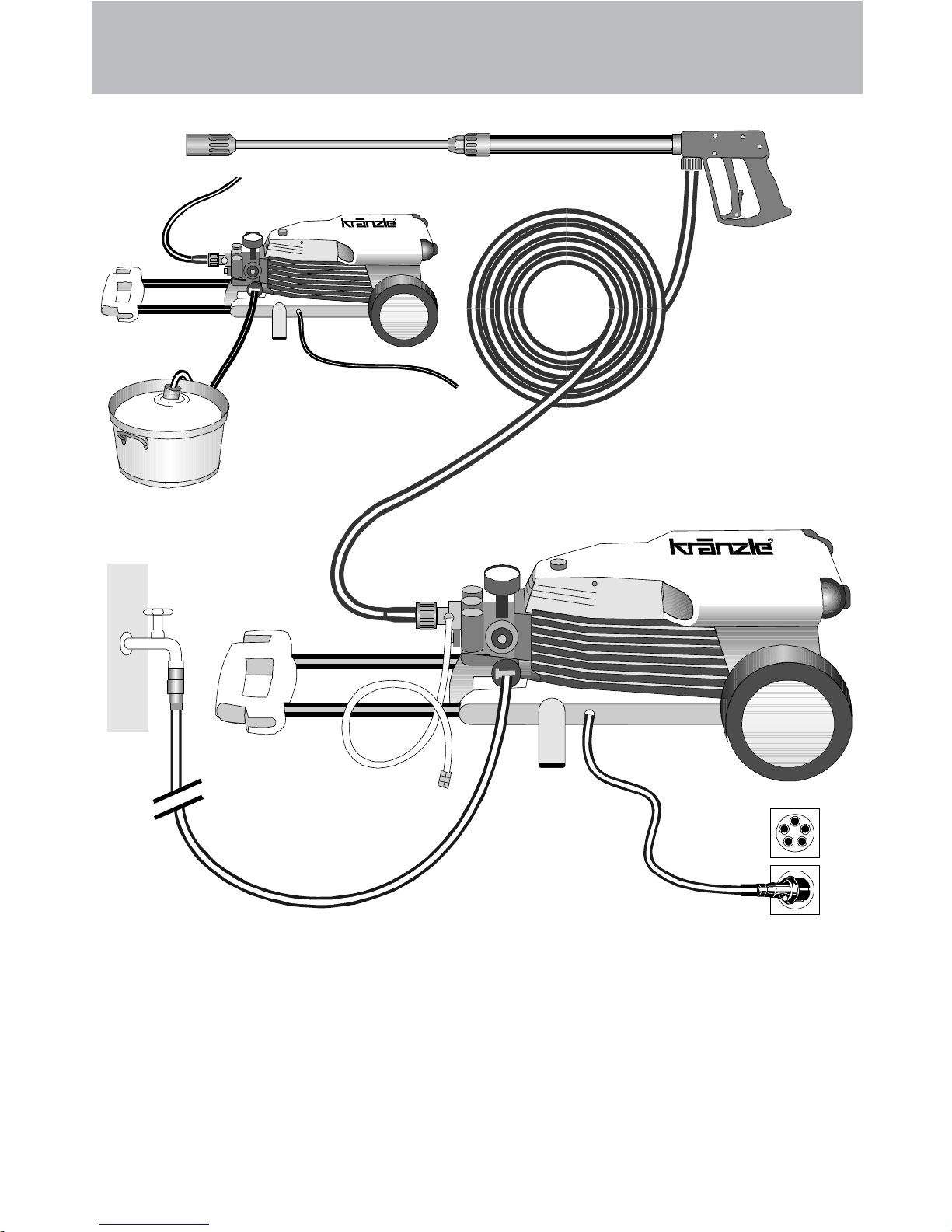
Construction
Description
The KRÄNZLE 115 + 125 + 135 + 155 - high pressure cleaners are mobile
machines. The design can be seen from the diagram.
Item
1 Water inlet connection with filter
2 Suction hose with filter (special
accessory) Order no. 15 038 3
3 High pressure pump
4 Press. gauge with glycerin filling
5 Unloader valve - safety valve
6 High pressure injector for
cleaning agents
7 High pressure hose
8 Spray gun
9 Interch. lance with regulator
nozzle
Page 4

4
Water and Cleaning System
Water can be connected at mains pressure to the high pressure pump or it
can be sucked directly from a storage tank. The water is then forced under
pressure by the high pressure pump to the lance. The high pressure jet is
formed by the nozzle at the end of the lance.
Cleaning and caring agents can be mixed with the water by a
high pressure injector.
Environmental, refuse disposal and water
protection regulations must be observed !
Lance with trigger gun
The machine can only be operated when the safety trigger is squeezed.
The machine can only be operated when the safety trigger is squeezed.
When the lever is squeezed, the spray gun opens. The liquid is then
pumped to the nozzle. The spray pressure increases and quickly reaches
the selected operating pressure.
When the trigger is released, the trigger gun closes and any further spraying
of liquid from the lance is stopped.
The increase in pressure when the trigger gun is closed causes the unloader
valve-safety valve to open. The pump remains switched on and continues to
pump liquid through the pump at reduced pressure. When the trigger gun is
opened, the unloader valve - safety valve closes and the pump ressumes
pressure spraying from the lance.
The trigger gun is a safety device. Repairs should only be performed by qualified persons. Should replacement parts be
required, use only components authorized by the manufacturer.
Unloader valve - safety valve
The unloader valve - safety valve protects the machine from a build p of
excess pressure, and is designed not to permit an excess pressure to be
selected for operation. The limit nut on the handle is sealed with a spray
coating
The operating pressure and spray rate can be steplessly adjusted by turning
the handle.
Replacements, repairs, new adjustments and sealing should only
be performed by qualified persons.
Description
Page 5
5
Motor protection switch
The motor is protected from overload by a motor protection switch, which
automatically cuts out the motor in the event of overload. However should
the switch trip frequently, the cause of the malfunction should be located and
rectified (see page 6).
Description
Replacements and inspection work should only be performed by
qualified persons when the machine is disconnected from
the power supply, i.e. pull out the plug from the electrical socket.
Setting up
Location
Neither set up and operate the machine in rooms where there is
a risk of fire or explosion nor put it into puddles. Do not use the
machine under water.
CAUTION !
Never use liquid containing solvents such as paint thinners,
petrol, oil or similar liquid matter. Pay attention to the in-
structions of the manufacturers of the cleaning agents.
The seals in the machine are not resistant to solvents. The spray
of solvents is inflammable, explosive and poisonous.
CAUTION !
When running your high pressure cleaner with hot water of 60° C
raised temperatures occur. Do not touch the machine
without safety gloves!
Page 6
6
Electrical connection
The machine is supplied with an electrical power cord with plug.
The mains plug must be fitted to a standard grounded socket
with a 30mA residual current operated device. The socket must
be protected with a 16A delay action fuse on the mains side.
KRÄNZLE 115, 125, and 135 - 230 Volt 50 Hz
KRÄNZLE 155 - 400 Volt 50 Hz (phase-sequence not
significant)
When using an extension cable, this must have an earthed lead
which is properly connected to the socket. The conductors in the
extension cable must have a minimum cross section of 1.5 mm².
Plug connections must be of a spray-proof design, and may not
be located on a wet floor.
(with extension cables of more than 10 m - 2.5 mm
2
)
CAUTION !
The use of extension cables which are too long may lead to malfunctions
and start up difficulty.
When using a cable drum, always keep the cable wound as far as possible.
Description
Page 7

Description
Please check that the high pressure cleaner has available the quantity
of water specified on page 2 (techn. specs.) (Litres per minute) .
Water connection:
Test:
Allow the water supply hose to run for 1 minute into a bucket.
The received quantity of water must be at least the quantity given on page 2 !!!
Lack of water causes fast wear on seals (no
warranty)
7
Page 8

8
Brief operating instructions
are fitted to the machine. Numbers 1-6.
When operating your high pressure cleaner pay
attention that it is in a horizontal position.
1. Connect the high pressure hose with spray gun and machine.
2. Connect to suitable water supply.
3. Flush the air from the pump (open and close the spray gun
several times)
4. Make the electrical connection - (KRÄNZLE 115, 125 + 135 230
Volt A.C., KRÄNZLE 155 400 Volt three-phase current).
5. Switch on the machine with opened spray gun and commence
cleaning.
6. After completing the work, completely empty the pump (switch
the motor on for approximately 20 seconds without the suction
and pressure hoses).
-Only use clean water ! Protect from frost !
CAUTION !
Please pay attention to the regulations of your waterworks company. In
accordance with EN 61 770, the machine may not be directly connected to
the public drinking water supply lines.
A brief connection however is permissible according to DVGW (German
Association for Gas and Water Affairs) if a tube ventilator with check valve
(Kränzle Order-No. 41.016 4) is built into the water supply.
Also indirect connection to the public drinking water supply lines is permissible by way of free emission in accordance with
EN 61 770; e.g. by using a
reservoir with a float valve.
Direct connection to a non-drinking water supply line is permissible.
High pressure hose and spray device
The high pressure hose and spraying device supplied with the machine are
made of high grade material, they are also optimized for the machine and
marked as required by the appropriate regulations.
If replacement parts are required, only such parts that are authorized by the manufacturer and which bear the markings
required by the appropriate regulations may be used. The high
pressure hose and spray device must be connected in a pressure-tight manner. The high pressure hose may not be driven
over, pulled excessively, or twisted. The hose may under no
circumstances be pulled over sharp edges, since otherwise the
guarantee is automatically void.
Description
Page 9
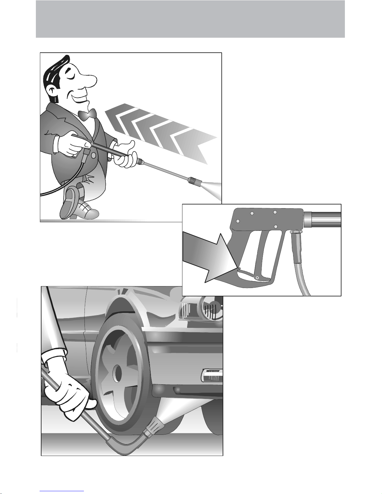
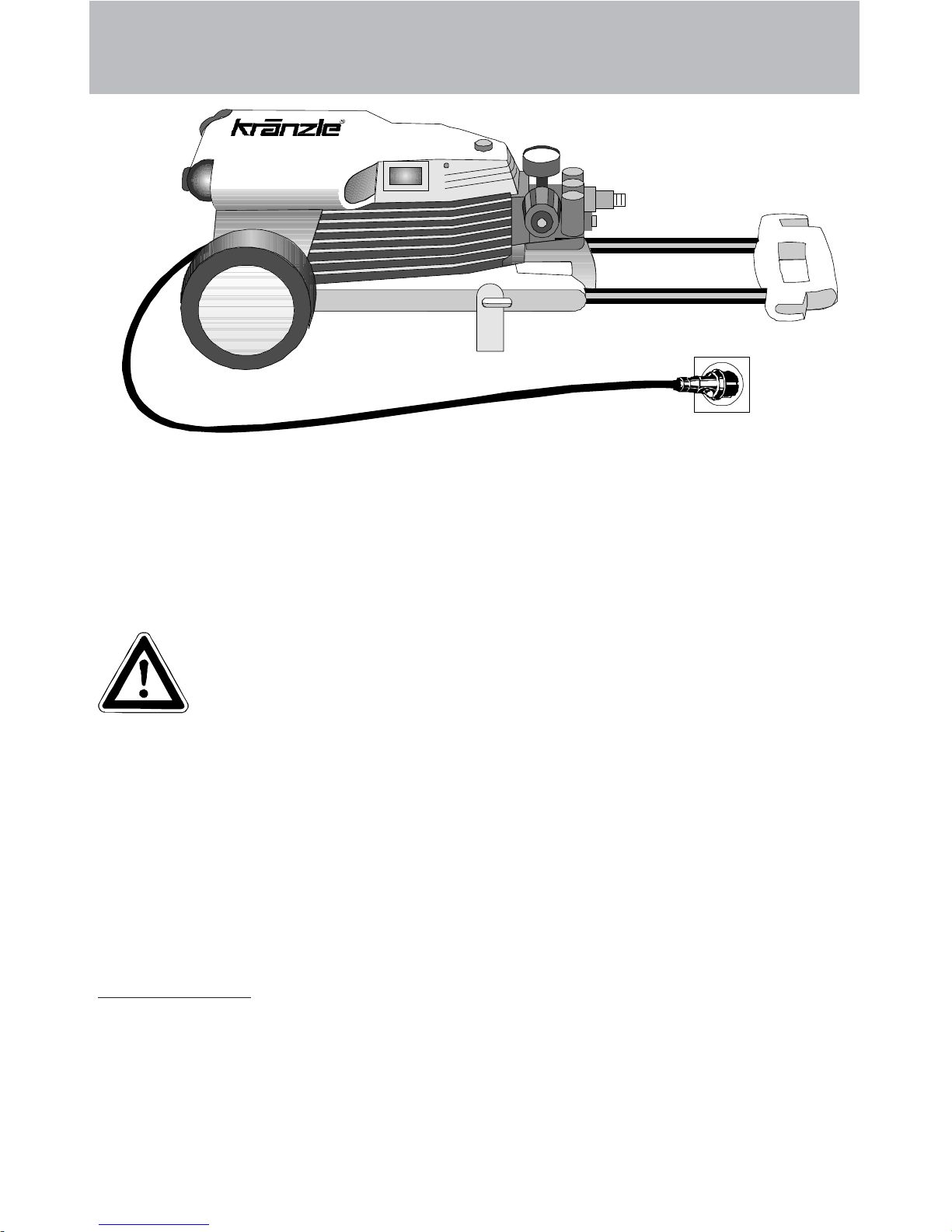
As to the recoil see notice on page 2!
Apply the safety catch on the
spray gun after each use, in
order to prevent unintentional spraying!
Always aim the
underbody lance. Note
when using an angled
underbody lance, like
for example lance No.
41075, that there is a
certain amount of
torque in the recoil.
(K115: 22 Nm
K125: 24 Nm
K135: 26 Nm
K155: 27 Nm)
Safety notes
9
Page 10
10
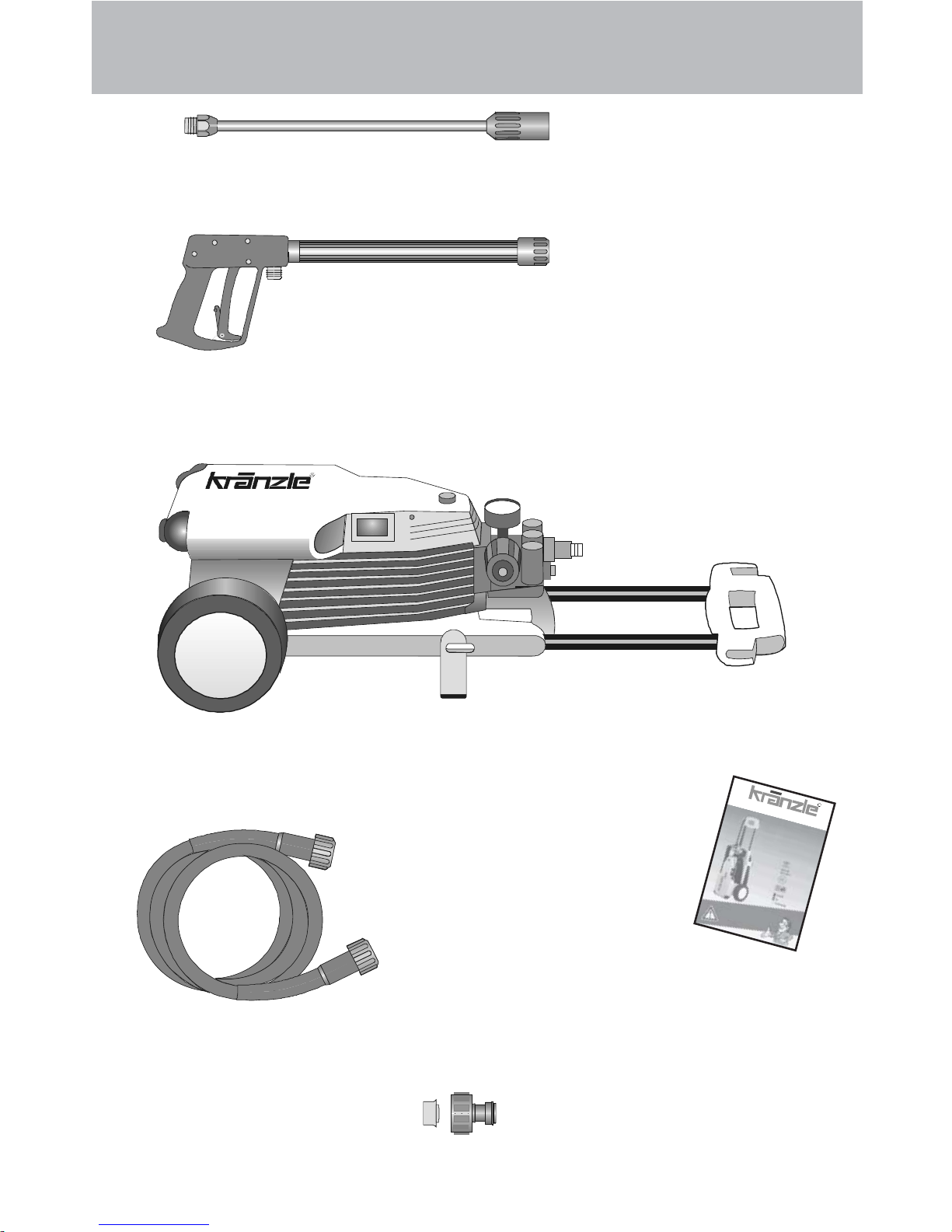
1. Spray lance with
regulator and high
pressure nozzle,
flat spray 25045
2. Spray gun with
insulated pistol grip
and screw connection
3. KRÄNZLE - High pressure cleaners 115, 125, 135 or 155
5. Operating
instructions
6. Water inlet components
This is what you’ve purchased:
4. High pressure hose 10 m with
steel reinforcement NW 6.
Filter already mounted
R
Page 11
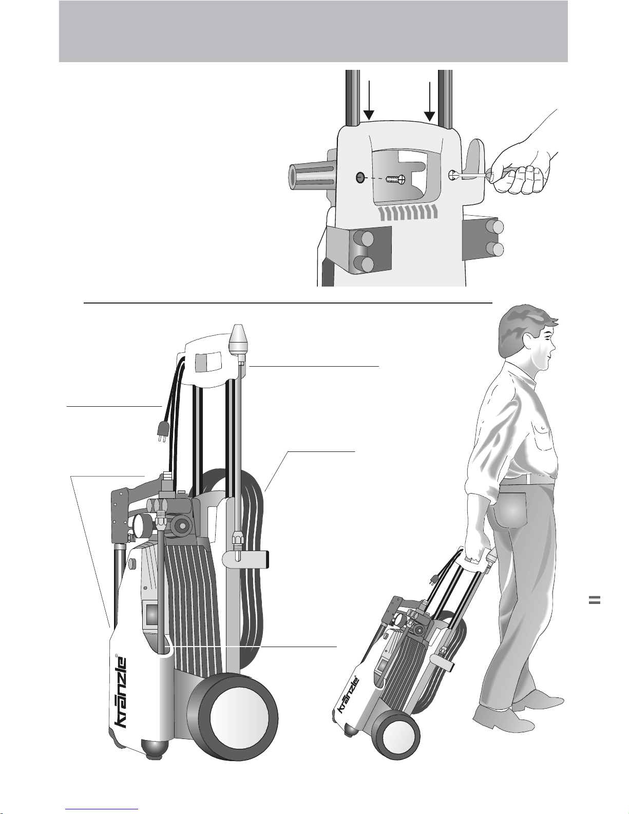
Put high Pressure cleaner into upright position.
Insert handle from
above and fasten with 2
screws from underneath.
Suspension for dirt
killer (special
accessory)
Cable
High pressure hose
Receptacle
for spray
gun
Receptacle
for lance
How to assemble and furnish your high pressure cleaner
11
Page 12
12
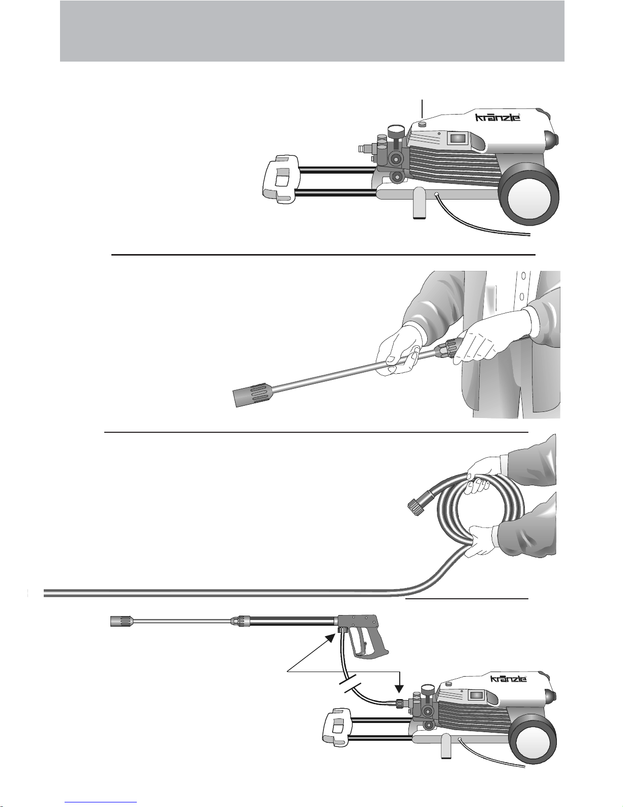
Preparation for use
1 . Put high pressure cleaner
into horizontal position!
THE HIGH PRESSURE
CLEANER IS ONLY TO
BE OPERATED IN
HORIZONTAL
POSITION !
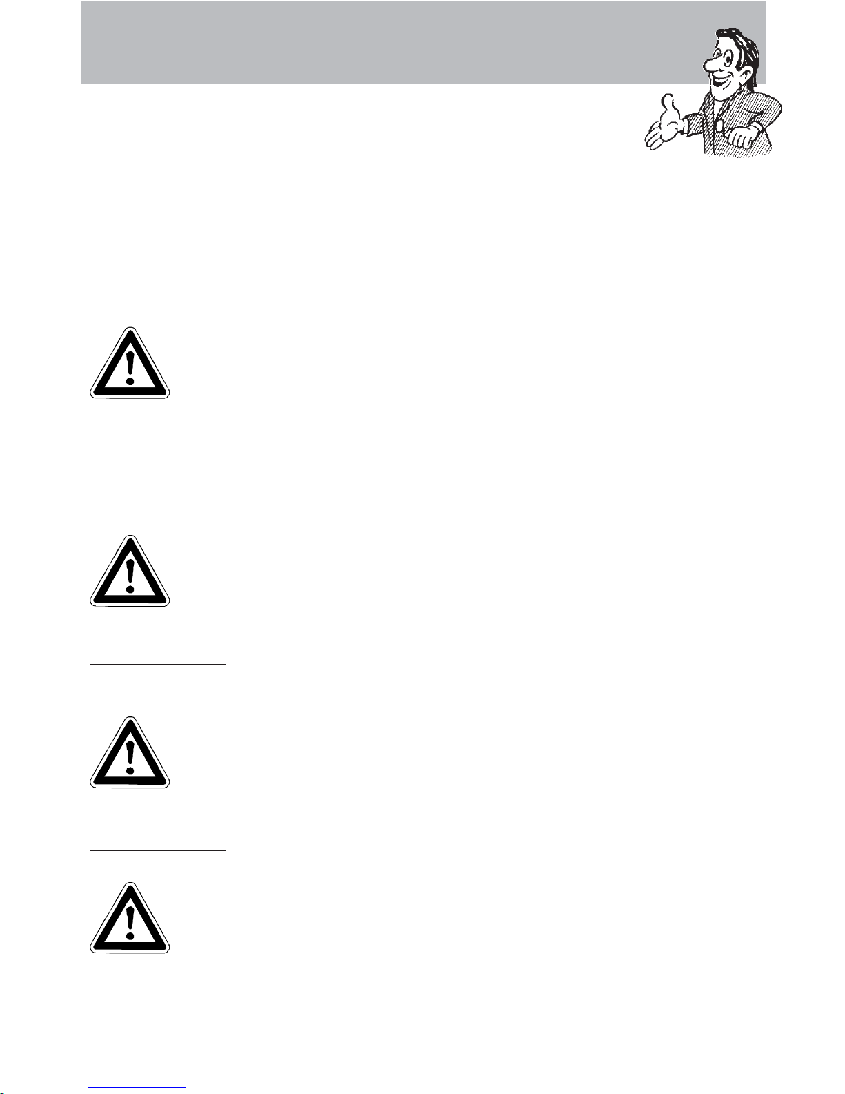
2. Connect the high pressure
lance to the spray gun.
3 . Unwind the high pressure hose
without leaving kinks or "nooses"
and connect it to the spray gun and
pump. When using extension hoses,
use max. 20 m high pressure hose,
or 2 x 10 m with hose connectors.
High pressure hose
connected from the
machine to the lance.
Do not replace the plug !
Page 13

4 . The machine can be connected to a
pressurised water line with cold or
60°C hot water
(see page 2).
Ensure that the water supply is
clean when sucking from external
sources. The hose cross section
must be at least 1/2” = 12.7 mm
(free passage). Filter 1
must always be clean.
Please make sure
that the filter 1 is clean before using your high pressure
cleaner.
CAUTION !
When running your high pressure cleaner with hot water of 60°
raised temperatures occur.
Do not touch the pump without safety gloves!
Water
5. Maximum induction height 2.5 m
see technical
data on page 2
Preparation for use
13
Page 14

14
4
5
A mixing ratio of 3-5% is
achieved when the Vario-Jet is
fully turned on. pH value neutral
7-9.
Turn on Vario-Jet to reach low
pressure !
This is accomplished by turning the
handwheel. The default setting is
maximum pressure.
Adjusting the pressure
Unwind HP-hose completely. Place
chemical filter no. 5 in the reservoir
with the cleansing agent. Turn on VarioJet No.4 to to enable the injector to
induct the cleansing agent. By turning
back the Vario-Jet nozzle, the supply of
chemical is automatically cut off. Allow the cleansing agent to
take effect and then remove with high pressure spray.
When using cleansing
agents:
Note that you must always
comply with the instructions
provided by the manufacturer of the cleansing agent
(e.g. instructions concerning
safety clothing) and the water protection regulations!
To shut down the pump:
1. Switch off the machine.
2. Cut off the water supply.
3. Open the spray gun briefly until the pressure is released.
4. Apply the safety catch on the spray gun.
5. Remove the water hose and spray gun.
6. Drain the pump: switch on the motor for approx. 20 seconds.
7. Pull the plug from the socket.
8. Winter: store the pump in rooms above 0°C.
9. Clean the water filter.
Preparation for use
Page 15

Never direct the
water jet at the
machine itself !
Never direct the
water jet at a
power socket !
Never allow
children to use the
high pressure cleaner !
This is prohibited !
15
Page 16

16
Never direct the
water jet at people
or animals !
Do not damage the
power cord or repair
it incorrectly !
Never pull the high
pressure hose if it
has formed kinks or
“nooses”!
Never pull the hose
over sharp edges !
This is prohibited !
Page 17

Additional KRÄNZLE-accessories for ...
Rotary scrubbing brush
Order No. 41050 1
Drain and pipe cleaning hose
8 m - Order No. 41051
15 m - Order No. 41058
Underbody lance, new
Order No. 41075 1
Sandblaster
Order No. 41068 1
Flat brush
Order No. 41073
Dirtkiller
Order No. 41072 5
Environmental, refuse disposal and
water protection regulations must be
observed when using the accessories!
17
Page 18

18
... for further combination possibilities
Car cleaning, glass, caravan, boat etc.
rotary washing brush with 40 cm extension and ST 30 nipple M 22 x 1,5
Underbody cleaning of cars, trailers and
equipment: lance 90 cm with high pressure
nozzle and ST 30 nipple M 22 x 1,5.
The lance must be aimed when
spraying.(see page 9)
Cleaning cars and all smooth surfaces :
brush with ST 30 nipple.
Rotary point sprayer for extreme soiling.
Dirtkiller with 40 cm extension and ST 30
nipple.
Cleaning pipes, channels and drains:
pipe cleaning hose with KN nozzle
and ST 30 nipple M 22 x 1,5
Blasting old paint, rust and facades: sandblasting injector with suction lance, 3 m
PVC hose and ST 30 nipple.
When sandblasting you must
wear protection clothes! Pay
attention to the instructions
of the manufacturer of the
abrasive!
Page 19

The pressure gauge shows a 10% higher pressure than the working pres
You only get a weak flow of water or no water at all!
Then straighten a
paper clip ...
and release the
injector with an
open-ended
spanner
Remove the injector
together with the
spring and return
valve.
and check that
it is clean.
Reconnect the hose,
and you are
ready to continue
your work!
and replace the
return valve.
The injector may be dirty and
you should
first
remove
the hose!
Now turn on the water
and you should get a
powerful stream of water
But if you only
get a weak flow
Clean the injector
thoroughly from both sides
19
Small repairs - Do it yourself!
Page 20

20
The nozzle is blocked!
No water but the gauge shows full pressure !
Rinse the hose
through first.
You should now have a
powerful stream of
water,
but if you
only get a few
drops from
the lance
remove the lance and clean
the nozzle.
Using the flat spray lance you
only have to clean the
front nozzle.
Straighten a paper
clip and clean the
nozzle.
Insert pointed object
into the hole and pull
the cap back!
Check visually whether the
nozzle is clean.
Now it works as well
as before.
Small repairs -
Page 21

Pressure gauge does not show full pressure.
Water comes out in spurts.
If you do not use the high-pressure cleaner for some time the valves
can stick
Nozzle dirty or sticky!
The high-pressure
hose vibrates.
Straighten a
paper clip...
When a valve is blocked,
the gauge
shows little
pressure or
no pressure
at all,
or the high
pressure
hose vibrates!
Open the valve
with a socket
wrench...
and remove the
valve screw, the
valve and the
o-ring.
Replace the rubber o-ring.
and remove the dirt
from the valve - the
valve inside must
be closed.
Retighten the valve
screw
...and repeat
on all 6 valves.
Now it works as
well as before!
- Do it yourself!
21
Page 22

22
Small repairs - Do it yourself!
Stopping leaks from hose or gun
After closing the gun the manometer shows full pressure !
The pressure regulator switches on and off contunuously!
If the
manometer
shows full
pressure,
Press the
trigger to
release the
pressure!!!
First
disconnect
the hose!
Then unscrew the
pump outlet with an
open-jew wrench.
Clean the return
element or replace
the O-Ring !
The pressure
regulator
switches on
and off from
pressure
loss!
Water can emerge at
these 3 points.
Check the seals and
replace the O-Ringe if necessary
or ave the gun checked by the dealer.
Replace the O-Ring
at the lance or at the
HP hose respectively!
Reconnect
the hose, gun
and lance!
Problem
solved already!
Pull out the
power plug!
Page 23

Trigger gun with lance
23
Ersatzteilliste Pistole mit Lanze
No Description Qty. Ord.-No
Midi-Gun 12.160
Lance compl. with regulator nozzle 042 12.700-MX20042
5 Rohranschlussteil R1/4“ 1 12.125
incl. Pos. 3, 4, 21
6 Schei be 5,3 DIN9021 1 50.152
7 Abzug-Hebel kpl. 1 12.144 1
12 Mutter M4 2 12.138
15 Rohr kunststoffumspritzt bds. R 1/4" AG 1 15.004 2
16 Überwurfmutter ST 30 M 22 x 1,5 IG 1 13.276 1
17 Außen-Sechskant- Nippel R 1/4 " IG 1 13. 277 1
18 O-Ring 9,3 x 2,4 1 13.273
28 Alumi nium Dichtring 6 13.27 5 1
30 ST 30-Nippel M 22 x 1,5 AG / M 12 x 1 1 13.363
31 Rohr 400 lang, bds. M12 x 1 1 41.527
32 Kunststoff-Hülse 1 13.202
33 Regeldüse ohne Hülse 1 43.439
34 Sprengring 1 43.441
35 O-Ring 6,0 x 3,0 1 14.121
36 HD-Düse MX20042 1 MX20042
36.1 HD-Düse M20030 1 M20030
37 Düsenhalter 1 26.004
A
Rep.-Kit 12.158
Pos: 3, 4, 5, 6, 8, 9, 10, 11, 12; 28
B Griff komplett 12.164
Page 24

24
Complete assembly
Page 25

25
KRÄNZLE 115 / 125 / 135 / 155
No Description Qty. Ord.-No
1 Motor WECHSELSTROM für K 115 1 43.448
1 Motor WECHSELSTROM für K 125 1 43.400
1 Motor WECHSELSTROM für K 135 1 43.302
1 Motor DREHSTROM für K 155 1 43.327
Motoren jeweils komplett mit Ölgehäuse
und Lüfterrad ohne Schalter
2 Gehäusehälfte rechts 1 43.402
3 Halterung Kondensator 1 43.403
4 Gehäusehälfte links K 115 1 43.404 1
4.1 Gehäusehälfte links K 125 1 43.404 2
4.2 Gehäusehälfte links K 135 1 43.404 3
4.3 Gehäusehälfte links K 155 1 43.404 4
5 Gummidämpfer 2 43.405
6 Unterschale 1 1 43.406
7 Unterschale 2 K 115 1 43.407 1
7.1 Unterschale 2 K 125 1 43.407 2
7.2 Unterschale 2 K 135 1 43.407 3
7.3 Unterschale 2 K 155 1 43.407 4
8 Handgriff Schale 1 1 43.408
9 Handgriff Schale 2 1 43.409
10 Schlauchhalter R (rechts) 1 43.410
11 Schlauchhalter L (links) 1 43.411
12 Rad 2 43.412
13 Radkappe 2 43.413
14 PICO-Pistole mit Verlängerung 1 41.053 1
15 Schmutzkiller 045 mit Lanze 1 41.072 5
16 Regeldüse mit HD-Düse 20042 und Lanze 1 12.700-MX20042
17 Rohr für Handgriff 1 43.414
No Description Qty. Ord.-No
18 Kunststoffschraube 3,5 x 20 5 43.415
19 O-Ring 9,3 x 2,4 2 13.273
20 HD-Schlauch NW 6 10 m 210 bar 1 43.416
21 Chemikaliensaugschlauch mit Filter 1 15.038
22 Kunststoffschraube 4,0 x 16 5 43.417
23 Kunststoffschraube 5,0 x 30 2 43.418
24 Gummidämpfer 4 43.419
25 Kunststoffschraube 4,0 x 60 2 43.420
26 Schraube M 6 x 12 4 43.421
27 Knickschutztülle 1 43.422
28 Kabel mit Stecker (Wechselstrom)
für Kränzle 115 / 125 / 135 1 41.092
28.1 Kabel mit Stecker (Drehstrom)
für Kränzle 155 1 41.092 1
29 Kunststoffschraube 6,0 x 30 2 43.423
30 Starlock-Kappe Durchmesser 12 2 43.424
31 Schraube M 5 x 10 8 43.021
32 Kunststoffschraube 2 43.425
33 Schaumstoffrohr für Kondensator 1 41.418
34 Kunststoffschraube 5,0 x 14 4 43.426
35 Haltebügel 2 43.427
36 Bodenblech mit Motorachse 1 43.428
37 Kuststoffscheibe 12,5 mm 2 43.429
38 Kunststoffschraube 3,5 x 8 8 43.430
39 Kabelklemme 2 43.431
40 Kunststoffschraube 5,0 x 80 2 43.432
41 Kunststoffschraube 5,0 x 120 1 43.309
42 Schalterblende 1 43.433
43 Kabelführung 2 43.061
44 Kabelauflage 1 43.062
Spare parts list KRÄNZLE 115 / 125 / 135 / 155
Complete assembly
Page 26

26
Valve housing 18 mm
Page 27

27
No Description Qty. Ord.-No
No Description Qty. Ord.-No
Spare parts list KRÄNZLE 115 / 125 / 135 / 155
Valve housing APG for plunger diameter 18 mm
KRÄNZLE 115 / 125 / 135 / 155
Rep.-kit valves for APG-pump 41.748 1
consisting of: 6x Pos. 4; 6x Pos. 5; 6x Pos. 6
Rep.-kit sleeves 18 mm 41.049 1
consisting of: 3x Pos. 27; 3x Pos. 28;
3x Pos. 28.1; 6x Pos. 29; 3x Pos. 30
Valve housing compl. 43.442
with integr. ULH
Guide piston compl. with handwheel 43.444
1 Ventilgehäuse 1 43.435
2 Ventilstopfen 6 41.714
3 Dichtstopfen M 10 x 1 1 43.043
4 Ventile (grün) für APG-Pumpe 6 41.715 1
5 O-Ring 16 x 2 7 13.150
5.1 O-Ring 13,94 x 2,62 1 42.167
6 O-Ring 15 x 2 6 41.716
7 Dichtstopfen R1/4" mit Bund 1 42.103
8 O-Ring 11 x 1,44 1 12.256
9 Edelstahlsitz 1 14.118
10 Sicherungsring 1 13.147
11 Edelstahlkugel 8,5 mm 1 13.148
12 Edelstahlfeder 1 14.119
13 Verschlussschraube 1 14.113
14 Steuerkolben 1 14.134
15 Parbaks 16 mm 1 13.159
16 Parbaks 8 mm 1 14.123
17 Spannstift 1 14.148
18 Kolbenführung spezial 1 42.105
19 Mutter M 8 x 1 2 14.144
20 Ventilfeder schwarz 1 14.125
21 Federdruckscheibe 1 14.126
22 Nadellager 1 14.146
23 Handrad 1 14.147
25 Elastic-Stop-Mutter 1 14.152
26 Manometer 0-250 bar 1 15.039
27 Druckring 3 41.018
28 Manschette 18 x 26 x 4/2 3 41.013
28.1 Gewebem anschette 18 x 26 x 4/2 3 41.013 1
29 Backring 18 x 26 6 41.014
30 O-Ring 28,3 x 1,78 3 40.026
31 Leckagering 18 mm 3 41.066
32 Zwischenring 18 mm 3 41.015 2
33 O-Ring 15 x 1,5 1 42.104
34 O-Ring 6 x 3 1 14.121
35 Rückschlagkörper 1 14.122
36 Rückschlagfeder 1 14.120
37 O-Ring 18 x 2 1 43.446
38 Ausgangsstück Injektor ST30 M22x1,5 1 43.447
39 Saugzapfen Schlauchanschluss 1 13.236
40 Edelstahlkugel 5,5 mm 1 13.238
41 Edelstahlfeder 1 13.239
42 Kupferring 1 42.104
43 Innensechskantschraube M 8 x 30 2 41.036 1
44 Innensechskantschraube M 8 x 55 2 41.017 1
46 Sauganschluss 1 41.016
47 Wasserfilter 1 41.046 2
48 Gummi Dichtring 1 41.047 1
49 Steckkupplung 1 41.047 2
50 O-Ring 1 41.047 3
51 Aluminium-Dichtrin
g
2 13.275
Page 28

28
Transmission unit 18 mm
Page 29

29
No Description Qty. Ord.-No
Spare parts list KRÄNZLE 115 / 125 / 135 / 155
Transmission unit for plunger diameter 18 mm
KRÄNZLE 115 / 125 / 135 / 155
1 Gehäuseplatte für 18 mm Plunger 1 41.020 2
2 Öldichtung 18 x 28 x 7 3 41.031
3 O-Ring Viton 88 x 2 1 41.021 1
4 Plungerfeder 3 41.033
5 Federdruckscheibe 18 mm 3 41.034
6 Plunger 18 mm 3 41.032 1
7 Sprengring 18 mm 3 4 1.035
8 Taumelscheibe 11,0°
bei Kränzle 115 Wechselstrom 1 46.542-11,0
8 Taumelscheibe 11,5°
bei Kränzle 125 Wechselstrom 1 46.542-11,5
8 Taumelscheibe 12,0°
bei Kränzle 135 Wechselstrom 1 46.542-12,0
8 Taumelscheibe 13,0°
bei Kränzle 155 Drehstrom 1 46.542-13,0
bitte Taumelwinkel jeweils mit angeben
10 Axial-Rollenlager 3-teilig 1 46.543
12 Innensechskantschraube M 8 x 30 4 41.036 1
13 Ölschauglas 1 42.018 1
14 O-Ring 14 x 2 3 43.445
15 Öleinfüll-Stutzen 1 43.438
16 Öl-Verschlussschraube Messin
g
1 43.437 1
Page 30

30
A. C. motor
Page 31

31
No Description Qty. Ord.-No
Spare parts list KRÄNZLE 115, 125, 135
A. C. motor
KRÄNZLE 115, 125, 135
1 Ölgehäuse für AP 1 43.314
2 Motorgehäuse mit Stator Wechselstrom
für Kränzle 115 / 125 1 43.400 9
2 Motorgehäuse mit Stator Wechselstrom
für Kr änzle 135 1 43.315
3 Rotor mit Motorwelle 1 43.316
4 Passfeder 6 x 6 x 20 1 41.483 1
5 Rillenkugellager 6205 - 2Z 1 43.317
6 Kegelrollenlager 31304 1 40.472
7 Toleranzhülse 1 43.330 1
8 Öldichtung 25 x 35 x 7 1 41.024
9 Lüfterrad BG 90 1 43.319
10 Lüfterhaube BG 90 1 43.320
11 Flachdichtung 1 43.030
12 Lüsterklemme 2-polig 1 43.031
13 Schaltergehäuse BG 90 1 43.321
14 Schalter mit 13,5 A Überstromauslöser 1 41.110 2
15 Klemmrahmen m it Schalterabdichtung 1 41.110 5
16 Kabelverschraubung PG 11 1 41.419
17 Kabelverschraubung PG 9 (3-teilig) 1 43.034
18 Kondensator 70 µF 1 43.322
19 Kabel mit Stecker 1 41.092
20 Blechschraube 3,5 x 9,5 2 41.088
21 Blechschraube 2,9 x 16 1 43.036
22 Schraube M 4 x 12 4 41.489
23 Innensechskantschraube M 6 x 30 4 43.037
24 Erdungsschraube kmpl. 1 43.038
25 Schraube M 4 x 12 2 41.489
26 Schelle für Lüfterrad mit Schrauben 1 43.454
Page 32

32
Three-phase current motor
Page 33

33
Spare parts list KRÄNZLE 155
Three-phase current motor
No Description Qty. Ord.-No
KRÄNZLE 155
1 Ölgehäuse für AP 1 43.314
2 Motorgehäuse mit Stator Drehstrom 1 43.324
3 Rotor mit Motorwelle 1 43.316
4 Passfeder 6 x 6 x 20 1 41.483 1
5 Rillenkugellager 6205 - 2Z 1 43.317
6 Kegelrollenlager 31304 1 40.472
7 Toleranzhülse 1 43.330 1
8 Öldichtung 25 x 35 x 7 1 41.024
9 Lüfterrad BG 90 1 43.319
10 Lüfterhaube BG 90 1 43.320
11 Flachdichtung 1 43.030
13 Schaltergehäuse BG 90 Drehstrom 1 43.452
14 Schalter (Amazonas) 8 A 1 43.450
15 Klemmrahmen mit Schalterabdichtung 1 43.453
17 Kabelverschraubung PG 13,5 1 40.539
19 Kabel mit Steck er Drehstrom 1 41.092 1
20 Blechschraube 3,5 x 9,5 2 41.088
22 Schraube M 4 x 12 4 41.489
23 Innensechskantschraube M 6 x 30 4 43.037
24 Erdungsschraube kpl. 1 43.038
25 Schraube M 4 x 12 2 41.489
26 Schelle für Lüfterrad mit Schrauben 1 43.454
Page 34

34
No Description Qty. Ord.-No
1 Sprühkörper 1 41.520
2 O-Ring 6,88 x 1,68 1 41.521
3 Düsensitz 1 41.522
4 Düse 045 1 41.523
5 Stabilisator 1 41.524
6 O-Ring 1 40.016 1
7 Sprühstopfen 1 41.526
8 Rohr 400 mm 2x M 12 x 1 1 41.527
9 ST 30-Nippel M 22 x 1,5 / M 12 x 1 ISK 1 13.363
Rep.-Kit Dirtkiller 045 41.097
consisting of: 1x 2; 3; 4; 5
Dirtkiller 045 with Lance 41.072 5
Spare parts list KRÄNZLE 115, 125, 135 155
Dirtkiller with lance (special accessory)
Dirtkiller
Page 35

35
Terminal strip
Weber-Unimat WT 22 - 551
13,5A excess current release
Motor-Stator
Switch Weber - Amazonas
8 A for K155
KRÄNZLE 155 400 Volt / 50 Hz
Motor with terminal box
KRÄNZLE 115, 125, 135 230 Volt / 50 Hz
Wiring diagram
70 μF
braun = brown
blau = blue
schw = black
rt = red
ge = yellow
gn = green
ws = white
Page 36

36
Inspections
The machine must be inspected according to the “Guidelines for Liquid Spray
Devices” at least once every 12 months by a qualified person, to ensure that
continued safe operation is guarateed. The results of the inspection are to be
recorded in writing. This may be done in any form.
Accident prevention
The machine is designed for accidents to be impossible if used correctly.
The operator is to be notified of the risk of injury from hot machine parts and the
high pressure water jet. The “Guidelines for Liquid Spray Devices” must be complied with. (see page 14 and 15)
Check the oil level at the oil sight glass prior to each use.
(Ensure horizontal position!)
Oil change:
The oil of your high pressure pump should be changed after approx. 40 hours of
operation, or no later than when it takes on a grey or whitish colour. To change the oil,
remove the two combination screws on the base-plate at the bottom, take off the
base-plate and pull out the oil drainage hose. Put the hose over a container and take
off the closure cap. Put the pump into horizontal position to drain off the oil. The oil
must be caught in a container and disposed of in a responsible, legal manner.
New oil: 0.3 l - Motor oil: W 15/40
General rules
Warranty
This warranty covers material and/or workmanship related defects only and does not
extend to ordinary wear.
Machine must be operated according to enclosed operating instructions which are part of
present warranty conditions.
A
ll products sold directly to private custome rs are warrantied for a period of 24 months,
whereas the warranty period for industrial purchases is limited to 12 months.
In case of any warranty claims, please have your HP cleaner together with accessories
and your purchase document ready and contact your nearest dealer or authorized service
point which can also be looked up in the internet at www.kraenzle.com .
Warranty is void in case of attempts to modify any of the safety devices or in the event of
exceeding temperature or rpm limits - this also applies to undervoltage, low water and/or
polluted water. Gauge, nozzle, valves, sealing gaskets, high pressure hose and spray
e
quip
ment are considered wear parts and do not fall under this warranty.
Page 37

I. Kränzle GmbH
Elpke 97 . 33605 Bielefeld
R
Hochdruckreiniger
High-pressure-cleaners
Nettoyeurs à Haute Pression
We hereby declare,
that the high-pressure models:
(techn. documentation available from):
comply with the following guidelines and
specifications and their amendments for
high-pressure cleaners:
Sound power level measured:
guaranteed:
Applied specifications and
standards:
EC declaration of conformity
(Managing Director)
Bielefeld, den 08.09.05
Kränzle 115 - 155
Manfred Bauer, Fa. Josef Kränzle
Rudolf-Diesel-Str . 20, 89257 Illertissen
Machine guideline 89/392/EEC
Low voltage guideline 73/23 EEC
Specification for electromagnetic
compatibility 89/336 EEC
Outdoor noise directive 2000/14/EC,
Art. 13, High-pressure water jet machines
Appendix 3, part B, chapter 27
K115-125: 87 dB (A); K135-155: 89 dB (A)
K115-125: 89 dB (A); K135-155: 91 dB (A)
EN 60 335-2-79 / A1:2004
EN 55 014-1 / A2:2002
EN 61 000-3-2 / A14:2000
EN 61 000-3-3 / A1:2001
Page 38

38
NotesNotes
NotesNotes
Notes
Page 39

39
NotesNotes
NotesNotes
Notes
Page 40

Best.-Nr.: 30.205 1
Reprint only allowed with the authorization of
As of date of 10. 12. 2008
R
 Loading...