

Page 1
High pressure cleaner
Reproduction only by permission of .
Date: 18. 06. 2004
Operating instructions
Read and confirm before use
110-115 V / 60 Hz 95 bar
R
Page 2
2
We would like to congratulate you on your new high pressure cleaner and to
thank you for the purchase.
To easy your introduction to the use of the cleaner, we have provided the
following pages of explanations, tips and hints.
The equipement will assist you professionally in all cleaning tasks, e.q.:
Dear Customer
Permissible tolenance for figures 5 % in accordance with
VDMA uniform sheet 24411
I. Kränzle GmbH
Elpke 97 . 33605 Bielefeld
DescriptionDescription
DescriptionDescription
Description
Hochdruckreiniger
High-pressure-cleaners
Nettoyeurs À Haute Pression
- facades
- flagstones
- terraces
- vehicles of all types
- sheds
- channels
Technical
specifications
operating pressure
permissible overpressure
water output
hot water input
electrical ratings
connected input:
wattage output:
fuse protection
weight
dimensions
sound level accord. to
DIN 45 635
with dirtkiller
recoil at lance
torque
Kränzle
junior 120
95 bar
110 bar
6.8 l/min at 1700 rpm
max. 60 °C
110-115 V ; 60 Hz ; 13,5 A
1,5 kW
1,2 kW
16 A (slow fuse)
17,5 kg packing excluded
20 kg packing included
lenght 550 mm
width 230 mm
height 380 mm
87 dB
88 dB
approx. 19 Nm
20 Nm (assumed length at lance: 0,9 m)
- barrels and
containers
- machines etc.
(Managing Director)
Herewith we declare
that
comply with the following
provisions applying to it
Applied
harmonized standards
in particular
EC declaration of conformity
Bielefeld, den 18.06.04
Kränzle junior 120
Maschinenrichtlinie 89/392/EWG
Niederspannungsrichtlinie 73/23 EWG
EMV-Richtlinie 89/336 EWG
Lärmrichtlinie 2000/14/EG
EN 60 335-2-79 / A1:2001
EN 55 014-1 / A2:2002
EN 55 014-2 / A1:2001
EN 61 000-3-2 / A14:2000
EN 61 000-3-3 / A1:2001
Page 3
26 3
Description
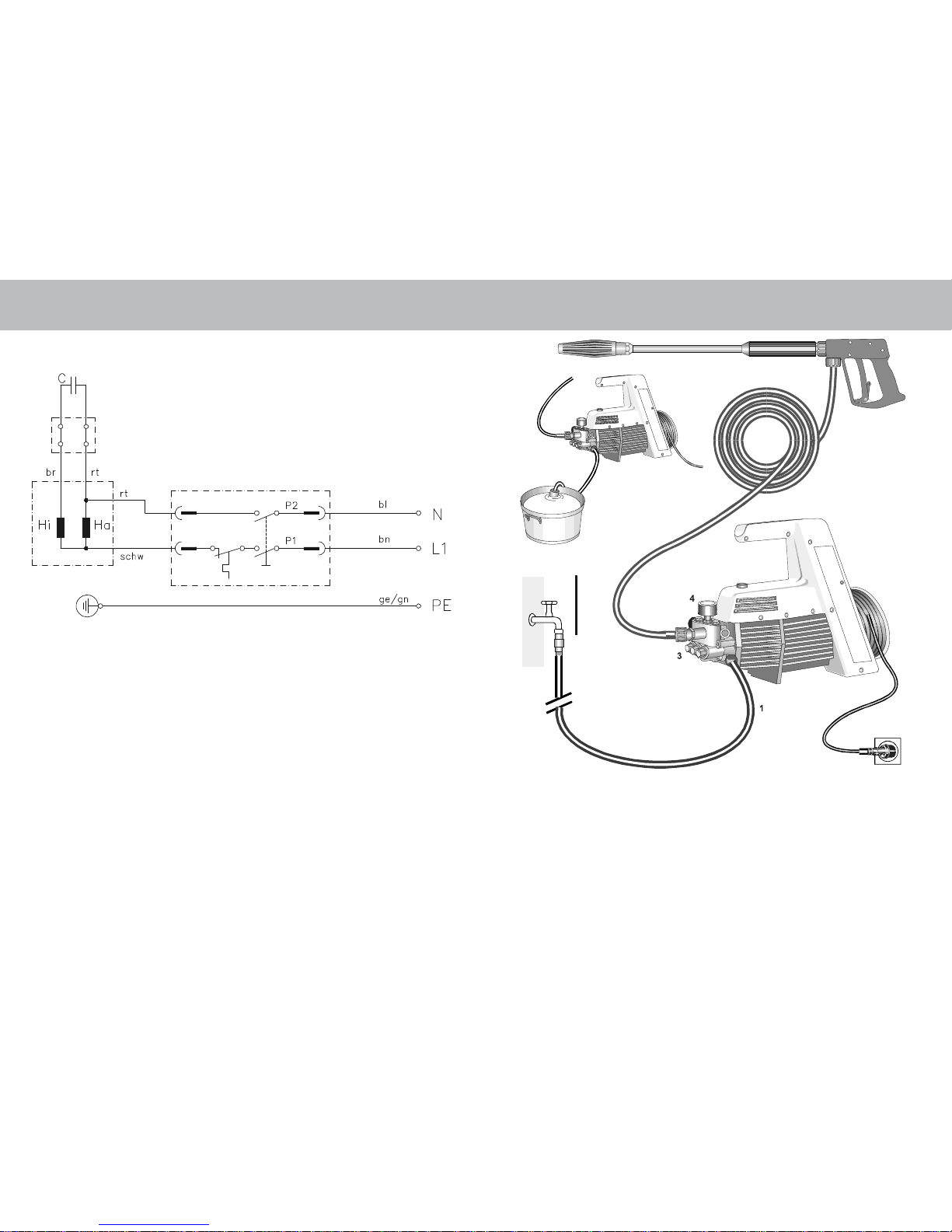
Construction
The Kränzle junior 120 high pressure cleaner is a portable machine.
The design can be seen from the diagram.
Wiring diagram
Water
8
2
5
6
7
110-115 V
Pipe air-release valve
with reflux valve
Item
1. Water inlet connection with a filter
2. Suction hose with filter
(special accessory)
3. High pressure pump
4. Pressure gauge
5. High pressure hose
6. Spray gun assembly
7. Interchangeable lance with Vario-Jet nozzle
8. Pipe air-release valve with reflux valve
Special accessory (Order no. 41.016 4)
Terminal strip
Switch with
16 A excess current release
Page 4
4 25
Description
Water and Cleaning System
Water can be connected at mains pressure to the high pressure pump or it can
be sucked dirctly from a storage tank. The water is then forced under pressure
by the high pressure pump to the lance.
The high pressure jet is formed by the nozzle at the end of the lance.
Environmental, refuse disposal and water protection
regulations must be observed !
Unloader valve - safety valve
The unloder valve - safety valve protects the machine from a build-up of
excess-pressure, and is designed not to permit an excess pressure to be
selected for operation. The limit nut of the unloader valve is sealed with a spray
coating.
Replacements, repairs, new adjustments and sealing
should only be performed by qualified persons !
Lance with trigger gun
The machine can be operated when the safety trigger is squeezed.
When the lever is squeezed, the spry gun opens. The liquid is then pumped to
the nozzle. The spray pressure increases and quickly reaches the selected
operating pressure.
When the trigger is released, the trigger gun closes and any further spraying of
liquid from the lance is stopped.
The increase in pressure when the trigger gun is closed causes the unloader
valve - safety valve closes and the pump ressumes pressure spraying from the
lance.
The trigger gun is a safety device. Repairs should only be performed by
qualified persons. Should replacement parts be required, use only
components authorized by the manufacturer.
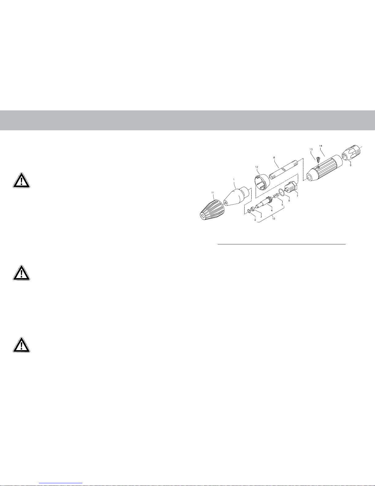
Dirtkiller with lance (special sccessory)Dirtkiller with lance (special sccessory)
Dirtkiller with lance (special sccessory)Dirtkiller with lance (special sccessory)
Dirtkiller with lance (special sccessory)
No. Description Qty. Order No.
1 Sprühkörper 1 41.520
2 O-Ring 6,88 x 1,68 1 41.521
3 Düsensitz 1 41.522
4 Düse 03 1 41.523 4
5 Stabilisator 1 41.524
6 O-Ring 1 40.016 1
7 Sprühstopfen 1 41.526
8 Rohr 400 mm 2x M 12 x 1 1 41.527
9 ST 30-Nippel M 22 x 1,5 / M 12 x 1 ISK 1 13.363
11 Kappe vorn für Schmutzkiller 1 41.528 1
12 Kappe hinten für Schmutzkiller 03 1 41.540 4
13 Schraube 3,5 x 9,5 1 41.088
14 Isoliergriff 150 mm 1 12.399
10 Rep.-Satz Schmutzkiller 03 41.096 1
bestehend aus je 1x
2; 3; 4; 5
Schmutzkiller kpl. mit Lanze und
Isolierhandgriff 43.094
Page 5
24 5
Description
Motor protection switch
The motor is protected from overload by a motor protection switch, which
automatically cuts out the motor in the event of overload.
However, should the switch trip frequently, the cause of the malfunction should
be located and rectified (see page 6).
Replacements and inspection work should only be performed ba
qualified persons when the machine is disconnected from the
power supply, i.e. pull the plug from the electrical socket before
such work is carried out.
Setting up
Location
Neither set up and operate the machine in rooms where there is a risk
of fire or explosion nor put it into puddles.
Do not use the machine under water.
CAUTION !
Never use liquid containing solvents such as paint thinners, patrol, oil
or similar liquid matter.
Pay attention to the instructions of the manufacturer of the
cleaning agents. The seals in the machine are not resistant to
solvents. The spray of solvents is inflammable, explosive and
poisonous.
CAUTION !
When running your high pressure cleaner with hot water of 60 °C raised
temperatures occur.
Do not touch the machine without safety gloves.
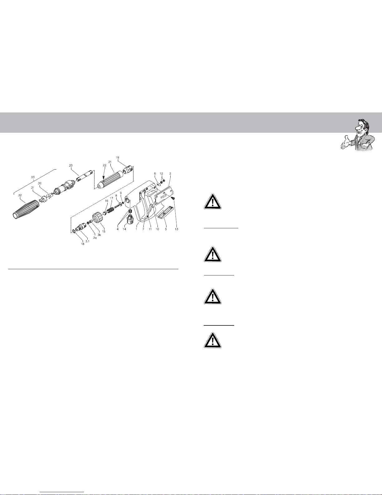
Spray gun with lance
No. Description Qty. Order No.
1 Handgriff mit Ventilkörper 1 12.165
2 Abdeckung seitlich 1 12.166
3.1 Rohranschlußteil 1 12.125 1
3a Messinghülse mit Teflonsitz 1 12.127
4 Aluminium Dichtring 2 13.275
5 Abdeckung unten 1 12.167
6 Druckplatte 1 12.168
7 Abzug-Hebel 1 12.169
8 Messingscheibe 1 12.135
9 O-Ring 3,3 x 2,4 1 12.136
10 Sicherungshebel 1 12.170
11 Stift 3 x 17 1 12.171
12 Kontermutter M 4 2 12.138
13 Schraube 3,9 x 9,5 4 12.172
14 ST 30-Nippel 1 13.365
M 22 x 1,5 / R 1/4" AG
15 Überwurfmutter ST 30 1 13.276 2
M 22 x 1,5 IG
16 Kolbenstange mit Kolben 1 12.143
17 Druckfeder leichte Ausführung 1 12.145 1
18 O-Ring 9,3 x 2,4 1 13.273
No. Description Qty. Order No.
Rep.-Satz PICO 12.158 1
bestehend aus je 1x
3.1; 3a+b; 8; 9; 12; 16; 17; 18
19 ST 30 - Nippel
M 22 x 1,5 / M 12 x 1 ISK 1 13.363
20 Rohr 400 mm 2x M 12 x 1 1 41.527
21 Isoliergriff 150 mm 1 12.399
22 Schraube 3,5 x 9,5 1 41.088
30 Klemmstück 1 41.155 2
31 Halterung für Klemmstück 1 41.155 4
32 Kunststoffhülle 1 41.155 1
33 Vario-Jet Düse 03 1 41.155 9
Vario-Jet 03 kpl. mit Lanze
und Isolierhandgriff 43.093
PICO-Pistole kpl. 43.092
Page 6

6 23
Valve housingDescription
Electrical connection
The machine is suplied with an electrical power cord with plug.
The mains plug must be fitted to a standard grounded socket with a
30 mA residual current operated device. The socket must be protected
with a 16 A slow fuse on the mains inside.
KRÄNZLE junior 120 - 110-115 Volt 60 Hz
When using an extension cable, this must have an earthed lead
which is properly connected to the socket. The conductors in the
extension cable must have a minimum cross section of 1,5 mm
2
.
Plug connections must be of a spray proof design, and may not be
located an a wet floor.
(With extension cables of more than 10 m the conductor must have
cross section of at least 2,5 mm
2
.)
CAUTION !
The use of extention cables which are too long may lead to malfunctions and
start-up difficulty.
When using a cable drum, always keep the cable wound as far as possible.
No. Description Qty. Order No.
1 Ventilgehäuse 1 43.065
2 Ventilstopfen mit integr. Ventil 5 43.066
3 Ventilstopfen mit integr. Ventil 1 43.067
R1/8" IG
4 Dichtstopfen M 8 x 1 1 13.158
5 O-Ring 10 x 2 6 43.068
6 Dichtstopfen M 10 x 1 1 43.043
7 O-Ring 1 43.099
8 Kugel 8,5 1 13.148
9 Edelstahlfeder 1 43.069
10 Stopfen M 14 x 1 1 40.595
11 O-Ring 8,5 x 2 1 43.070
12 Steuerkolben 1 43.071
13 Parbaks für Spindel 6 mm 1 14.123 2
14 Kolbenführung 1 43.072
15 Federdruckmutter M 6 1 43.073
16 Feder für Unloader 1 43.074
17 Druckring für 12 mm 3 43.091
17.1 Manschette 12 x 20 x 5,3/2,8 3 43.075
18 Backring 12 x 20 x 1,9 3 43.076
19 O-Ring Viton 5,23 x 2,62 1 43.056
No. Description Qty. Order No.
20 Rückschlagkörper 1 43.009
21 Rückschlagfeder 1 43.057
22 Ausgangsstück 1 43.077
23 Innensechskantschr. M 8 x 35 2 44 144
24 Innensechskantschr. M 8 x 25 2 40.053
25 Sauganschluß 1 41.016
26 Manometer 1 43.078
27 O-Ring 12 x 1,5 2 43.058
28 O-Ring 12 x 2 6 15.005 1
29 Mutter M 6 mit SW 8 2 43.010
Reparatur-Satz Ventile 43.098
Bestehend aus 5x Pos.2; 1x Pos.3
6x Pos.5; 6x Pos.28
Reparatur-Satz Manschetten 43.096
Bestehend aus 3x Pos.17;
3x Pos.17.1; 3x Pos. 18
Steuerkolben kmpl. 43.097
Bestehend aus 1x Pos.11; 1x Pos.12;
1x Pos.13; 1x Pos. 14; 1x Pos.15;
1x Pos. 16;1x Pos.27; 1x Pos.29
Page 7

22 7
DescriptionTransmission unit
No. Description Qty. Order No.
1 Gehäuseplatte 1 43.080
2 Öldichtung 12 x 20 x 6/5 3 43.081
3 O-Ring 83 x 2 1 43.039
4 Plungerfeder 3 43.040
5 Federdruckscheibe 3 43.082 1
6 Plunger 12 mm 1 43.083
7 Distanzbüchse 3 43.084
8 Taumelscheibe 12,5° 1 41.028-12,5
10 Axial-Rillenkugellager 3-teilig 1 43.486
12 Innensechskantschraube M 8 x 25 4 40.053
13 Ölschauglas 1 42.018 1
14 O-Ring 14 x 2 3 43.445
15 Öleinfüll-Stutzen 1 43.011
16 Ölverschlußschraube rot 1 43.437
17 O-Ring 21 x 1,5 3 43.085
18 Sprengring 12 mm 3 43.095
Brief operating instrucions
are fittet to the machine (numbers 1 - 6)
1. Connect the hogh pressure hose with spray gun
and machine.
2. Connect the suitable water supply.
3. Flush the air from the pump (open and close the spray gun
several times).
4. Make the electrical connection ( 110-115 Volt AC).
5. Switch on the machine while the spray gun is open and
commence cleaning.
6. After completing the work, completely empty the pump. (switch
the motor on for approx. 20 sec. without the suction and
pressure hoses).
- Only use clean water ! Protect from frost !
CAUTION !
Please pay attention to the regulations of your waterworks company.
In accordance with DIN 1988, the machine may not be directly connected to
the public drinking water supply lines.
A brief connection however is permissible according to DVGW (German
Associatin for Gas and Water Affairs) if a tube ventilator with reflux valve
(Kränzle Order-No. 41.016 4) is built into the water supply.
Also indirect connection to the public drinking water supply lines is
permissible by way of free emission in accordance with DIN 1988, part 4;
e.g. by using a reservoir with a float valve.
Direct connection to a non-drinking water supply line is permissible.
High pressure hose and spray device
The high pressure hose and spraying device suplied with the machine are
made of high grade material, they are also optimized for the machine and
marked as required by appropriate regulations.
If replacement parts are required, only such parts that are
authorized by the manufacturer and which bear the markings
required by appropriate regulations may be used. The high
pressure hose and spray device must be connected in a pressuretight manner. The high pressure hose may not be driven over,
pulled excessively, or twisted. The hose may under no
cicumstances be pulled over sharp edges, since otherwise the
guarantee is automatically void.
Page 8

The recoil is less
than 20 Nm.
Always aim the
underbody lance.
Note, when using an
angled underbody lance,
like for example lance
No. 41.075, that there is a
certain amount of torque
(twisting motion) in the
recoil. (See also notice
on page 2).
MotorSavety notes
8 21
Apply the safety catch
on the spray gun
after each use,
in order to prevent
unintentional spraying.
No. Description Qty. Order No.
1 Ölgehäuse 1 43.006
2 Motorgehäuse mit Stator 1 43.103
3 Motorwelle mit Rotor 1 43.104
4 Paßfeder 6 x 6 x 20 1 41.483 1
5 Motor-Lager B-Seite Z-Lager 1 43.025
6 Motor-Lager A-Seite Schulterl. 1 43.026
7 Federausgleichsscheibe 1 43.027
8 Öldichtung 25 x 35 x 7 1 41.024
9 Lüfterrad 1 43.028
10 Lüfterhaube 1 43.029
11 Flachdichtung 1 43.030
12 Lüsterklemme 1 43.031
13 Schaltergehäuse 1 43.032
14 Schalter mit 1 43.102
16 A-Überstromauslöser
15 Klemmrahmen mit 1 41.110 5
Schalterabdichtung
No. Description Qty. Order No.
16 Kabelverschraubung PG 11 1 41.419
17 Kabelverschraubung PG 9 1 43.034
18 Kondensator 80 μF 1 43.505
19 Kabel mit Stecker 1 43.512
20 Blechschraube 3,5 x 9,5 2 41.088
21 Blechschraube 2,9 x 16 1 43.036
22 Schraube M 4 x 12 4 41.489
23 Innensechskantschr. M 6 x 30 4 43.037
24 Erdungsschraube kpl. 1 43.038
Page 9

This is what you've purchased:Complete Assembly
Spray gun with screw connection
High pressure hose, 8 m
Water inlet components
(filter already installed)
No. Description Qty. Order No.
1 Motor komplett mit Ölgehäuse und 1 43.001 3
Lüfterrad ohne Schalter
2 Gehäusehälfte rechts 1 43.086
3 Gehäusehälfte links 1 43.087
4 Gummidämpfer klein 4 43.015
5 Gummidämpfer groß 1 43.016
6 Lüfterblende 1 43.017
7 Motorauflage 1 43.012
8 Kunststoffschraube 4,8 x 16 2 43.018
9 Kunststoffschraube 4,8 x 50 5 41.411
10 Kunststoffschraube 5,0 x 120 1 43 309
11 Senkkopfschraube 3 x 45 1 43 020
12 Blechschraube 4,8 x 13 8 44 112
13 Schaumstoffrohr 1 41.418
14 Pico-Pistole leichte Ausführung 1 43.092
ohne Verlängerung
15 Vario-Jet 03 mit Isoliergriff 150 mm 1 43.093
16* Schmutzkiller 03 mit Isoliergriff 150 mm 1 43.094
* Sonderzubehör
17 Schlauch 150 bar 1 41.054 1
18 O-Ring 9,3 x 2,4 2 13.273
20 9
Operating instructions
Spray lance with Vario-Jet high pressure nozzle,
adjustable from flat spray to point spray
KRÄNZLE - high pressure
cleaner junior 120
Page 10

10 19
- do it yourself !Preparation for use
Connect the high pressure
lance to the spray gun.
Unwind the high pressure hose without
leaving kinks or "nooses" and connect
it to the spray gun and pump.
When using extention hoses, use max.
20 m high pressure hose, or 2x 8 m
with hose connectors.
The high pressure hose
connected from the machine
to the lance.
The nozzle is blocked !
No water but the gauge shows full pressure.
Rinse the hose
through first.
Using the flat spray lance
you only have to clean the
front nozzle.
Check visually, whether
the nozzle is clean !
Now it works
as well
as before.
You should now have
a powerful stream
of water,
But if you
only get a few
drops of water
from lance,
remove the lance and clean
the nozzle.
Straighten a paper clip
and clean the nozzle !
Clean the nozzle !
Page 11

18 11
Preparation for useSmall repairs -
Tehe machine can be connected to a
pressurised water line with cold or
60 °C hot water. Ensure that the
water supply is clean when sucking
from external sources. The hose
cross section must be at least
1/2" = 12.7 mm (free passage).
Filter 1 must always be clean.
Water
CAUTION !
When running your high pressure cleaner with hot water of 60 °C raised
temperatures occur.
Do not touch the machine without safety gloves.
Please make
sure that the filter is
clean before using your
high pressure cleaner.
Maximum suction hight 1 m.
A Valve dirty or sticky !
Pressure gauge does not show full pressure.
Water comes out in spurts.
If you do not use the high pressure cleaner for some time the valves can stick.
Straighten a
paper clip...
the gauge
shows little
pressure or
no
pressure
at all.
or the high
pressure
hose vibrates!
Open the
valves with a
socket wrench...
remove the
valve screw, the
valve and the
O-ring.
Rplace the rubber
O-ring.
and remove the dirt
from the valve - the
inside must be
closed.
Retighten the
valve screw,
and repeat an all
6 valves.
Now it works as
well as before.
The high-pressure hose
vibrates.
When a valve is blocked.
Page 12

12 17
Preparation for use
When using cleansing agents:
For this machine a screwed-in injector no. 1 for inducting cleansing-agents is
available as special accessories.
(Screwed-in injector order no. 13.376 2).
Place chemical filter no. 2 in the reservoir with the cleansing agent. Push VarioJet no. 3 to front position to enable th injector to induct the cleansing agent. By
sliding back the Vario-Jet nozzle, the supply of chemical is automatically cut off.
Allow the cleansing agent to take effect and then remove with high pressure
spray.
Car cleaning, glass, caravan, boat etc.: rotary
washing brush with 40 cm extension and
ST 30 nipple M 22
Underbody cleaning of cars, trailers and
equipment: lance 90 cm with high pressure
nozzle and ST 30 nipple. The lance must be
aimed when spraying.
Cleaning cars and all smooth surfaces: brush
with ST 30 nipple M 22.
Rotary point sprayer for extreme soiling: dirt
killer with 40 cm extension and
ST 30 nipple M 22.
To shut down the pump:
1. Switch off the machine.
2. Cut off the water supply.
3. Open the spray gun briefly until the pressure is released.
4. Apply the safety catch on the spray gun.
5. Remove the water hose and high pressure hose.
6. Drain the pump: switch on the motor for approxx 20 sec. .
7. Pull the plug from the socket.
8. Winter: store the pump in rooms above 0 °C.
9. Clean the water filter.
1
3
2
Note that you must always
comply with the instuctions
provided by the manufacturer of the cleansing
agent (e.g. instructions
concerning safety clothing)
and the water protection
regulations.
for further combination possibilities
Page 13

16 13
This is prohibited !Additional KRÄNZLE-accessories
Never akkow children
to use the
high pressure cleaner !
Never direct
the water jet at the
machine itself !
Rotary scrubbing brush
Order No. 41.050 1
Underbody lance
Order No. 41.075
Flat brush
Order No. 41.073
Dirtkiller
Order No. 43.094
Environmental, refuse disposal water
protection regulations must be observed
when using the accessories.
Never direct the
water jet at a
power socket !
Page 14

14 15
General rulesThis is prohibited !
Never direct the
water jet at
people or animals !
Do not damage
the power cord
or repair it
incorrectly !
Inspections:
The machine must be inspected according to the "Guidelines for Liquid
Spray Devices" at least once every 12 months by a qualified person, to
ensure that continued safe operation is guaranteed. The results of the
inspection are to be recorded in writing. This may be done in any form.
Accident prevention
The machine is designed for accidents to be impossible if used correctly.
The operator is to be notified of the risk of injury from hot machine parts and
the high pressure water jet. The "Guidelines for Liquid Spray Devices" must
be complied with. (See page 13 + 14)
Please pay attentions to the regulations of your waterworks company.
(Reflux valve with tube ventilation according to DIN 1988)
Check the oil level at the oil sight glass prior to each use.
(Ensure horizontal position !)
Oil change:
No oil change is required during the working life of the machine. We would
suggest though to change the oil after having used the high pressure cleaner for a longer period of time to ensure its longevity. Should it be necessary
to change the oil the oil sight glass is to be opened over a reservoir and the
machine to be emptied. The oil is to be caught in the reservoir and disposed
of in the approved manner.
New oil: 0,25 l - Motor oil W 15/40
Never pull the high
pressure hose if it has
formed kinks or "nooses" !
Never pull the hose
over sharp edges !
Warranty
This warranty covers material and/or workmanship related defects only and does
not extend to ordinary wear.
Machine must be operated according to enclosed operating instructions which are
part of present warranty conditions.
All products sold directly to private customers are warrantied for a period of 24
months, whereas the warranty period for industrial purchases is limited to 12
months.
In case of any warranty claims, please have your HP cleaner together with
accessories and your purchase document ready and contact your nearest dealer or
authorized service point which can also be looked up in the internet at
www.kraenzle.com .
Warranty is void in case of attempts to modify any of the safety devices or in the
event of exceeding temperature or rpm limits - this also applies to undervoltage, low
water and/or polluted water. Gauge, nozzle, valves, sealing gaskets, high pressure
hose and spray equipment are considered wear parts and do not fall under this
warranty.
 Loading...