

Page 1
www.kraenzle.com
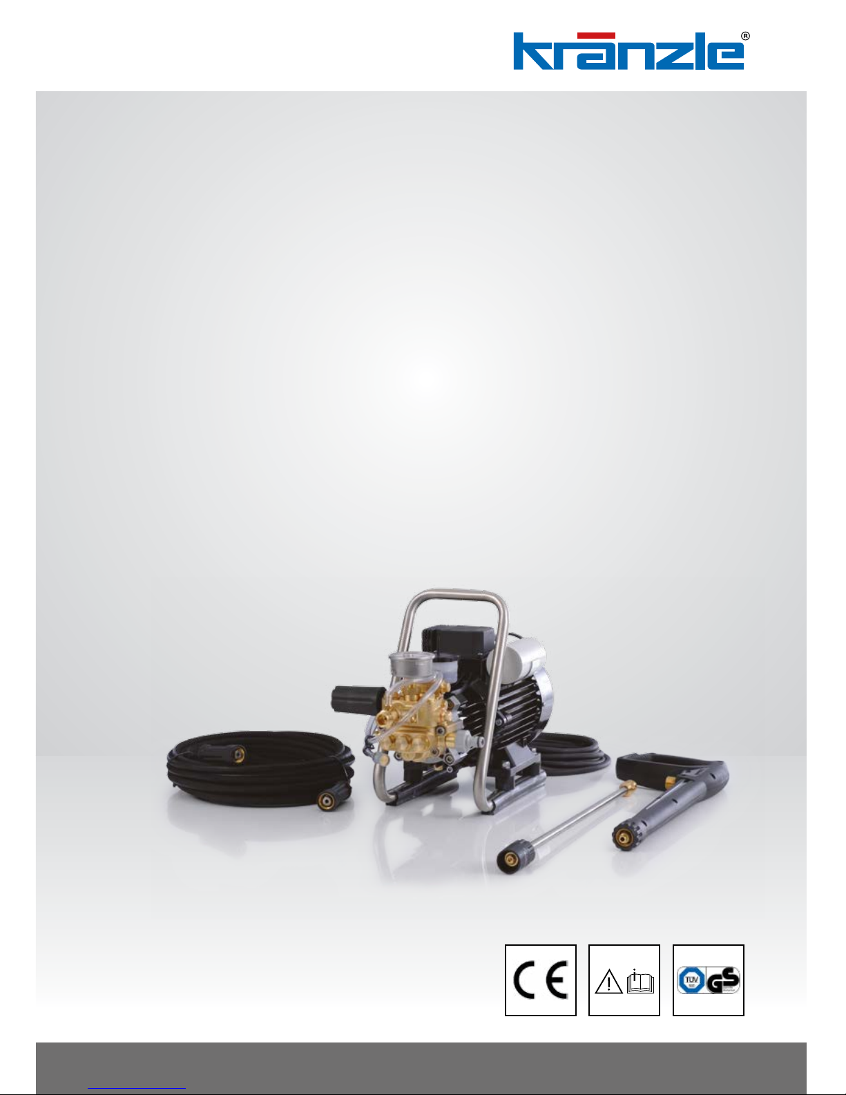
HD 9/80
HD 12/130
Original operating manual
High-pressure cleaners
Read and conform safety instructions before use!
Keep instructions in a safe place for later use and
pass them on to any future user.
- GB -
Page 2
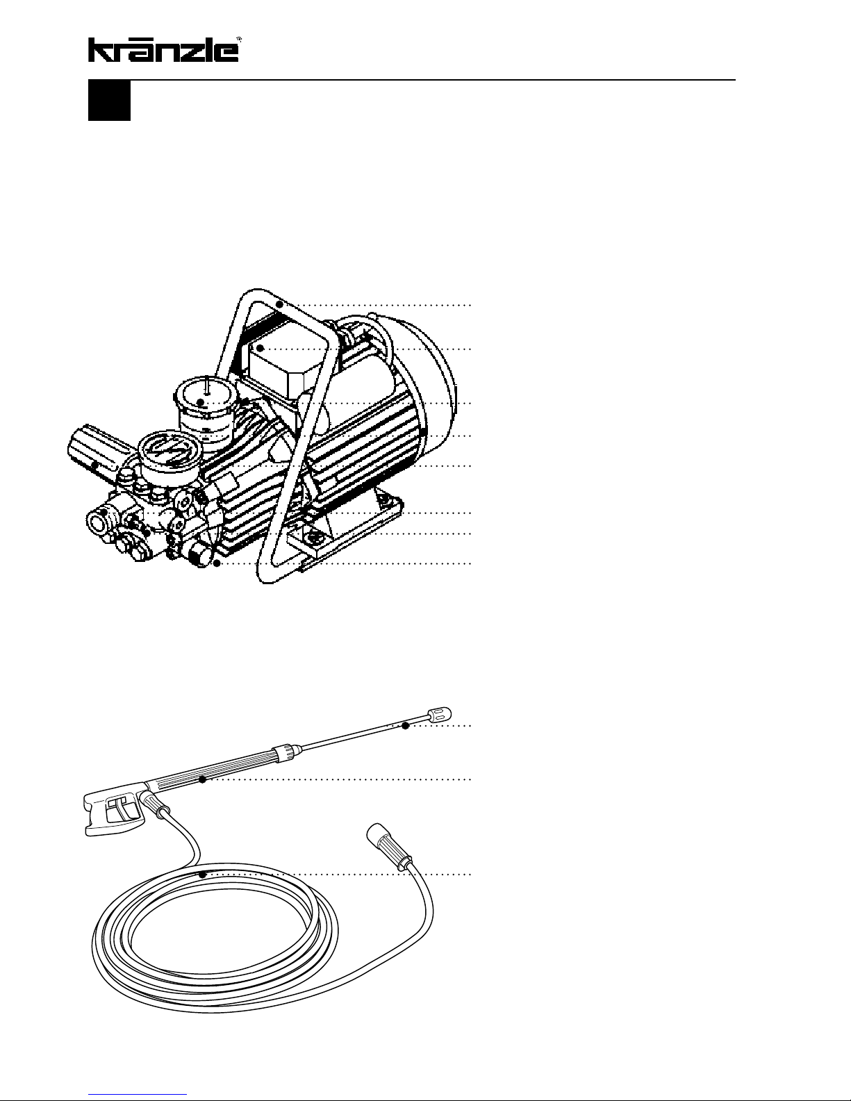
Description of appliance
Kränzle HD 9/80, HD 12/130
Ergonomically shaped handle
On/Off switch with motor protection
Oil filler neck
Large stainless steel manometer
Pressure control valve – safety valve
with continuously adj. pressure control
High pressure outlet
High pressure pump
Water intake with filter
Interchangeable steel lance with regulating
nozzle and/or Vario Jet nozzle
Trigger gun with safety catch
Steel braided high-pressure hose, 10 m
2
Page 3

Contents
Page
3
Description .......................................................................................... 2
Contents .......................................................................................... 3
Technical data ........................................................................................ 4
Overview “This is what you have purchased” ........................................... 6
General rules ......................................................................................... 7
Safety precautions – accident prevention ............................................ 8
Please note - important: Connection to water supply - electrical connection
....... 10
Kränzle- technology .............................................................................. 12
Water and cleaning system ................................................ 12
Lance and spray gun ......................................................... 12
Pressure control valve – safety valve ................................. 12
Motor protecting switch ..................................................... 13
High-pressure hose and spray device ....................................... 13
Total stop system .............................................................. 13
Putting into operation ........................................................................ 14
Connection to water mains ................................................ 14
Direct suction ................................................................... 17
When using detergents ..................................................... 18
To shut down the pump / frost protection ............................................... 19
Small repairs – do it yourself! ............................................................... 20
Inspections – inspection reports ............................................................ 24
Guarantee ........................................................................................ 25
Accessories for high-pressure cleaners ................................................. 26
Spare parts list ................................................................................... 28
Complete assembly ........................................................... 28
Valve housing ................................................................... 30
Unloader valve and pressure switch .................................. 32
Transmission .................................................................... 34
Motor ................................................................................ 36
Gun with lance .................................................................. 38
Wiring diagrams ................................................................................... 40
Inspections – inspection reports ............................................................ 42
Page 4
4
Technical data
Technical data Kränzle HD 9/80 Kränzle 12/130
Operating press. continuously adj. 10 - 80 bar 10 - 130 bar
Nozzle size 042 042
Permissible overpressure 90 bar 145 bar
Water output 9 l/min 11.4 l/min
at 1.400 r.p.m. at 1.400 r.p.m.
Inlet water temperature max. 60 °C max. 60 °C
Suction height 1.0 m 1.0 m
Steel-weave high-pressure hose 10 m 10 m
Connected load
230 V~, 7.5 A, 50 Hz 230 V~, 13 A, 50 Hz
Power input P 1 - 1.6 kW P 1 - 2.9 kW
Power output P 2 - 1.0 kW P 2 - 2.2 kW
Weight 19 kg 32 kg
Dim. incl. pulling handle in mm 440 x 200 x 350 350 x 330 x 900
Sound level acc. to DIN 45 635 86 dB (A) 86 dB (A)
Acoustic power LWA 84 dB (A) 91 dB (A)
Recoil at lance approx. 18 N approx. 20 N
Vibration at lance 1.9 m/s
2
2.1 m/s
2
Order no. 41,171 41,168
Permissible tolerance for figures ± 5 % acc. to VDMA uniform sheet 24411
Page 5

5
Page 6
6
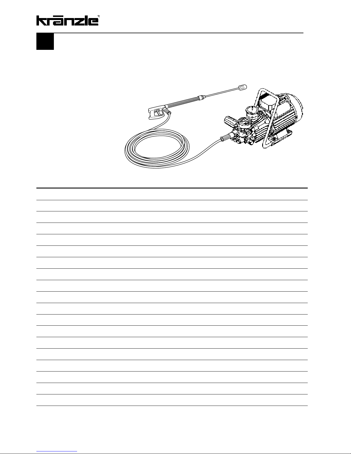
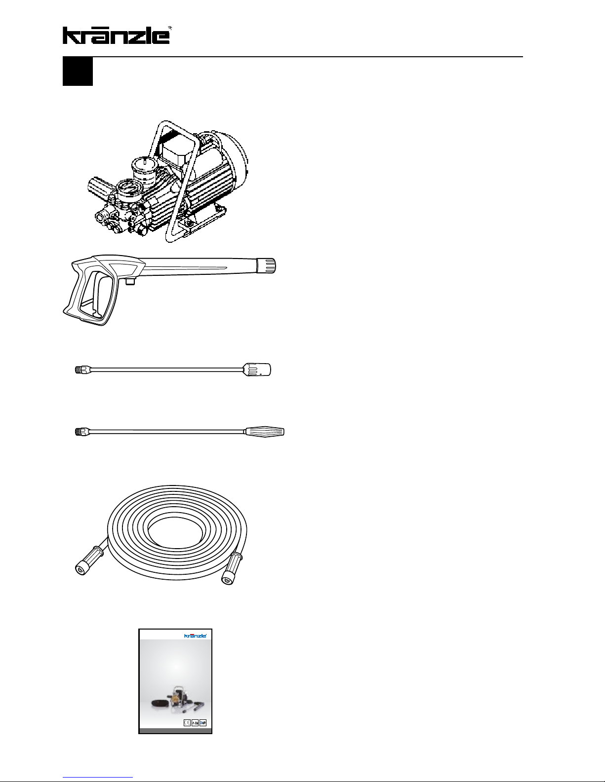
This is what you have purchased
1.
High-pressure cleaners
Kränzle 9/80 or 12/130
2.
Gun with safety catch
3.
Spray lance with regulating nozzle and
high pressure nozzle, flat jet 25042
HD 12/130
4.
Lance with Vario-Jet nozzle
HD 9/80
5.
Steel-weave high-pressure hose,
10 m, NW 6
6.
Operating manual
www.kraenzle.com
Page 7

Oil leakage: If oil leaks contact your nearest after-sales service
(dealer) at once. (Ecological damage, damage to the transmission)
In case of increased humidity or fluctuations in temperature
development of condensed water is possible; if the oil turns
grey, you must change it.
Range of application
Use machines for cleaning tasks with high-pressure water jet and detergents or with
high-pressure water jet without detergents only.
7
General rules
Explanatory symbols used in the operating instructions
High-pressure jets can be dangerous when used
incorrectly. The jet must not be directed at people, animals, live electrical
equipment, or the achine itself
Pictogram used on the unit
F
Precautions
Precautions contain useful remarks of the manufacturer in order to remedy
potential problems.
Warnings
Warnings contain instructions of the manufacturer to be strictly followed by
the user. Such instructions serve to illustrate cases of incorrect use of the
machine as they occur time and again and which can lead to severe bodily
harm or death.
Oil change:
The first oil change should be carried out after approximately 50 operating hours, then
every year or after 1000 operating hours. If the oil turns grey or white, you must change
the oil of your high-pressure pump in any casen.
If it becomes necessary to change the oil, open the oil discharge screw and drain the
unit over a collection reservoir. The oil is to be caught in the reservoir and disposed of in
an approved manner.
New oil:
0,25 l - Kränzle gear oil (40.092 2) or W 15/40.
Page 8
8
Safety precautions
Accident prevention
The machine is designed for accidents to be impossible if used correctly. The operator is
to be notified of the risk of injury from hot machine parts and the high-pressure water jet.
The “Guidelines for Liquid Spray Devices” must be complied with.
Always make sure to disconnect the power supply cable
prior any cleaning, maintenance or servicing!
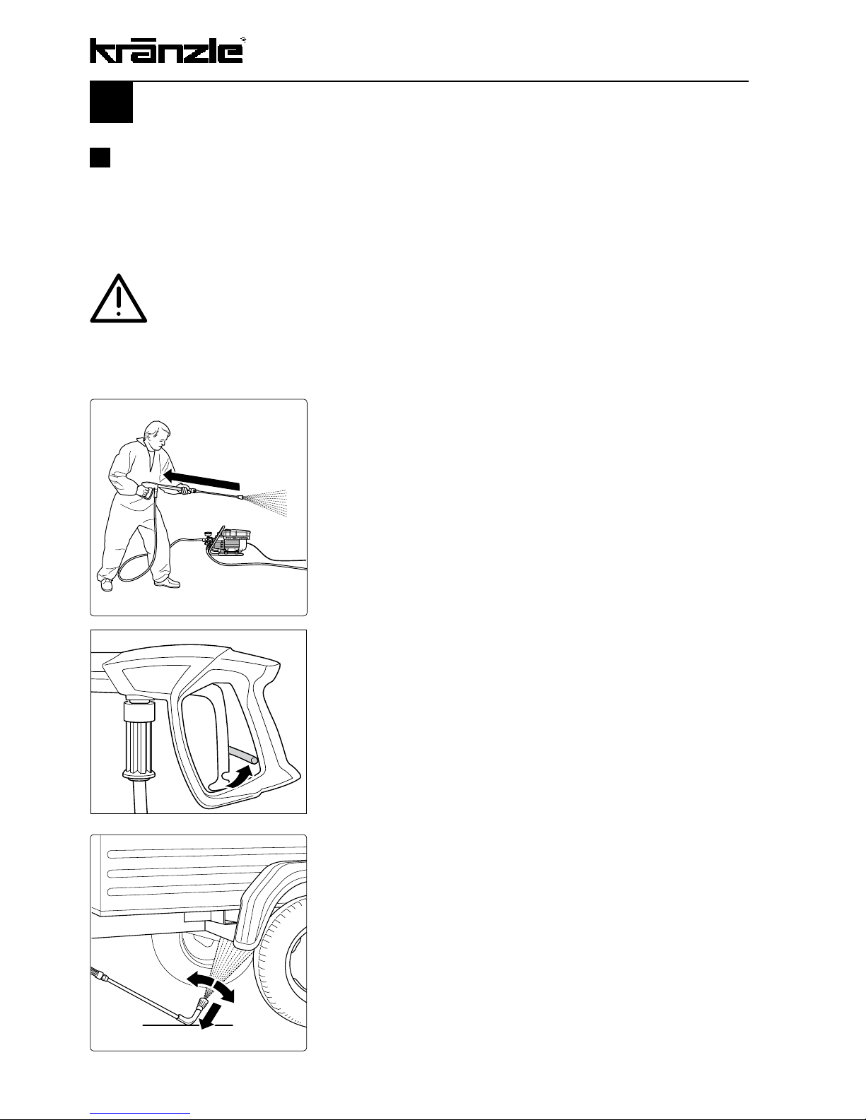
Bear in mind that during cleaning tasks with
a high-pressure water jet a significant recoil
at the lance arises (see technical data on
page 4).
Apply the safety catch on the spray gun
after each use, in order to prevent
unintentional spraying!
Always aim the underbody lance! Bear in
mind when using a curved or angled
spraying lance that there is a significant
amount of torque in the recoil!
Page 9
Safety precautions – This is prohibited!
9
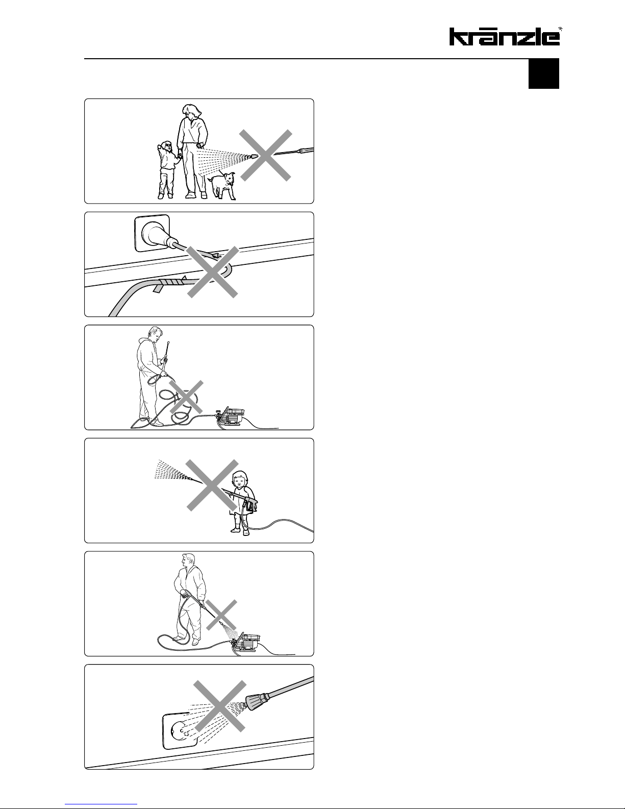
Never allow children or untrained
persons
to use the high pressure cleaner!
Never direct the water jet at the
machine itself!
The machine may not be placed
within reach of the water jet spray
mist!
Do not direct the water jet at power
sockets or live electrical equipment!
Never direct the high-pressure jet at
yourself or at others, not even to clean
clothes or shoes.
Do not operate this machine in the vicinity
of persons without protective clothing.
Never direct the water jet at people, animals,
power sockets or any other electrical
installations!
High pressure jets can be dangerous in case
of improper use!
Never pull the high-pressure hose if it
has formed kinks or “nooses”!
Never pull the hose over sharp edges!
Page 10
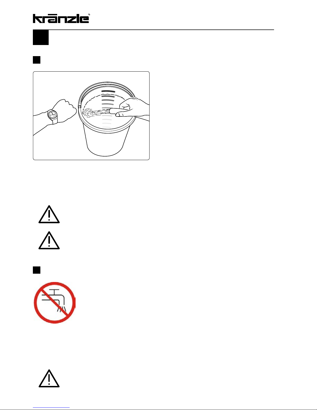
Lack of water occurs more often than you
probably believe. The more powerful a high
pressure cleaner is the greater is the danger that a lack of water occurs. If there is
only an insufficient amount of water available, cavitation arises inside the pump, which
is normally noticed too late or even not at
all.The pump will be destroyed.
Please check the available quantity of water
by filling a bucket with liter scale for 1/2
minute
.
The following minimum quantity of water is necessary for a safe and problem-free
operation of the high-pressure cleaner: HD 9/80: 9 l/min, HD 12/130: 11,4 l/min
Please note - important!
If the metered quantity of water is too small, you have to use a different water connection, guaranteeing the necessary output.
Lack of water leads to an accelerated wear of the joints (no guarantee).
Lack of water
10
Water supply
Please pay attention to the regulations of your waterworks company. In
accordance with DIN EN 61770, the machine may not be directly
connected to the public drinking water supply lines. A brief connection
however is permissible according to DVGW (German Association for
Gas and Water Affairs) if a non-return valve with tube ventilator
(Kränzle order no. 41.016 4) is built into the water supply. Also indirect
connection to the public drinking water supply lines is permissible by way of free
emission in accordance with EN 61 770; e.g. by using a reservoir with a float valve.
Direct connection to a non-drinking water supply line is permissible.
Once the water has passed through the non-return valve, it is no longer
considered to be drinking water.
Page 11
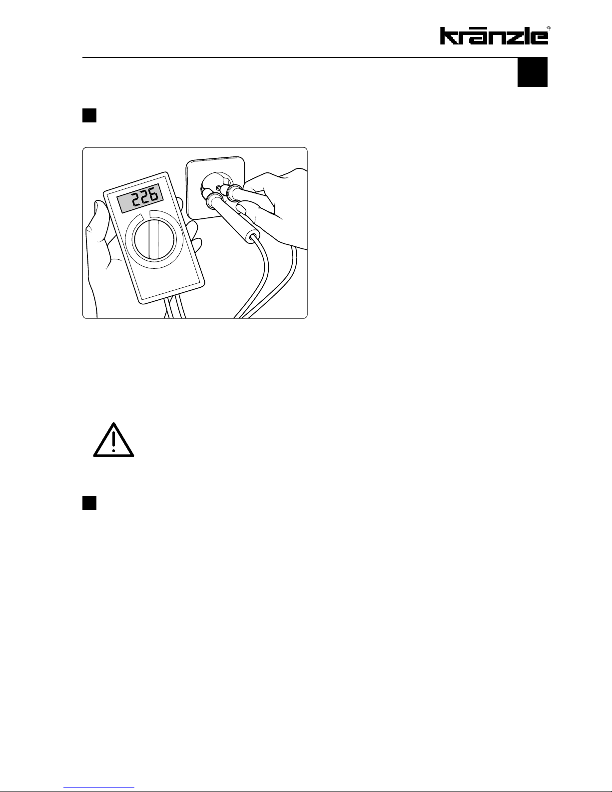
Insufficient quantity of electricity
If there are too many collectors in your
proximity connected to the network at the
same time, the available voltage and the
current intensity may decline.
Consequently the motor of the high-pressure cleaner does not start or even blows.
The power supply may also be insufficient
if the power cable is too long or too thin. If
extension cables are too long, this may
lead to a voltage drop causing malfunc
tions or start-up difficulties.
HD 9/80: 230 V, 7.5 A, 50 Hz HD 12/130: 230 V, 13 A, 50 Hz
Check the line fusing and have the voltage and the available current
intensity checked by an expert in case of uncertainty.
11
Electrical connection
The machine is supplied with a 5 m long electrical power cable with plug. The mains plug
must be fitted to a standard grounded socket with a 30mA residual current operated
device. The socket must be protected with a 16 A delay action fuse on the mains side.
When using an extension cable, this must have an earthed lead which is properly connected to the socket. The conductors in the extension cable must have a minimum cross
section of 1.5 mm².
Plug connections must be of a spray-proof design, and may not be located on a wet
floor. With extension cables of more than 10 m the minimum cross section must be 2.5
mm! When using a cable reel always make sure that cable is completely unrolled.
Page 12

Kränzle technology
12
Water and Cleaning System
Water can be connected at mains pressure to the high pressure pump or it can be
sucked directly from a storage tank. The water is then forced under pressure by the high
pressure pump to the lance. The high pressure jet is formed by the nozzle at the end of
the lance.
Environmental, refuse disposal and water protection
regulations must be observed!
Lance with trigger gun
The machine can only be operated when the safety trigger is squeezed. When the lever
is squeezed, the spray gun opens. The liquid is then pumped to the nozzle. The spray
pressure increases and quickly reaches the selected operating pressure. When the
trigger is released, the trigger gun closes and any further spraying of liquid from the
lance is stopped. The pressure gauge must show 0 bar.
The increase in pressure when the trigger gun is closed causes the pressure control
valve-safety valve to open. The motor is switched off by the pressure switch. When the
trigger gun is opened, the pressure control valve - safety valve closes, the motor is
started and the pump resumes pressure spraying from the lance with the selected
operating pressure.
The trigger gun is a safety device. Repairs should only be
performed by qualified persons. Should replacement
parts be required, use only components authorized by
the manufacturer.
Pressure control valve - safety valve
The pressure control valve - safety valve protects the machine from a build up of
excess pressure, and is designed not to permit an excess pressure to be selected for
operation. The limit nut on the handle is sealed with a spray coating. The operating
pressure and spray rate can be steplessly adjusted by turning the handle
.
Replacements, repairs, new adjustments and sealing
should only be performed by qualified persons.
In order to guarantee the safety of the machine, only
manufacturer's original replacement parts or manufacturer approved replacement parts should be used.
Page 13
Motor protection switch
The motor is protected from overload by a motor protection switch, which cuts out the
motor in the event of overload. However should the switch trip frequently, the cause of
the malfunction should be located and rectified (see page 11).
Replacements and inspection work should only be perfor-
med by qualified persons when the machine is discon-
nected from the power supply, i.e. with plug pulled out
from the electrical socket.
High pressure hose and spray device
The high pressure hose and spraying device supplied with the machine are made of high
grade material, they are also optimised for the machine and marked as required by the
appropriate regulations. (max. hose length 20 m)
All high pressure hoses, fittings and couplings are safety
component parts; therefore only manufacturer approved
and properly labeled component parts are to be used for
replacement. The high pressure hose and spray device
must be connected in a pressure-tight manner (without
leakage).
The high pressure hose may not be driven over, pulled
excessively, or twisted.
The hose may under no circumstances be pulled over
sharp edges.
13
Page 14
Setting up – Location
Neither set up or operate the machine in rooms where
there is a risk of fire or explosion nor put it into puddles.
Do not use the machine under water.
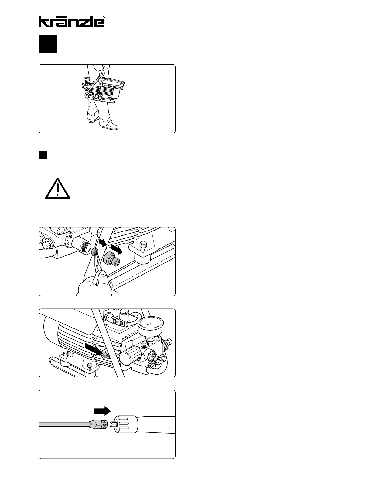
Putting into operation
4.
Push on lance to gun.
2.
Check water inlet filter for cleanliness prior to putting the machine
into operation. Manually unscrew
hose attachment. Take out the serial
water inlet filter using needle nose
pliers and clean if filter is soiled.
1.
Move high-pressure cleaner to the job
site.
Kränzle high pressure cleaners are
very compact and easily portable
machines.
3
. Each time check oil level at oil-level
glass prior to putting HP cleaner
into operation.
The oil level must be visible in the midd-
le of the oil level glass.
14
Page 15

6.
Unwind high-pressure hose straight
and without nooses. (When using hose
extensions take care that the max.
length of 20 m is not exceeded!)
7.
Push on HP hose to gun.
8.
Screw together HP hose and gun.
9.
Connect water hose to water tank. The
cleaner may be connected to water
mains with cold or 60°C warm water.
Alternatively water can be sucked in
from a containe.
5.
Screw together lance and gun.
Be careful when using hot water!
When running your high pressure cleaner with hot water
of 60° C raised temperatures occur. Do not touch the
metal parts of the cleaner without safety gloves!
15
Page 16

Putting into operation
11.
Steplessly adjust operating pressure
with handwheel. The maximum pressure is adjusted ex work.
Kränzle HD 9/80: 80 bar
Kränzle HD 12/130: 130 bar
12.
Ventilation of the machine: Pull and
release the trigger several times.
Switch on high-pressure cleaner with
opened spray gun. Start cleaning
task.
Caution: Units may be operated in
horizontal position only!
10.
Connect to circuit.
Kränzle HD 9/80:
230 V ~, 7.5 A, 50 Hz
Kränzle HD 12/130:
230 V ~, 13 A, 50 Hz
The socket must be protected with a
16 A delay action fuse on the mains
side.
16
Page 17

Direct suction
Drawing water from ponds, rainwater tanks, etc.
Due the suction capacity of its pump (up to 1 m suction height) this high-pressure cleaner can suck in water for cleaning purposes from separate containers or ponds.
Mount suction hose with suction filter
(Kränzle accessories No. 15.038 3).
When using other hoses the inner cross
section of the hose must be at least
3/4” = 16 mm.
Use clean water only!
Prior to starting the first suction the pump resp. the
suction hose has to be filled with water!
17
Page 18

Suction of detergents
When using cleansing agents
Suction of detergents by means of the detergent injector is only possible if a lance with
regulating nozzle or the Vario Jet lance are fitted. The lance must be set to low pressure.
1.
Put injection hose with filter into container with cleansing agent.
2.
Switch on machine with opened trigger
gun and set lance regulating nozzle to
low pressure.
With Vario-Jet lance: To reach the low
pressure push Vario nozzle to the front
so that the injector can suck in the
cleansing agent.
3.
Let cleansing agent take effect and
then spray off with a high-pressure jet.
The chemicals supply is automatically
stopped by setting the regulating nozzle to high pressure or when pushing
the Vario nozzle backward.
18
Safety precautions for the handling of cleansing agents
The pH value neutral 7-9 is prescribed for the detergents .
This machine has been designed for the use of cleansing agents as
supplied and recommended by the manufacturer. The use of any
other type of cleansing detergents or chemicals may impair the
safety of the machine.
Observe specifications of detergent manufacturer!
e.g.: protective equpment, rules for waste water treatment etc.
Page 19

To shut down the pump
01.
Switch off the machine
02.
Cut off the water supply
03.
Open the spray gun briefly until the pressure is released
04.
Apply the safety catch on the spray gun
05.
Remove the water hose and spray gun
06.
Drain the pump: switch on the motor for approx. 20 seconds
07.
Pull the plug from the socket
08.
Clean HP hose and wind up
09.
Clean power cable and wind up
10.
Clean water filter
11.
Winter: store the pump in rooms above 0°C
Due to their compact and space saving
design these Kränzle cleaners can be
stored practically anywhere.
Store in a place-saving manner
19
After contact with the cleansing agent, immediately rinse your skin
with plenty of clean water.
Never suck in flammable liquids like varnish solvents, petrol, oil or
similar liquids!
Observe specifications of detergent manufacturers!
Seals inside the appliance are no resistant against solvents! The spray
mist of solvents is highly inflammable, explosive and poisonous.
DANGER OF EXPLOSION!!!
To shut down the pump
Page 20

20
Small repairs
do it yourself!
No water from the nozzle but the gauge shows full pressure:
Most likely inlet sieve or nozzle are blocked.
Caution! Pull plug from socket prior to starting
any repair work!
If this procedure is not successful, the nozzle has to be dismantled and cleaned or even
replaced, if necessary.
The pressure gauge shows full pressure,
but from the nozzle comes only little water
or no water at all.
(Inside the pressure gauge is no water but
a filling with glycerin to damp the vibration
of the pointer.)
Switch off the cleaner. Pull plug from the
socket. Operate gun seveal times to
decrease the pressure.
First unscrew gun and lance, then rinse
hose from any residues.
Check water inlet filter for soiling.
If the problem still exists, take wire (paper
clip) and push through nozzle opening.
Page 21

Pressure gauge shows little pressure, the water from the nozzle
comes in squirts: Most likely the valves are soiled.
The pressure gauge shows little pressure
despite fully turned up pressure regulation.
The water from the lance comes in squirts.
The HP hose vibrates.
(Inside the pressure gauge is no water but
a filling with glycol to damp the vibration of
the pointer.)
Proceeding:
Switch off the cleaner. Pull plug from the
socket. Operate gun seveal times to
decrease the pressure.
Unscrew all 6 valves, one after the other
(hexagonal brass screws, 3 in a row,
vertically and horizontally).
Take out valve body (with green or red plastic
coating) and O-ring by means of needle nose
pliers.
Check O-ring for damage. In case of a
damage the O-ring has to be replacedn.
Take a wire (paper clip) and clean valves
under running water. Also clean valve seat
inside the pump.
Do not forget the O-ring during reassembly!
21
Page 22

Small repairs
do it yourself!
The pressure gauge shows full pressure although the gun has
been closed. The pressure switch valve switches constantly.
Possible cause no.1: Leakage
Having closed th gun, the HP cleaner must
shut down and the pressure gauge must
show „0“ bar.
If the pressure gauge still shows full pressure and the motor constantly switches on
and off, the possible reason for this can be
a leakage of the pump, the HP hose or the
lance.
Proceeding:
Check the connections from the HP cleaner to the the HP hose, from the hose to
the gun and also the connection between
lance and gun for tightness.
Switch off the cleaner. Shortly pull the trigger of the gun to decrease the pressure.
Unscrew HP hose, gun and lance and
check the O-rings.
If the O-rings are damaged they have to
be replaced.
Bei Leckage wird für eventuelle Folgeschäden keine
Garantie übernommen.
22
Page 23

Possible cause no. 2: The return body is soiled or the sealing ring on
the return body is defective.
Proceeding:
Switch off machine and pull plug from
socket. Stop water supply. Unscrew pump
outlet.
The pressure gauge shows full pressure although the gun has
been closed. The pressure switch valve switches constantly.
Caution ! There is no guarantee if the pump is damaged
by defective O-rings due to air induction or lack of water
(cavitation).
23
Replace non-return valve if necessary.
Take out check ball and check for soiling
or damage of ball or stainless steel seat
inside the pump housing.
Page 24

Kränzle HD 9/80, HD 12/130
Manfred Bauer, Fa. Josef Kränzle
Rudolf-Diesel-Str. 20, 89257 Illertissen
HD 9/80: 540 l/h; HD 12/130: 660 l/h
Machinery directive 2006/42/EC
EMC-directive 2004/108/EC,
Noise directive 2005/88/EC, Art.13
HP water spraying machines annex 3,
part B, chapter 27
89 dB (A)
91 dB (A)
Annex V, noise directive 2005/88/EC
EN 60 335-2-79 :2009
EN 55 014-1 :2006
EN 61 000-3-2 :2006
EN 61 000-3-3 :2008
EC declaration of conformity
Hereby we declare that:
technical specifications available from:
Nominal volume ow rate:
comply with the following guidelines
and their amendments for high-pressure
cleaners:
Sound level measured:
Sound level guaranteed:
Applied conformity evaluation procedures:
Applied specifications and standards:
I. Kränzle GmbH
Elpke 97 D - 33605 Bielefeld
Bielefeld, 03.09.12
24
Kränzle Josef
(Managing director)
Page 25

Guarantee
The guarantee is only valid for material and manufacturing errors.
Wearing does not fall within this gurantee.
The instructions in our operating manual must be complied with. The operating instructions form part of the guarantee.
For high-pressure cleaners sold to the user the guarantee period is 24 month.
For high-pressure cleaners sold for industrial use the guarantee period is 12 month.
In the case of a guarantee please contact your dealer or authorized seller delivering
accessories and your purchase receipt. You can fin them in the internet under
www.kraenzle.com.
The guarantee is also void if the machine is used with exceeding the temperature and
speed limits, a voltage below the required rating, with less than the required amount of
water or with dirty water.
Pressure gauge, nozzle, valves, sleeves, high pressure hose and spray equipment are
wear parts and are not covered by the warranty
25
Page 26

Versatile due to Kränzle accessories
Rotating washing brush with 400 mm
extension, Order no. 41,050 1
Underbody lance with 800 mm extension, Order no. 41,075
Dirtkiller lance
(rotating point jet nozzle with intensive
cleaning effect)
Please specify type of appliance when
ordering.
26
Page 27

Suction hose with intake filter
Order no. 15,038 3
Spray guard
Order no. 41,052
27
Pipe cleaning hose with nozzle,
10 m - Order no. 41 058 1
15 m - Order no. 41 058
20 m - Order no. 41 058 2
25 m - Order no. 41 058 3
Page 28

Kränzle HD 9/80
Complete assembly
28
Position Description Qty. Ord.-No
2 Gummiprol 2 41.098 1
3 Tragebügel BG 80 1 44.581
4 Senkschraube M6x20 1 43.473 1
5 Netzanschlusskabel 1 41.092
6 Scheibe 8,4 4 41.409
7 Mutter DIN985 M8 4 41.410
8 HD-Schlauch 1 43.416
9 O-Ring 9,3 x 2,4 2 13.273
10 Gummipuffer 30 x 20 4 46.023 1
11 Pistole M2000 1 12.480
12 Vario-Jet 042 Lanze 1 41.156 8-042
Page 29

29
Kränzle HD 12/130
Complete assembly
Position Description Qty. Ord.-No
1 Chemiesaugschlauch mit Filter 1 15.038
2 Gummiprol 2 41.098 1
3 Tragebügel BG 90 1 41.098
4 Senkschraube M6x20 1 43.473 1
5 Netzanschlusskabel 1 41.092
6 Scheibe 8,4 4 41.409
7 Mutter DIN985 M8 4 41.410
8 HD-Schlauch 1 43.416
9 O-Ring 9,3 x 2,4 2 13.273
10 Gummipuffer 30 x 20 4 46.023 1
11 Pistole M2000 1 12.480
12 Regeldüse 20042 (HD 12/130 S) 1 12.701-M20042
Page 30

Kränzle HD 8/90, HD 12/130
Valve housing
30
Position Description Qty. Ord.-No
Reperatur - Sätze:
Rep.-Satz Ventile für APG-Pmpe 41.748 1
bestehend aus je 6x Pos. 4; 6x Pos. 5; 6x Pos. 6
Rep.-Satz Manschetten 18 mm 41.049 1
bestehend aus je 3x Pos. 27; 3x Pos. 28;
3x Pos. 28.1; 6x Pos. 29; 3x Pos. 30
Page 31

Valve housing
Position Description Qty. Ord.-No
31
1 Ventilgehäuse APG 1 42.160 3
für 18 mm Plunger-Durchmesser
2 Ventilstopfen 5 41.714
2.1 Ventilstopfen mit R1/4“ IG 1 42.026 1
3 Dichtstopfen M 10 x 1 1 43.043
4 Ventile (grün) für APG-Pumpe 6 41.715 1
(große Ausführung Ventile)
5 O-Ring 16 x 2 8 13.150
6 O-Ring 15 x 2 6 41.716
7 Dichtstopfen R 1/4“ mit Bund 1 42.103
8.1 Ausgangsteil (TS) 1 40.522 2
9 Dichtstopfen M 8 x 1 2 13.158
10 O-Ring 18 x 2 1 43.446
11 Aluminium - Dichtring 3 13.275
12 Stopfen 1/4“ AG mit ISK 1 13.387
13 O-Ring 11 x 1,5 1 12.256
14 Edelstahlsitz Ø 7 1 14.118
15 Sprengring 1 12.258
16 Edelstahlkugel Ø10 1 12.122
17 Rückschlagfeder „K“ 1 14.120 1
27 Druckring 3 41.018
28 Manschette 18 x 26 x 4/2 3 41.013
28.1 Gewebemanschette 18 x 26 x 4/2 3 41.013 1
29 Backring 6 41.014
30 O-Ring 28,3 x 1,78 3 40.026
31 Leckagering 3 41.066
32 Zwischenring 3 41.015 2
33 Verschlussstopfen R3/8“ 1 14.113
34 Kupferring 17 x 22 x 1,5 1 40.019
37 Verschlussschraube M10x1 1 13.385
38 O-Ring 6x1,5 2 13.386
39 Saugzapfen Schlauchanschluss 1 13.236
40 Edelstahlkugel 5,5 mm 1 13.238
41 Edelstahlfeder 1 13.239
42 Usit-Ring 1 42.104
43 Innensechskantschraube M 8 x 30 2 41.036 3
44 Innensechskantschraube M 8 x 55 2 41.017 2
46 Sauganschluss 1 41.016
47 Wasserlter 1 41.046 1
48 Gummidichtrung 1 41.047 1
49 Steckkupplung 1 41.047 2
50 O-Ring 1 41.047 3
Page 32

Kränzle HD 9/80, HD 12/130
Unloader
32
Page 33

33
5 O-Ring 16 x 2 1 13.150
5.1 O-Ring 13,94 x 2,62 1 42.167
8 O-Ring 11 x 1,44 1 12.256
9 Edelstahlsitz 1 14.118
10 Sicherungsring 1 13.147
11 Edelstahlkugel 1 13.148
12 Edelstahlfeder 1 14.119
13 Verschlussschraube 1 14.113
14 Steuerkolben 1 14.134
15 Parbaks 16 mm 1 13.159
16 Parbaks 8 mm 1 14.123
17 Spanstift 1 14.148
18 Kolbenführung spezial 1 42.105
19 Kontermutter M 8 x 1 2 14.144
20 Ventilfeder schwarz 1 14.125
21 Federdruckscheibe 1 14.126
22 Nadellager 1 14.146
23 Handrad 1 14.147
25 Elastic-Stop-Mutter M 8 x 1 1 14.152
26 Manometer 0-250 Bar 1 15.039
27 Aluminium-Dichtring 2 13.275
50 O-Ring 3,3 x 2,4 1 12.136
53 O-Ring 14 x 2 1 43.445
54 Parbaks 4mm 1 12.136 2
57 Blindverschluss mit Dichtungen 1 44.551
58 Parbaks 7mm 1 15.013
70 Guide piston with handwheel 43.444
Position Description Qty. Ord.-No
Page 34

34
Kränzle HD 9/80
Transmission
1 Gehäuseplatte für 18 mm Plunger 1 41.020 2
2 Öldichtung 18 x 28 x 7 3 41.031
3 O-Ring Viton 88 x 2 1 41.021 1
4 Plungerfeder 3 41.033
5 Federdruckscheibe 18 mm 3 41.034
6 Plunger 18 mm 3 41.032 1
7 Sprengring 18 mm 3 41.035
8 Taumelscheibe 9,5° 1 41.028-9,5
10 Axial-Kugellager 3-teilig 1 43.486
12 Innensechskantschraube M 8 x 30 4 41.036 1
13 Ölschauglas 1 42.018 1
14 O-Ring 14 x 2 2 43.445
16 Ölverschlussschraube rot 1 43.437
20 O-Ring 14 x 2 1 43.445
21 Ölablassstopfen M18x1,5 mit Magnet 1 48.020
Position Description Qty. Ord.-No
Page 35

Kränzle HD 12/130
Transmission
Position Description Qty. Ord.-No
35
1 Gehäuseplatte für 18 mm Plunger 1 41.020 2
2 Öldichtung 18 x 28 x 7 3 41.031
3 O-Ring Viton 88 x 2 1 41.021 1
4 Plungerfeder 3 41.033
5 Federdruckscheibe 18 mm 3 41.034
6 Plunger 18 mm 3 41.032 1
7 Sprengring 18 mm 3 41.035
8 Taumelscheibe 12,0° (HD 12/130) 1 41.028-12,0
10 Axial-Kugellager 3-teilig 1 43.486
12 Innensechskantschraube M 8 x 30 4 41.036 1
13 Ölschauglas 1 42.018 1
14 O-Ring 14 x 2 2 43.445
18 Ölkelch 1 41.022
19 Deckel für Ölkelch 1 41.023
21 Ölablassstopfen M18x1,5 mit Magnet 1 48.020
Page 36

36
Position Description Qty. Ord.-No
Kränzle HD 9/80
AC motor
1 Ölgehäuse BG 80 1 41.074 4
2 Stator BG 80 1 23.001
230V/50Hz 1,0kW 1400 U/min
3 Rotor BG 80 Silumin 1 43.104
4 Passfeder 1 41.483 1
5 Kugellager 1 43.025
6 Motor-Lager Schulterlager 7304 1 41.027
7 Schelle für Lüfterrad 1 44.534 1
8 Öldichtung 25 x 35 x 7 1 41.024
9 Lüfterrad 1 44.534
10 Lüfterhaube 1 41.497
11 Flachdichtung 1 41.086 1
12 Lüsterklemme 2-polig 1 43.031
13 Schaltergehäuse 1 41.090
16 Kabelverschraubung PG 11 mit Knickschutz 1 41.091
17 Kabelverschraubung PG 9 1 41.087
18 Kondensator 40 µF 1 43.035
20 Blechschraube 3,5 x 9,5 2 41.088
21 Blechschraube 2,9 x 16 2 43.036
22 Blechschraube 4,8 x 16 4 40.282
23 Blechschraube 3,9 x 9,5 4 41.079
24 Erdungsschraube kpl. 1 43.038
25 Innensechskantschraube M6x 30 4 43.037
26 Netzanschlusskabel 1 41.092
27 Klemmrahmen mit Schalterabdichtung 1 41.110 5
28 Schalter mit 8,5 A Überstromauslöser 1 43.329
Page 37

Position Description Qty. Ord.-No
Kränzle HD 12/130
AC motor
37
1 Ölgehäuse BG 90 1 41.417
2 Stator BG 90 1 23.003
230V/50Hz 2,2 kW 1400 U/min
3 Rotor BG 90 1 43.316
4 Passfeder 1 41.483 1
5 Kugellager 1 43.317
6 Motor-Lager Schulterlager 7304 1 41.027
7 Öldichtung 25 x 35 x 7 1 41.024
8 Federscheibe 1 43.318
9 Lüfterrad 1 41.118 1
10 Lüfterhaube 1 41.120 1
11 Flachdichtung 1 41.086
12 Lüsterklemme 2-polig 1 43.031
13 Schaltergehäuse 1 41.090
14 Schelle für Lüfterrad 2 43.456
15 Vierkantmutter 2 43.323
16 Kabelverschraubung PG 11 mit Knickschutz 1 41.091
17 Kabelverschraubung PG 9 1 41.087
18 Kondensator 70 µF 1 43.322
19 Schraube M 4 x 12 2 41.489
20 Blechschraube 3,5 x 9,5 2 41.088
21 Blechschraube 2,9 x 16 1 43.036
22 Blechschraube 4,8 x 16 4 40.282
23 Blechschraube 3,9 x 9,5 4 41.079
24 Erdungsschraube kpl. 1 43.038
25 Innensechskantschraube M6x 30 4 43.037
26 Netzanschlusskabel 1 41.092
27 Klemmrahmen mit Schalterabdichtung 1 41.110 5
28 Schalter mit 13,5 A Überstromauslöser 1 41.110 7
Page 38

Trigger gun and regulating nozzle HD 12/130
Position Description Qty. Ord.-No
38
1 Pistolenschale rechts + links 1 12.450
2 Schraube 3,5 x 14 10 44.525
3 Reparatursatz M2000 12.454
18 O-Ring 9,3 x 2,4 1 13.273
30 ST 30-Nippel M 22 x 1,5 AG / M 12 x 1 1 13.363
31 Rohr 500 lang, bds. M12 x 1 1 41.527 1
32 Kunststoff-Hülse 1 13.202
33 Regeldüse ohne Hülse 1 43.439
34 Sprengring 1 43.441
35 O-Ring 6,0 x 3,0 1 14.121
36 HD-Düse MX20042 1 MX20042
36.1 HD-Düse M20030 1 M20030
37 Düsenhalter 1 26.004
Trigger gun M2000 compl. 12,480
Lance with regulating nozzle M20042 12,701-M20042
Page 39

Position Description Qty. Ord.-No
Trigger gun and Vario-Jet lance HD 9/80
39
1 Pistolenschale rechts + links 1 12.450
2 Schraube 3,5 x 14 10 44.525
3 Reparatursatz M2000 12.454
18 O-Ring 9,3 x 2,4 1 13.273
19 ST 30-Nippel M22x1,5 AG / M12x1 1 13.363
20 Rohr 500 lang, bds. M12 x 1 1 51.527 1
30 Klemmstück 1 41.155 2
31 Halterung für Klemmstück 1 41.155 4
32 Kunststoffhülle 1 41.155 1
33 Vario-Jet 042 1 41.155 6
Trigger gun M2000 compl. 12,480
Lance compl. with Vario-Jet 042 41,156 8-042
Page 40

Wiring diagram
40
Weber-Unimat WT 22 - 551
8,5 A ( HD 9/80),
13,5 A (HD 12/130 )
Motor stator
C : 40 µF ( HD 9/80)
C : 70 µF ( HD 12/130 )
Page 41

The appliance was checked by an expert according to the Guidelines for Liquid Spray
Equipment, the defects found have been rectified so that the Labour Safety can be
confirmed.
The appliance was checked by an expert according to the Guidelines for Liquid Spray
Equipment. The Labour Safety cannot be confirmed unless the defects found are rectified
by repair or replacement of the faulty parts.
The next retest according to the Guidelines for Liquid Spray Equipment has to be carried
out by: Month Year
Place, date Signature
Type plate (on hand)
Operating manual (on hand)
Protective covering, -device
Pressure line (tightness)
Pressure gauge (function)
Float valve (tightness)
Spraying device (marking)
HP-hose / connector (damage, marking)
Safety valve opens at 10 % / 20 % exceeding of operating pr.
Power cable (damage)
Protective conductor (connected)
On / Off switch
Used chemicals
Allowed chemicals
High-prsure nozzle
Operating pressure..................bar
Switch off pressure........ ........bar
Conductor reist. not exceeded / value
Insulation
Leakage current
Gun locked
HP cleaners for industrial use have to be checked by an expert every 12 months!
Inspection report on annually carried out Labour Safety Inspection (UVV) according to the Guidelines for Liquid
Spray Equipment. (This inspection sheet serves as proof for the completion of the retest and must be kept
carefully!)
Kränzle test seals: Order no. UVV200106
Scope of inspection o.k. yes no repaired
Inspection data determined value set value
Inspection result (tick)
Owner:
Address:
Type:
Serial no.:
Rep. order no.:
Inspection report for HP cleaners
41
Page 42

Type plate (on hand)
Operating manual (on hand)
Protective covering, -device
Pressure line (tightness)
Pressure gauge (function)
Float valve (tightness)
Spraying device (marking)
HP-hose / connector (damage, marking)
Safety valve opens at 10 % / 20 % exceeding of operating pr.
Power cable (damage)
Protective conductor (connected)
On / Off switch
Used chemicals
Allowed chemicals
High-prsure nozzle
Operating pressure..................bar
Switch off pressure........ ........bar
Conductor reist. not exceeded / value
Insulation
Leakage current
Gun locked
The appliance was checked by an expert according to the Guidelines for Liquid Spray
Equipment, the defects found have been rectified so that the Labour Safety can be
confirmed.
The appliance was checked by an expert according to the Guidelines for Liquid Spray
Equipment. The Labour Safety cannot be confirmed unless the defects found are rectified
by repair or replacement of the faulty parts.
The next retest according to the Guidelines for Liquid Spray Equipment has to be carried
out by: Month Year
Place, date Signature
HP cleaners for industrial use have to be checked by an expert every 12 months!
Inspection report on annually carried out Labour Safety Inspection (UVV) according to the Guidelines for Liquid
Spray Equipment. (This inspection sheet serves as proof for the completion of the retest and must be kept
carefully!)
Kränzle test seals: Order no. UVV200106
Scope of inspection o.k. yes no repaired
Inspection data determined value set value
Inspection result (tick)
Owner:
Address:
Type:
Serial no.:
Rep. order no.:
Inspection report for HP cleaners
42
Page 43

Type plate (on hand)
Operating manual (on hand)
Protective covering, -device
Pressure line (tightness)
Pressure gauge (function)
Float valve (tightness)
Spraying device (marking)
HP-hose / connector (damage, marking)
Safety valve opens at 10 % / 20 % exceeding of operating pr.
Power cable (damage)
Protective conductor (connected)
On / Off switch
Used chemicals
Allowed chemicals
High-prsure nozzle
Operating pressure..................bar
Switch off pressure........ ........bar
Conductor reist. not exceeded / value
Insulation
Leakage current
Gun locked
The appliance was checked by an expert according to the Guidelines for Liquid Spray
Equipment, the defects found have been rectified so that the Labour Safety can be
confirmed.
The appliance was checked by an expert according to the Guidelines for Liquid Spray
Equipment. The Labour Safety cannot be confirmed unless the defects found are rectified
by repair or replacement of the faulty parts.
The next retest according to the Guidelines for Liquid Spray Equipment has to be carried
out by: Month Year
Place, date Signature
HP cleaners for industrial use have to be checked by an expert every 12 months!
Inspection report on annually carried out Labour Safety Inspection (UVV) according to the Guidelines for Liquid
Spray Equipment. (This inspection sheet serves as proof for the completion of the retest and must be kept
carefully!)
Kränzle test seals: Order no. UVV200106
Scope of inspection o.k. yes no repaired
Inspection data determined value set value
Inspection result (tick)
Owner:
Address:
Type:
Serial no.:
Rep. order no.:
Inspection report for HP cleaners
43
Page 44

I. Kränzle GmbH
Elpke 97
D - 33605 Bielefeld
Subject to technical modifications. Order no 30.812 1
Reprint only allowed with the authorisation of Kränzle.
As date of 01.04.2014
 Loading...