

Page 1

Operating manualOperating manual
Operating manualOperating manual
Operating manual
Read and conform Read and conform
Read and conform Read and conform
Read and conform
safety instructions safety instructions
safety instructions safety instructions
safety instructions
before use before use
before use before use
before use
High Pressure Cleaners
GB
HDHD
HDHD
HD
7/1207/120
7/1207/120
7/120
HDHD
HDHD
HD
10/12010/120
10/12010/120
10/120
Page 2

2
Dear customer
We would like to congratulate you on your new high pressure cleaner and to thank
you for the purchase.
To ease your introduction to the use of the cleaner, we have provided the following
pages of explanations, tips and hints, which we ask you to read before using it for
the first time.
The equipment will assist you professionally in all cleaning tasks, e.g.:
Description
Zulässige Abweichung der Zahlenwerte ± 5 % nach VDMA Einheitsblatt 24411
Technical
data
Operating pressure,
steplessly adjustable
Nozzle size
Perm. overpressure
Water output
Hot water input (1-8 bar)
Suction height
High pressure hose
Electrical ratings
Connect. wattage input
output
Weight
Dimensions in mm
Sound level acc.to DIN 45 635
with dirtkiller
Sound level L
WA
Recoil at lance
Vibrations at lance
with dirtkiller
Kränzle
HD 7/120
10 - 120 bar
20 03
135 bar
at 1400 rpm 7 l/min
max. 60 °C
1.0 m
10 m
230V ; 50 Hz ; 7,5 A
P1: 1.6 kW
P2: 1.0 kW
18,5 kg
300 x 330 x 800
71 dB (A)
84dB (A)
84 dB (A)
ca. 27 N
1.9 m/s²
Order n°:
41.720
41.720 1
*
Muß dem Gerät mindestens zugeführt werden (Siehe Seite 7)
*
Kränzle
HD 10/120
10 - 120 bar
20 045
135 bar
at 2800 rpm 10 l/min
max. 60 °C
1.0 m
10 m
230V ; 50 Hz ; 11 A
P1: 2.5 kW
P2: 1.8 kW
18,5 kg
300 x 330 x 800
71 dB (A)
91 dB (A)
91 dB (A)
ca. 27 N
1.9 m/s²
Order n°:
41.721
41.721 1
- facades
- flagstones
- terraces
- vehicles of all types
- containers
- machines etc.
- removing of
old paint
Page 3
3
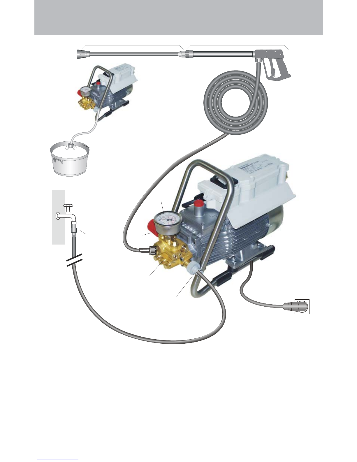
Connection principle
The KRÄNZLE HD7/120 + HD10/120 - high pressure cleaners are mobile machines. The design can be seen from the diagram.
Components
1 Water inlet connection with filter
2 Suction hose with filter (special
accessory) Order no. 15.038 3
3 High pressure pump
4 Press. gauge with glycerin filling
5 Unloader valve - safety valve
6 High pressure hose
7 Spray gun
8 Interchangeable lance with high
pressure nozzle
9 Nonreturn valve (see page 8)
Description
87
2
Water
6
4
5
3
1
230 V
9
Page 4

4
Water- and c leaning/detergent system
Water can be connected at mains pressure to the high pressure pump or it can
be sucked directly from a storage tank. The water is then forced under pressure
by the high pressure pump to the lance. The high pressure jet is formed by the
nozzle at the end of the lance.
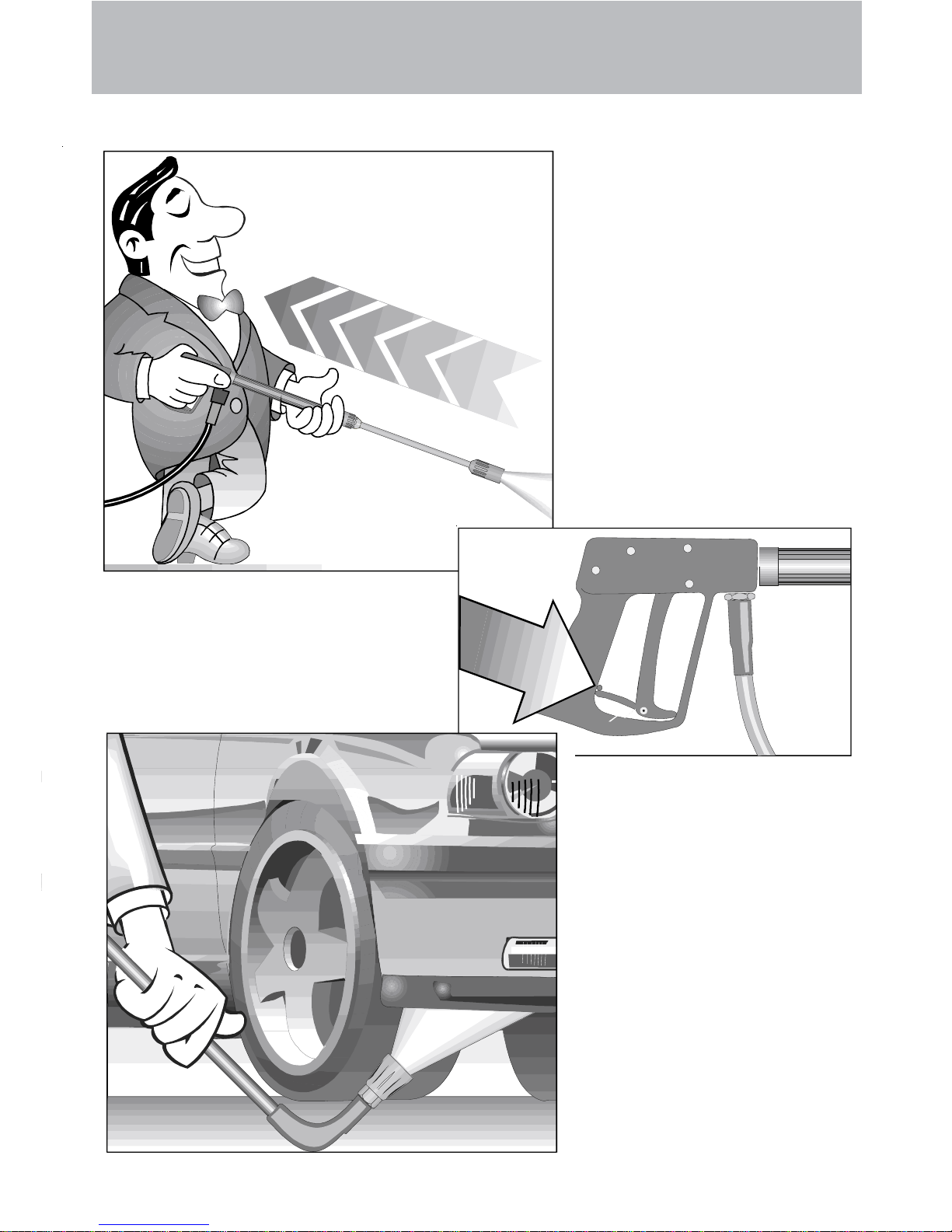
Lance with trigger gun
The machine can only be operated when the safety trigger is squeezed. The
machine can only be operated when the safety trigger is squeezed. When
the lever is squeezed, the spray gun opens. The liquid is then pumped to
the nozzle. The spray pressure increases and quickly reaches the selected
operating pressure.
When the trigger is released, the trigger gun closes and any further spraying
of liquid from the lance is stopped.
The increase in pressure when the trigger gun is closed causes the unloader
valve-safety valve to open. The pump remains switched on and continues to
pump liquid through the pump at reduced pressure. When the trigger gun is
opened, the unloader valve - safety valve closes and the pump ressumes
pressure spraying from the lance.
The trigger gun is a safety device. Repairs should
only be performed by qualified persons. Should
replacement parts be required, use only components
authorized by the manufacturer.
Unloader valve - safety valve
The unloader valve - safety valve protects the machine from a build p of
excess pressure, and is designed not to permit an excess pressure to be
selected for operation. The limit nut on the handle is sealed with a spray
coating.
*(see page 22:"Stopping leaks from the hose or gun".)
The operating pressure and spray rate can be steplessly adjusted by turning
the handle.
Replacements, repairs, new adjustments and sealing
should only be performed by qualified persons.
Description
Page 5
5
Description
The motor is protected from overload by a motor protection switch, which
automatically cuts out the motor in the event of overload. However should the
switch trip frequently, the cause of the malfunction should be located and
rectified (see page 6).
Motor protection switch
Setting up
Neither set up and operate the machine in rooms where there is
a risk of fire or explosion nor put it into puddles. Do not use the
machine under water.
Never use liquid containing solvents such as paint thinners,
petrol, oil or similar liquid matter. Pay attention to the
instructions of the manufacturers of the cleaning
agents. The seals in the machine are not resistant to solvents.
The spray of solvents is inflammable, explosive and poisonous.
CAUTION !
CAUTION !
When running your high pressure cleaner with hot water of 60°
C raised temperatures occur. Do not touch the machine
without safety gloves!
Replacements and inspection work should only be performed by
qualified persons when the machine is disconnected
from the power supply, i.e. pull out the plug from the
electrical socket.
Location
Page 6
6
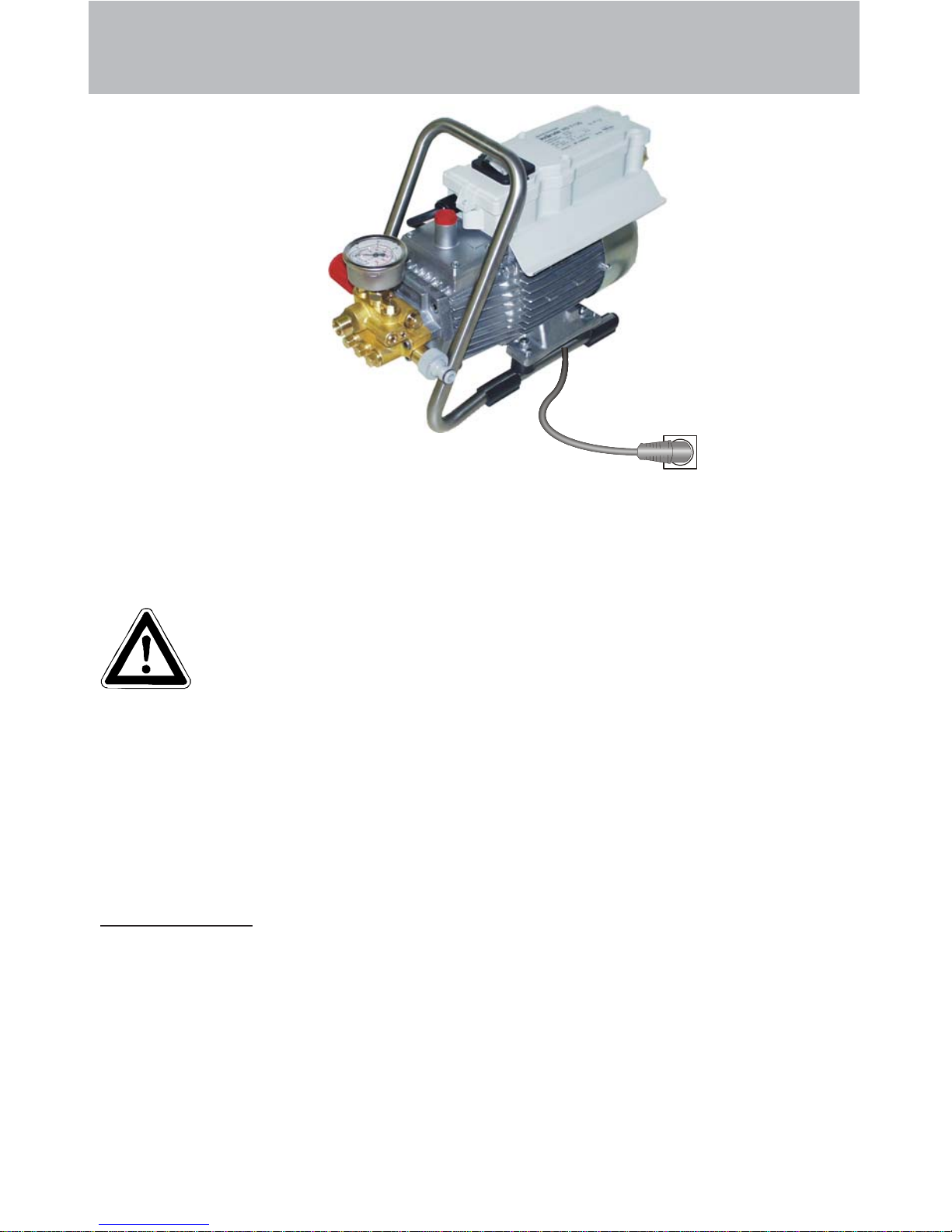
Electrical connection
The machine is supplied with an electrical power cable with plug.
The mains plug must be fitted to a standard grounded socket with a
30mA residual current operated device. The socket must be protected
with a 16A delay action fuse on the mains side.
KRÄNZLE HD 7/120 230 V olt / 50 Hz
KRÄNZLE HD 10/120 230 Volt / 50 Hz
When using an extension cable, this must have an earthed lead
which is properly connected to the socket. The conductors in the
extension cable must have a minimum cross section of 1.5 mm².
Plug connections must be of a spray-proof design, and may not
be located on a wet floor.
(with extension cables of more than 10 m - 2.5 mm
2
)
CAUTION !
The use of extension cables which are too long may lead to malfunctions and
start up difficulty.
When using a cable drum, always keep the cable wound as far as possible.
Description
230 V
Page 7
7
Description
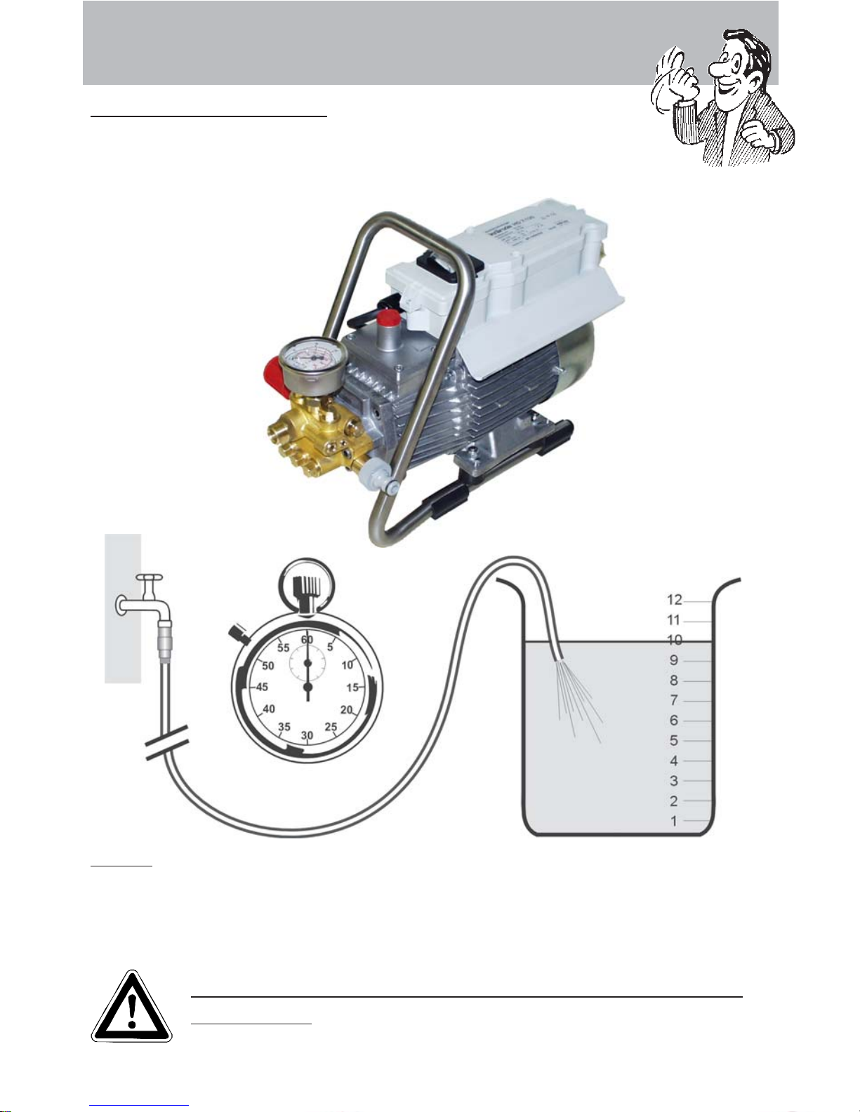
Please check that the high pressure cleaner has available the quantity
of water specified on page 2 (techn. specifications) (Litres per minute).
Water connection:
Test:
Allow the water to run through the supply hose into a bucket for 1 minute.
The received quantity of water must be at least the quantity given on page 2 !!!
Lack of water causes fast wear on seals (no
warranty)
Page 8

8
Brief operating instructions
When operating your high pressure cleaner
pay attention that it is in a horizontal position.
1. Connect the high pressure hose with the spray gun.
2. Connect to suitable water supply.
3. Flush the air from the pump (open and close the spray gun several
times)
4. Make the electrical connection
5. Switch on the machine with opened spray gun and commence
cleaning.
6. After completing the work, completely empty the pump (switch
the motor on for approximately 20 seconds without the suction and spray
gun).
- Only use clean water ! Protect from frost !
CAUTION !
Please pay attention to the regulations of your waterworks company. In accordance
with EN 61 770, the machine may not be directly connected to the public drinking
water supply lines.
A brief connection however is permissible according to DVGW (German Association
for Gas and Water Affairs) if a tube ventilator with check valve (Kränzle Order-No.
41.016 4) is built into the water supply.
Also indirect connection to the public drinking water supply lines is permissible by
way of free emission in accordance with EN 61 770; e.g. by using a reservoir with a
float valve.
Direct connection to a non-drinking water supply line is permissible.
High pressure hose and spray device
The high pressure hose and spraying device supplied with the machine are
made of high grade material, they are also optimized for the machine and
marked as required by the appropriate regulations.
- Hose length max. 20 m.
If replacement par ts are requir ed, only such parts
that are authorized by the manufacturer and which
bear the markings required by the appropriate regulations may be used. The high pressure hose and spray
device must be connected in a pressure-tight manner
(no leak). The high pressure hose may not be driven
over, pulled excessively, or twisted. The hose may
under no circumstances be pulled over sharp edges,
since otherwise the guarantee is automatically void.
Description
Page 9
9
Safety notes
As to the recoil see notice on page 2!
Always aim the
underbody lance. Note
when using an angled
underbody lance, like
for example lance no.
41.075 1, that there is a
certain amount of
torque in the recoil.
(Amount of torque 26
Nm)
Apply the safety catch on the
spray gun after each use, in
order to prevent uninten-
tional spraying!
Page 10
10
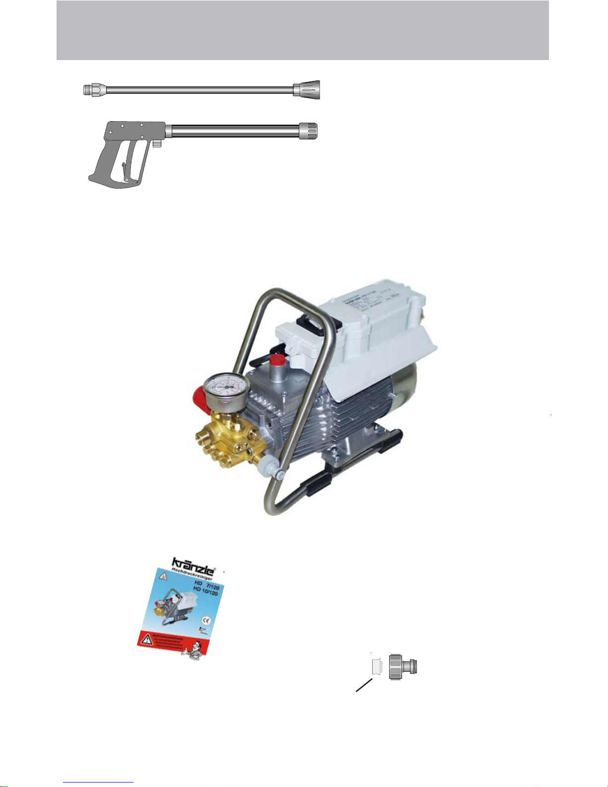
1. Spray lance with
high pressure nozzle
2. Spray gun with
insulated pistol grip
and screw connection
3. KRÄNZLE - High pressure cleaners HD7/120 / HD 10/120
4. Operating instructions
5. Water inlet components
T his is what you’ve purchased:
is already installed
Page 11
11
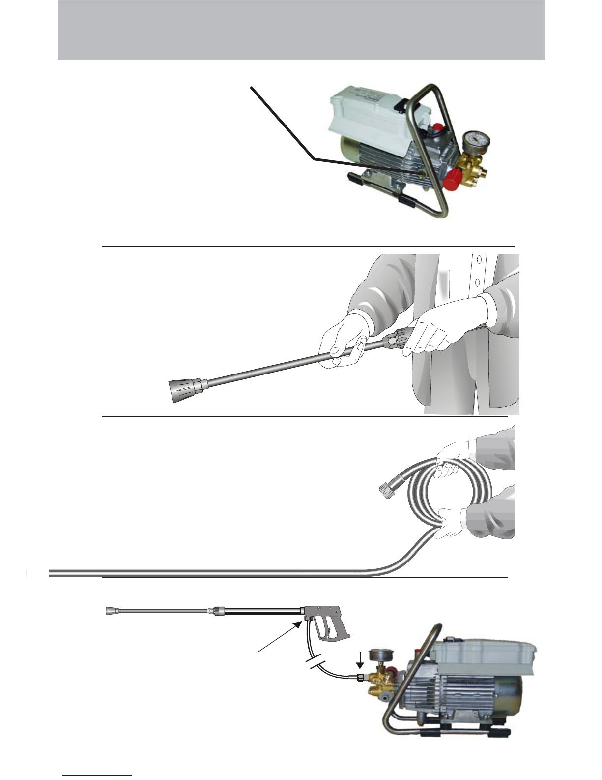
Pre paration for use
2. Connect the high pressure
lance to the spray gun.
High pressure hose
connected to machine
and spray gun.
1. Check oil level
Oil has to be visible in
the oil-level sight glass
3. Unroll hose without kinks and
connect with handgun and pump.
Max. extension 20 m-HP hose or 2 x
10 m with hose connections.
Page 12

4. The machine can be connected to
a pressurised water line with
60°C hot water (see page 2).
Ensure that the water supply is
clean when sucking from external
sources. The hose cross section
must be at least 1/2" = 12.7 mm (free
passage). Filter 1 must always be
clean.
Please make sure that
the filter is clean before using
your high pressure cleaner.
CAUTION !
When running your high pressure cleaner with hot water of
60° C raised temperatures occur.
Do not touch the pump without safety gloves!
Water
5. Maximum induction height 1.0 m
see technical
data on page 2
Pre paration for use
12
Page 13

13
This is accomplished by turning the
handwheel. The default setting is
maximum pressure.
Adjusting the pressure
Pre paration for use
1. Switch off the machine.
2. Cut off the water supply.
3. Open the spray gun briefly
until the pressure is released.
4. Apply the safety catch on the spray gun.
5. Remove the water hose and spray gun.
6. Drain the pump: switch on the motor for approx. 20 seconds.
7. Pull the plug from the socket.
8. Winter: store the pump in rooms above 0°C.
9. Clean the water filter.
To shut down the pump:
Page 14

14
Never direct the
water jet at the
machine itself !
Never direct the
water jet at a power
socket !
Never allow children
to use the high
pressure cleaner !
This is prohibited !
Page 15

15
Never direct the
water jet at people
or animals !
Do not damage the
power cable or repair it
incorrectly !
(Replace defective or
damaged cables
immediately !
Never work with a
defective appliance !)
Never pull the high
pressure hose if it has
formed kinks or
“nooses”!
Never pull the hose over
sharp edges !
This is prohibited !
Page 16

16
Sandblaster
Order No. 41.068 1
Flat brush
Order No. 41.073
Dirtkiller 03 (HD 7/120)
Order No. 41.073 8
Dirtkiller 045 (HD 10/120)
Order No. 41.072 5
Environmental, refuse disposal and water protection regulations must be observed when
using the accessories!
Additional KRÄNZLE-accessories for ...
Rotary scrubbing brush
Order No. 41.050 1
Drain and pipe cleaning hose
10 m - Order No. 41.058 1
15 m - Order No. 41.058
Underbody lance
Order No. 41.075
Page 17

17
... for fur ther combination possibilities
Car cleaning, glass, caravan, boat etc.
rotary washing brush with 40 cm extension and ST 30 nipple M 22 x 1.5
Underbody cleaning of cars, trailers and
equipment: lance 90 cm with high pressure
nozzle and ST 30 nipple M 22 x 1.5.
The lance must be aimed when spraying.
(See page 9)
Cleaning cars and all smooth surfaces:
brush with ST 30 nipple.
Rotary point sprayer for extreme soiling.
Dirtkiller with 40 cm extension and ST 30
nipple.
Cleaning pipes, channels and drains:
pipe cleaning hose with KN nozzle
and ST 30 nipple M 22 x 1.<<<<<5
Blasting old paint, rust and facades:
sand-blasting injector with suction lance,
3 m PVC hose and ST 30 nipple.
When sandblasting you must
wear protection clothes! Pay
attention to the instructions
of the manufacturer of the
abrasive!
<
Page 18

Small repairs -
18
Nozzle dirty or sticky!
Pressure gauge does not show full pressure.
Water comes out in spurts.
If you do not use the high-pressure cleaner
for some time the valves can stick
The high-pressure
hose vibrates.
Straighten a
paper clip...
When a valve is blocked,
the gauge
shows little
pressure or
no pressure
at all,
or the high
pressure
hose vibrates!
Open the valve
with a socket
wrench...
and remove the
valve screw, the
valve and the
o-ring.
Replace the rubber o-ring.
and remove the dirt
from the valve - the
valve inside must
be closed.
Retighten the
valve screw
...and repeat
on all 6
valves.
Now it works
as well as
before!
Page 19

19
The nozzle is blocked!
No water but the gauge shows full pressure !
- Do it yourself!
Rinse the hose through
first.
You should now have a
powerful stream of
water,
but if you
only get a few
drops from
the lance
remove the lance and clean
the nozzle.
Using the flat spray lance you
only have to clean the
front nozzle.
Straighten a paper
clip and clean the
nozzle.
Insert pointed object
into the hole and pull
the cap back!
Check visually whether the
nozzle is clean.
Now it works as well
as before.
Page 20

20
Small repairs - Do it yourself !
Stopping leaks from hose or gun
After closing the gun the manometer shows full pressure !
The pressure regulator switches on and off continuously!
If the
manometer
shows full
pressure,
Press the
trigger to
release the
pressure!!!
First
disconnect
the hose!
Then unscrew the
pump outlet with an
open-jew wrench.
Clean the return
element or replace
the O-Ring !
The pressure
regulator
switches on
and off from
pressure
loss!
Water can emerge at
these 3 points.
Check the seals and
replace the O-Ringe if necessary
or ave the gun checked by the dealer.
Replace the O-Ring
at the lance or at the
HP hose respectively!
Reconnect
the hose, gun
and lance!
Problem
solved already!
Pull out the
power plug!
Page 21

21
Gun with lance
No Description Qty. Ord.-No
Midi-gun with prolongation 12.160
Lance compl. with HP-nozzle 03 12.392 4
Lance compl. with HP-nozzle 045 12.392
6 Scheibe 5,3 DIN9021 1 50.152
7 Abzug-Hebel kpl. 1 12.144 1
15 Rohr kunststoffumspritzt 1 15.004 2
bds. R 1/4" AG
16 Überwurfmutter ST 30 M22 x 1,5 IG 1 13.276 1
17 Außen-Sechskant-Nippel R 1/4" IG 1 13.277 1
18 O-Ring 9,3 x 2,4 1 13.273
28 Aluminium-Dichtring 6 13.275
51 Düsenschutz M12x1 1 26.002 1
52 Rohr 400 mm; bds. M12x1 1 15.002
53 ST 30 Nippel M 22 x 1,5 / R1/4" m. ISK 1 13.363
54 Flachstrahldüse 028 (bei HD 7/120) 1 M20028
54.1 Flachstrahldüse 042 (bei HD 10/120) 1 M20042
A
Rep.-Kit 12.158
Pos: 3, 4, 5, 8, 9, 12, 15, 16; 21
B Griff komplett 12.164
Page 22

22
Complete assembly
Page 23

23
HD 7/120 / HD 10/120
No Description Qty. Ord.-No
Spare parts list KRÄNZLE
HD 7/120 / HD 10/120
Complete assembly
2 Tragbügel 1 44.581
3 Gummiprofilfuß 4 44.582
4 Senkschraube M6x20 1 43.473 1
5 Gummipuffer 30 x 20 4 46.023 1
6 Scheibe 8,4 4 41.409
7 Mutter DIN985 M8 4 41.410
8 Midi-Pistole mit Verlängerung 1 12.160
9 Lanze mit Flachstrahldüse 028 (HD 7/120) 1 12.392 5-M20028
9.1 Lanze mit Flachstrahldüse 042 (HD 10/120) 1 12.392 5-M20042
10 Schmutzkiller 03 kpl. mit Lanze (HD 7/120) 41.073 8
10.1 Schmutzkiller 045 kpl. mit Lanze (HD 10/120) 41.072 5
19 O-Ring 9,3 x 2,4 2 13.273
20 HD-Schlauch NW 6 10 m 210 bar 1 43.416
Page 24

24
Motor
Page 25

25
No Description Qty. Ord.-No
KRÄNZLE HD 7/120 / HD 10/120
Spare parts list KRÄNZLE
HD 7/120 / HD 10/120
Motor
1 Ölgehäuse
mit Dichtung und Deckel 1 44.501
2 Stator (HD 7/120) 1 23.001 2
2.1 Stator (HD 10/120) 1 23.002 4
3 Motorwelle mit Rotor (HD 7/120) 1 43.104
3.1 Motorwelle mit Rotor (HD 10/120) 1 43.024
4 Passfeder 6 x 6 x 20 1 41.483 1
5 Motor-Lager B-Seite Z-Lager 1 43.025
6 Motor-Lager A-Seite Schulterl. 1 43.026
7 Schelle für Lüfterrad 1 44.534 1
8 Öldichtung 25 x 35 x 7 1 41.024
9 Lüfterrad 1 44.534
10 Lüfterhaube 1 41.497
11 Flachdichtung 1 44.513
12 Lüsterklemme 3-pol. 1 43.031 2
13 Schaltkasten 1 44.508 1
14 Schalter 8,5 A (HD 7/120) 1 43.329
14.1 Schalter 12 A (HD 10/120) 1 43.033
15 Klemmrahmen mit 1 43.453
Schalterabdichtung
16 Kabelverschraubung PG 11 mit Knicks. 1 41.091
17 Gegenmutter PG 11 1 44.521
18 Kondensator 40 µF 1 43.035
19 Netzkabel für 230V / 50/60Hz 1 41.092
20 Blechschraube 3,5 x 9,5 2 41.088
21 Blechschraube 2,9 x 16 1 43.036
22 Innensechskantschr. M 5 x 12 4 40.134
23 Innensechskantschr. M 5 x 30 4 42.130
24 Erdungsschraube kpl. 1 43.038
25 Deckel für Schaltkasten 1 44.512
26 Dichtung für Deckel 1 44.522
27 Kunststoffschraube 5,0 x 25 4 41.414
28 Blechschraube 3,9 x 9,5 3 41.636
29 Toleranzhülse 1 43.063 1
Page 26

26
Transmission
Page 27

27
KRÄNZLE HD 7/120 / HD 10/120
No Description Qty. Ord.-No
1 Gehäuseplatte 1 43.003
2 Öldichtung 14 x 24 x 7 3 41.631
3 O-Ring 83 x 2 1 43.039
4 Plungerfeder 3 43.040
5 Federdruckscheibe 14 mm 3 43.041
6 Plunger 14 mm 3 43.005
7 Sprengring 14 mm 3 41.635
8.1 Swash plate 12,5° (HD 7/120) 1 41.028-12,5
8.2 Swash plate 9,5° (HD 10/120) 1 41.028-9,5
please specify swash plate angle
10 Axial-Rillenkugellager 3-teilig 1 43.486
12 Innensechskantschraube M 8 x 25 4 40.053
13 Verschlußschraube M 18 x 1,5 1 41.011
14 O-Ring 12 x 2 3 15.005 1
15 Ölschauglas 1 42.018 1
16 Ölverschlußschraube rot 1 43.437
17 Dichtung Öldeckel 1 44.501 1
18 Deckel Ölgehäuse 1 44.501 2
19 Innensechskantschraube M 5 x 12 4 41.019 4
Spare parts list KRÄNZLE
HD 7/120 / HD 10/120
Transmission
Page 28

28
Valve housing
Page 29

29
KRÄNZLE HD 7/120 / HD 10/120
Spare parts list KRÄNZLE
HD 7/120 / HD 10/120
Valve housing
No Description Qty. Ord.-No
No Description Qty. Ord.-No
1 Ventilgehäuse 1 44.523
2 Ventilstopfen 5 41.011
3 Ventilstopfen mit R1/4" IG 1 41.011 1
4 Ventile (rot) 6 41.612
5 Dichtstopfen M 8 x 1 1 13.158
6 Dichtstopfen M 10 x 1 1 43.043
7 O-Ring 12 x 2 15 15.005 1
8 O-Ring 11 x 1,5 2 12.256
9 Edelstahlsitz 2 14.118
10 Sicherungsring 2 13.147
11 Edelstahlkugel 8,5 mm 1 13.148
11.1 Edelstahlkugel 10,0 mm 1 12.122
12 Edelstahlfeder 1 14.119
13 Verschlussschraube 1 14.113
14 Steuerkolben 6 mm für AZ 1 43.044
15 Parbaks für Kolben 14 mm 1 14.123 1
16 Parbaks für Spindel 6 mm 1 14.123 2
17 MS-Scheibe 1 43.045
18 Kolbenführung 6 mm 1 14.130 1
19 Mutter M 6 2 14.127 1
20 Feder schwarz für AZ-Pumpe 1 43.046
21 Federdruckscheibe 1 43.047
22 Kugellager 1 43.048
23 Handrad M 6 für AZ-Pumpe 1 43.049
24 Mutter M 6 mit SW 8 1 43.010
25 Kappe für Handrad AZ-Pumpe 1 43.050
26 Manometer 1 15.039
27 Stützring 3 43.091
28 Gewebemanschette 14x24x5 3 41.613 1
29 Backring 14 x 24 3 41.614
30 O-Ring 26 x 2 3 43.052
31 Leckagering 3 43.053
32 Manschette 14 x 20 x 4/2 3 43.054
33 Zwischenring mit Abstützung 3 43.055
34 Rückschlagfeder 1 14.120 1
35 Ausgangsteil für Kugelrückschlagv. 1 44.583
36 Verschlusstopfen bei quadro TS 1 13.181
37 Aluminium-Dichtring bei quadro TS 2 13.275
42 Innensechskantschr. M 8 x 25 2 40.053
43 Innensechskantschr. M 8 x 40 2 43.059
44 Dichtring Kupfer 1 14.149
45 Sauganschluss 1 41.016
46 Wasserfilter 1 41.046 1
48 Gummi Dichtring 1 41.047 1
49 Steckkupplung 1 41.047 2
50 O-Ring 1 41.047 3
52 O-Ring 18 x 2 1 43.446
Rep.-kit valves 41.648
6x Pos. 4, 12x Pos. 7
Rep.-kit sleeves 43.060
3x Pos. 28; 3x Pos. 29; 3x Pos. 30, 3x Pos. 32
Valve housing compl. 44.584
Pos. 1-25; Pos. 27-43
Guide piston with seals 44.532
Pos. 14; Pos. 15
Guide piston with handwheel 44.532 1
Pos. 7; Pos. 14-25
Page 30

30
Dirtkiller (special accessory)
No Description Qty. Ord.-No
1 Sprühkörper 1 41.520
2 O-Ring 6,88 x 1,68 1 41.521
3 Düsensitz 1 41.522
4 Düse 03 (HD 7/120) 1 41.523 4
4.1 Düse 045 (HD 10/120) 1 41.523
5 Stabilisator 1 41.524
6 O-Ring 1 40.016 1
7 Sprühstopfen 1 41.526
8 Rohr 400 mm 2x M 12 x 1 1 41.527
9 ST 30-Nippel M 22 x 1,5 / M 12 x 1 ISK 1 13.363
11 Front cap for Dirtkiller 1 41.528 1
12 Rear cap for Dirtkiller 03 (HD 7/120) 1 41.542 1
12.1 Rear cap for Dirtkiller 045 (HD 10/120) 1 41.540 2
Rep.-kit Dirtkiller 03 41.096 1
consisting of: 1x 2; 3; 4; 5
Rep.-kit Dirtkiller045 41.097
consisting of: 1x 2; 3; 4; 5
Dirtkiller 03 compl. with lance 41.073 8
Dirtkiller 045 compl. with lance 41.072 5
Spare parts list Dirtkiller
Page 31

31
Terminal strip
Weber-Unimat WT 22 - 551
8,5A excess current release (HD 7/120)
12A excess current release (HD 10/120)
Motor-Stator
Wiring diagram for KRÄNZLE HD 7/120 / HD
10/120
Wiring dia gram / Warranty
C : 40 µF
braun = brown
blau = blue
schw = black
rt = red
ge = yellow
gn = green
ws = white
Warranty
This warranty covers material and/or workmanship related defects only and does not
extend to ordinary wear.
Machine must be operated according to enclosed operating instructions which are part of
present warranty conditions.
A
ll products sold directly to private customers are warrantied for a period of 24 months,
whereas the warranty period for industrial purchases is limited to 12 months.
In case of any warranty claims, please have your HP cleaner together with accessories
and your purchase document ready and contact your nearest dealer or authorized service
point which can also be looked up in the internet at www.kraenzle.com
.
Warranty is void in case of attempts to modify any of the safety devices or in the event of
exceeding temperature or rpm limits - this also applies to undervoltage, low water and/or
polluted water. Gauge, nozzle, valves, sealing gaskets, high pressure hose and spray
equipment are considered wear parts and do not fall under this warranty.
Page 32

32
Inspections
The machine must be inspected according to the “Guidelines for Liquid Spray
Devices” at least once every 12 months by a qualified person, to ensure that continued safe operation is guarateed. The results of the inspection are to be recorded in
writing. This may be done in any form.
Accident prevention
The machine is designed for accidents to be impossible if used correctly.
The operator is to be notified of the risk of injury from hot machine parts and the
high pressure water jet. The “Guidelines for Liquid Spray Devices” must be complied
with. (see page 14 and 15)
Oil change:
Check the oil level at the oil sight glass prior to each use.
(Ensure horizontal position!) The oil level should be at the middle of
the sight glass. With high atmospheric humidity and temperature
fluctuation there may be condensation (oil has a greyish colour);
Then the oil must be changed.
First oil change after approx 50 hours of operation. Thereafter, no more oil change is
required for the lifetime of the equipment. If it becomes necessary during repairs, or
because the oil has a greyish colour to perform an oil change, then the oil sight
glass should be opened and the oil emptied into a container. The oil must be caught
in a container and disposed of in a responsible, legal manner.
New oil: 0.25 l - Motor oil: W 15/40
Oil leak
In the event of an oil leak contact customer service (dealer) immediately. (damage to
environment or transmission)
General rules
Page 33

I. Kränzle GmbH
Elpke 97
33605 Bielefeld
High-pressure-cleaners
Hochdruckreiniger
Nettoyeurs À Haute Pression
R
33
(Managing Director)
EC declaration of conformity
Bielefeld, 11.02.05
We hereby declare,
that the high-pressure models:
(techn. documentation available from):
comply with the following guidelines
and specifications and their
amendments for high-pressure
cleaners:
Sound power level measured:
guaranteed:
Applied specifications and
standards:
Kränzle HD 7/120
Kränzle HD 10/120
Manfred Bauer, Fa. Josef Kränzle
Rudolf-Diesel-Str . 20, 89257 Illertissen
Machine guideline 89/392/EEC
Low voltage guideline 73/23 EEC
Specification for electromagnetic
compatibility 89/336 EEC
Outdoor noise directive 2000/14/EC,
Art. 13, High-pressure water jet machines
Appendix 3, part B, chapter 27
HD 7/120: 81 dB (A); HD 10/120: 89 dB (A)
HD 7/120: 84 dB (A); HD 10/120: 91 dB (A)
EN 60 335-2-79:2004
EN 55 014-1 / A2:2002
EN 55 014-2 / A1:2001
EN 61 000-3-2 / A14:2000
EN 61 000-3-3 / A1:2001
Page 34

34
Notes
Page 35

35
Notes
Page 36

Reprint only allowed with the authorization of
As date of 06.07.2005
Order n°: 30.760 1
R
 Loading...