

Page 1

GB
Operating manual
High-pressure cleaners
Read and conform safety instructions before use!
Keep instructions in a safe place for later use and
pass them on to any future user.
Page 2
2
10 - 250 bar
270 bar
16 l/min
70 °C
2,5 m
20 m
GX 390 LX2
83 kg
103 dB (A)
appr. 42 Nm
36 Nm
41 193 1*
Dear customer
We would like to congratulate you on your new mobile high pressure cleaner and
to thank you for the purchase.
To ease your introduction to the use of the cleaner, we have provided the following
pages of explanations, tips and hints, which we ask you to read before using for
the rst time.
The equipment will assist you professionally in all cleaning tasks, e.g.:
- facades
- agstones
- terraces
- vehicles of all types
- sheds
- machines etc.
Description
- barrels and containers
- channels
- Streets etc.
Operating pressure,
steplessly adjustable
Perm. overpressure
Water output
at 1800 rpm
Hot water input
Suction height
High pressure
hose
with hose drum
Combustion motor
Honda
Weight
Sound level Gua-
ranteed sound level L
WA
Recoil at lance
Torque
Order n°:
Technical
data
B 240 T
B 200 TB 170 T
10 - 150 bar
165 bar
13 l/min
70 °C
2,5 m
20 m
GX 160 LX2
58 kg
103 dB (A)
appr. 32 Nm
29 Nm
41 190 1
10 - 165 bar
180 bar
12 l/min
70 °C
2,5 m
20 m
GX 200 LX2
58 kg
103 dB (A)
appr. 27 Nm
24,3 Nm
41 191 1
10 - 220 bar
240 bar
16 l/min
70 °C
2,5 m
20 m
GX 340 LX2
83kg
103 dB (A)
appr. 38 Nm
33 Nm
41 192 1*
Permissible tolerance for gures ± 5 % in acc. with VDMA uniform sheet 24411
with speed control *
B 270 T
(Assumed length of lance: 0,9 m)
10 - 200 bar
230 bar
20 l/min
50 °C
2,5 m
20 m
GX 390 LX2
83 kg
103 dB (A)
appr. 42 Nm
36 Nm
41 194 1*
B 230 T
Spec. appliance
*1
*1
Minimum quantity of water to be led to the equipment!
Page 3
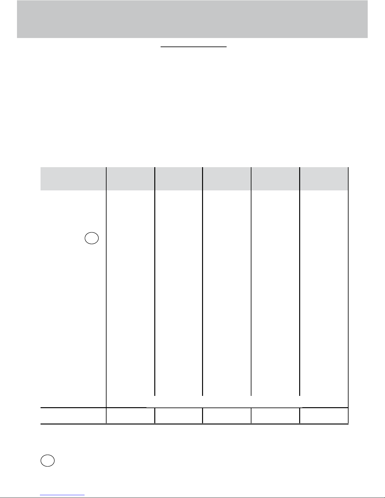
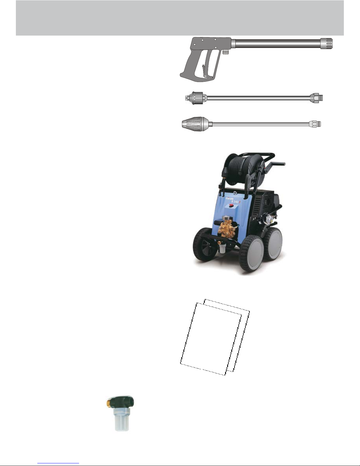
3
Water
7
8
5 Unloader valve - safety valve
6 High pressure hose
7 Spray gun
8 Interchangeable lance with high
pressure nozzle
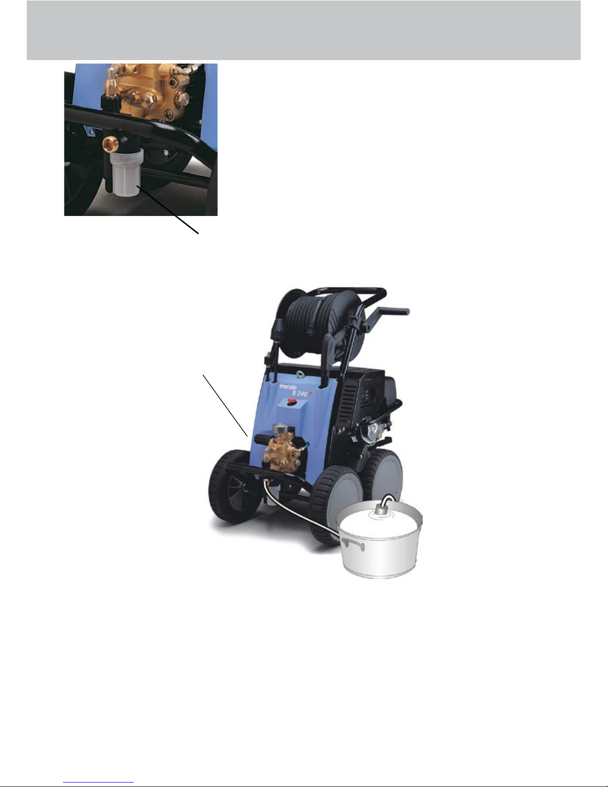
1 Water inlet connection with lter
2 Suction hose with lter (special
accessory) Order no. 15.038 3
3 High pressure pump
4 Press. gauge with glycerin lling
The KRÄNZLE B170 T + B200 T + B230 T+ B240 T + B270 T - high pressure
cleaners are mobile machines. The design can be seen from the diagram.
Construction
Item
Description
1
2
5
6
Page 4

4
Description
Water and Cleaning / Pegemittel System
Water can be connected at mains pressure to the high pressure pump or it can
be sucked directly from a storage tank. The water is then forced under pressu
-
re by the high pressure pump to the lance. The high pressure jet is formed by
the nozzle at the end of the lance.
Detergent and caring agents can be added through a high pressure injector
(special accessory). Up to max 20m HP hose length.
The rules concerning the environment, refuse and ground water
protection must be complied with!
(Information to be obtained from environmental dept, town
works, etc.)
Lance with trigger gun
The machine can only be operated when the safety trigger is squeezed. The
machine can only be operated when the safety trigger is squeezed.
When the lever is squeezed, the spray gun opens. The liquid is then pumped
to the nozzle. The spray pressure increases and quickly reaches the selected
operating pressure.
When the trigger is released, the trigger gun closes and any further spraying of
liquid from the lance is stopped.
The increase in pressure when the trigger gun is closed causes the unloader
valve-safety valve to open. The pump remains switched on and continues to
pump liquid through the pump at reduced pressure. When the trigger gun is
opened, the unloader valve - safety valve closes and the pump ressumes pres
-
sure spraying from the lance
The trigger gun is a safety device. Repairs should only be performed by qua
-
lied persons. Should replacement parts be required, use only
components authorized by the manufacturer.
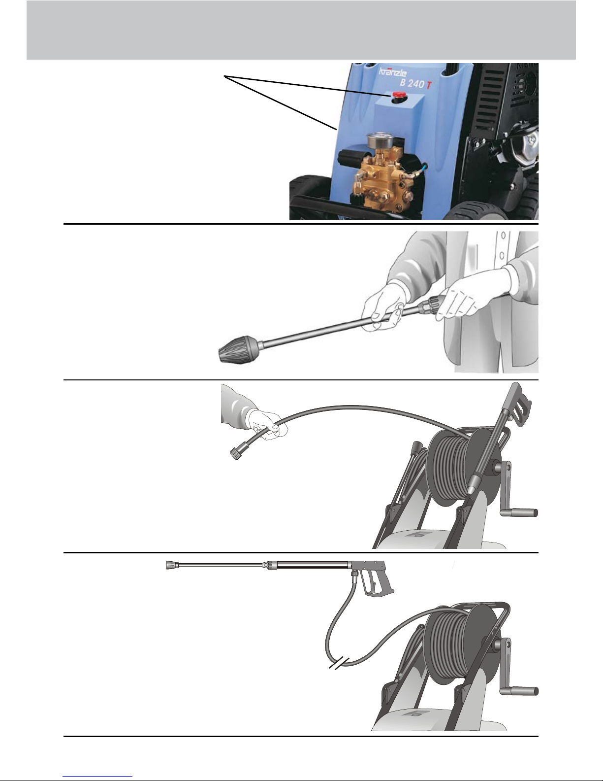
Unloader valve - safety valve
The unloader valve - safety valve protects the machine from a
build p of excess pressure, and is designed not to permit an excess pressure
to be selected for operation. The limit nut on the handle is sealed with a spray
coating.
The operating pressure and spray rate can be steplessly adjusted by turning
the handle.
Replacements, repairs, new adjustments and sealing should only be performed
by qualied persons.
Page 5
5
Description
For the motor follow the Honda operating manual
only.
Motor-safety: (see Honda operating manual)
Honda motors are safe and reliable if they are operated correctly. Read the operating manual carefully before using the motor and try to understand the contents of
the manual completely.
Not following this advice could lead to injuries or damage of the equipment.
To avoid a possible re hazard and to ensure the necessary ventilation
the motor has to be operated at a distance of at least 1 m from buil-
dings and objects. Inammable objects have to be kept away from the
surrounding area of the motor.
Children and pets have to be kept away from the motor, as there is
a danger of suffering burns from hot motor parts and to be injured by
equipment driven by the motor.
Get to know the motor and especially learn how to switch it off quickly.
Do not allow persons to operate the motor who are not familiar with it.
When running your high pressure cleaner with hot water of 70° C (with
B230 T 50°) raised temperatures occur.
Do not touch the machine without safety gloves.
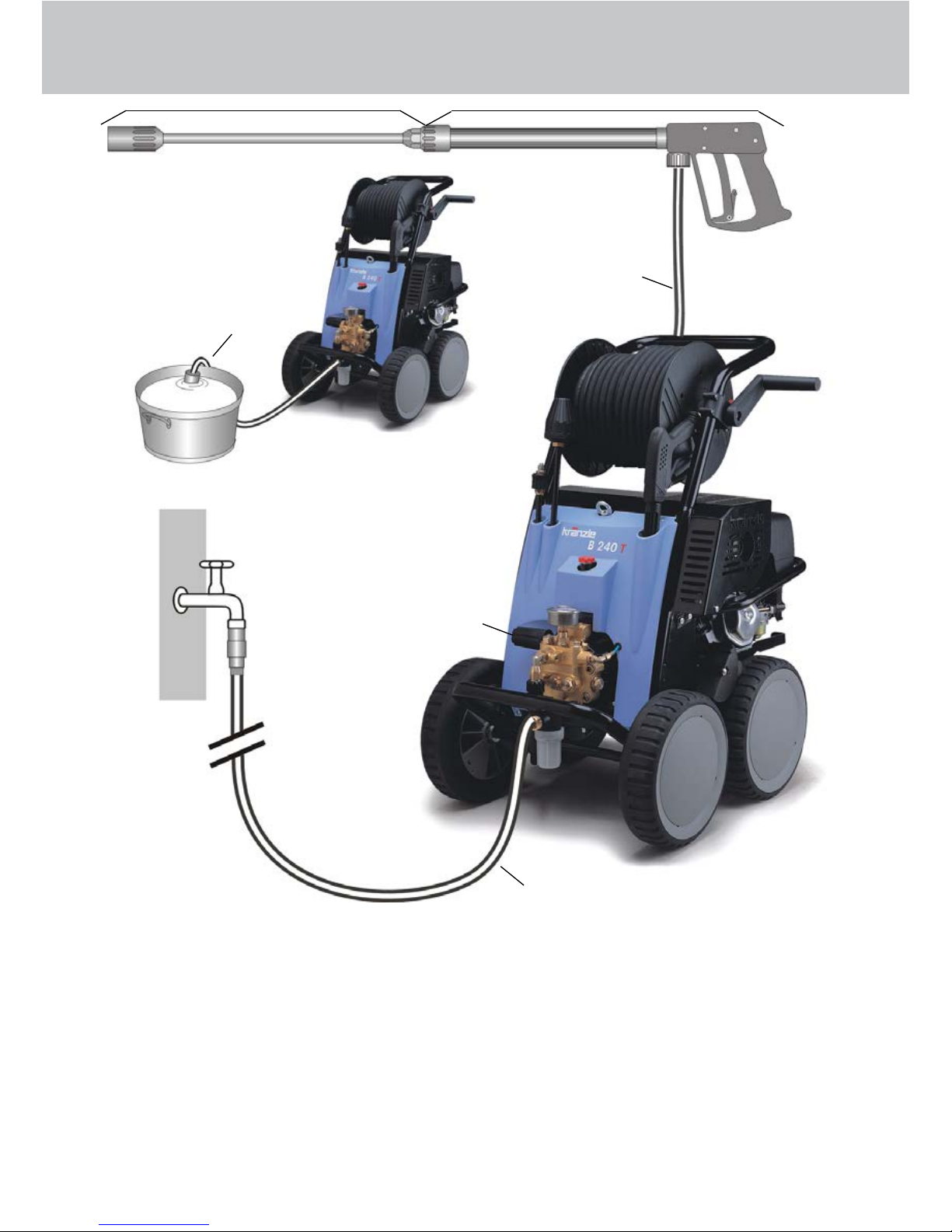
CAUTION !
Never use liquid containing solvents such as paint thinners, petrol, oil or similar li-
quid matter. Pay attention to the instructions of the manufacturers of the
cleaning agents. The seals in the machine are not resistant to solvents.
The spray of solvents is inammable, explosive and poisonous.
Neither set up and operate the machine in rooms where there is a risk
of re or explosion nor put it into puddles. Do not use the machine
under water.
Do NOT !! tilt or turn round the high-pressure cleaner during transport
or operation for longer than 1 minute!
CAUTION !
Setting up: Location
Page 6

6
Description
Please check that the high pressure cleaner has available the quantity of water
specied on page 2 (techn. specs.) (Litres per minute).
Water connection:
Test:
Allow the water supply hose to run for 1 minute into a bucket.
The received quantity of water must be at least the quantity given on page 2 !!!
Lack of water causes fast wear on seals (no warranty)
Brake
The high-pressure cleaner is tted with a brake that prevents the machine from
rolling away on uneven ground.
Always apply the brakes rmly when working with the machine !!!
Page 7

7
Description
Brief operating instructions
1. Connect the high pressure hose with spray gun
and machine.
2. Connect the suitable water supply.
3. Flush the air from the pump (open and close the spray gun
several times).
4. Switch on the motor while the spray gun is open and
commence cleaning.
5. After completing the work, completely empty the pump
(switch the motor on for approximately 20 seconds without the suction
and pressure hose).
- Only use clean water ! Protect from frost !
- Do NOT !! tilt or turn round the high-pressure cleaner during
transport
CAUTION !
Please pay attention to the regulations of your waterworks company.
In accordance with EN 61 770, the machine may not be directly connected to the
public drinking water supply lines.
A brief connection however ist permissible according to DVGW (German Asso-
ciation for Gas and Water Affairs) if a tube ventilator with check valve (KRÄNZLE
Order-No. 41.016 4) is built into the water supply.
Also indirect connection to the public drinking water supply lines is permissible by
way of free emission in accordance with EN 61 770; e.g. by using a reservoir with
a oat valve.
Direct connection to a non-drinking water supply line is permissible.
High pressure hose and spray device
The high pressure hose and spray device supplied with the machine are made
of high grade material, they are also optimized for the machine and marked as
required by the appropriate regulations.
If replacement parts are required, only such parts that are authorized
by the manufacturer and which bear the markings required by the appropriate regulations may be used. The high pressure hose and spray
device must be connected in a pressure-tight manner. The high pressure hose may not be driven over, pulled excessively, or twisted. The
hose may under no circumstances be pulled over sharp edges, since
otherwise the guarantee is automatically void.
Page 8
8
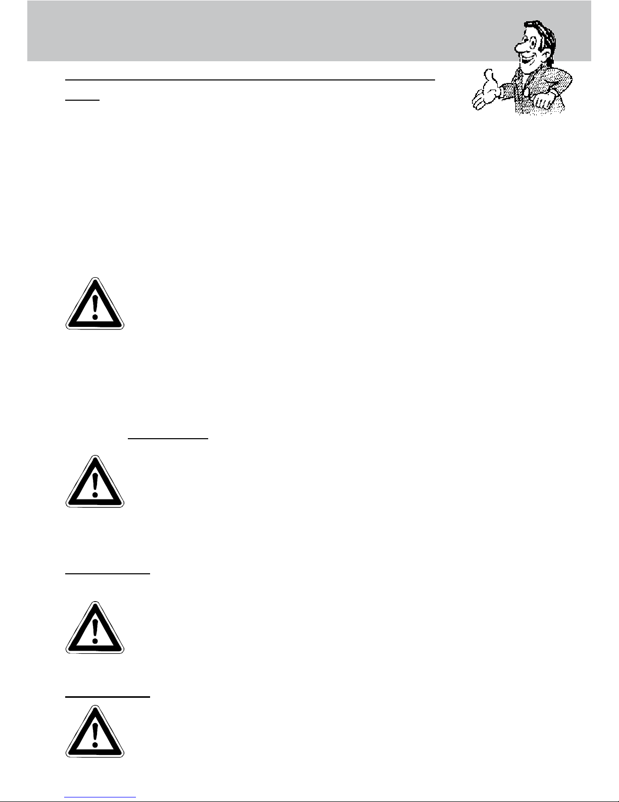
As to the recoil
- see notice on
page 2!
Always aim the underbody
lance. Note when using an
angled underbody lance,
like for example lance No.
41075, that there is a certain amount of torque in the
recoil.
(See also notice on page 2)
Apply the safety catch on the spray
gun after each use, in order to pre-
vent unintentional spraying!
Safety notes
Page 9
9
2. Spray lance with high pressure
nozzle, at spray
4. KRÄNZLE - high-pressure cleaners
B 170 T
B 200 T
B 240 T
B 270 T
B 230 T
incl. hose drum with 20 m HP-hose
6. Water lter
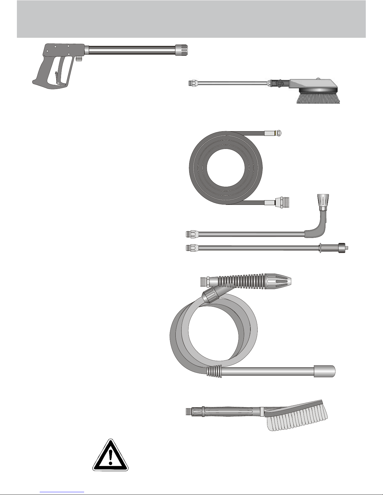
This is what you’ve purchased:
1. Spray gun with insulated
pistol grip and screw connection
3. Turbokiller
5. Operation manual pump
Operation manual motor
Page 10
10
1. Check oil level
( Pump and motor)
Preparation for use
3. Unroll hose without kinks and connect with handgun and pump. Use
HP hose of max. 20 m length.
High pressure hose connected
to machine and spray gun.
2. Connect high pressure lance or
Turbokiller to the spray gun.
Page 11
11
Water
5. Maximum induction
height 2.5 m - see technical data
on page 2.
Please make sure that the lter is
clean before using your high pressure
cleaner.
4. The machine can be connected
to a pressurised water line with cold
or up to 70 °C hot water (see page 2).
Ensure that the water supply ist clean
when sucking from external sources.
The hose cross section must be
at least 1/2“ = 12.7 mm (free
passage). Filter must
always be clean.
Preparation for use
Adjusting the pressure
This is accomplished by
turning the handwheel.
The default setting is
maximum pressure.
1. Switch off the machine
2. Cut off the water supply
3. Open the spray gun briey until the pressure is released
4. Apply the safety catch on the spray gun
5. Remove the water hose and high pressure hose
6. Drain the pump: switch on the motor for approx. 20 seconds
7. Winter: store the pump in rooms above 0° C
8. Clean the water lter
To shut down the pump:
Page 12

12
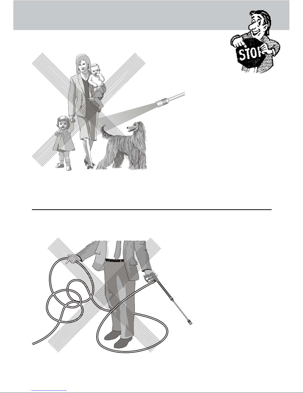
This is prohibited !
Never allow children to
use the high pressure
cleaner !
Never direct the water jet at the machi-
ne itself !
Page 13
13
Never direct the water
jet at people or animals
!
Never pull the high pres-
sure hose if it has for-
med kinks or “nooses”!
Never pull the hose
over sharp edges !
This is prohibited !
Page 14
14
Additional KRÄNZLE-accessories for ...
Environmental, refuse disposal and water protection regu-
lations must be observed when using the accessories!
Rotary scrubbing brush
Order No. 41.050 1
Sandblaster
Order No. 41.068 1
Underbody lance
Order No. 41.075
Flat brush
Order No.41.073
Drain and pipe cleaning hose
8 m - Order No. 41.051
15 m - Order No. 41.058
Page 15

15
Car cleaning, glass, caravan, boat etc.
rotary washing brush with 40 cm exten-
sion and ST 30 nipple M 22 x 1,5
Cleaning cars and all smooth surfaces :
brush with ST 30 nipple M 22 x 1,5.
Underbody cleaning of cars, trailers and
equipment: lance 90 cm with high pressure
nozzle and ST 30 nipple M 22 x 1,5.
The lance must be aimed when spraying.
Cleaning pipes, channels and drains:
pipe cleaning hose with KN nozzle
and ST 30 nipple M 22 x 1,5
When sandblasting you must wear
protection clothes! Pay attention to the
instructions of the manufacturer of the
abrasive!
Blasting old paint, rust and facades: sand-
blasting injector with suction lance, 3 m PVC
hose and ST 30 nipple.
... further combination possibilities
Rotary point sprayer for extreme soiling.
Dirtkiller with 40 cm extension and ST 30
nipple M 22 x 1,5.
Page 16

16
Small repairs -
Nozzle dirty or sticky!
Pressure gauge does not show full pressure.
Water comes out in spurts.
If you do not use the high-pressure cleaner
for some time the valves can stick
The high-pressure
hose vibrates.
Straighten a
paper clip...
When a valve is blocked,
the gauge
shows little
pressure or
no pressu-
re at all,
or the high
pressure
hose vibra-
tes!
Open the valve
with a socket
wrench...
and remove the
valve screw, the
valve and the
o-ring.
Replace the rubber o-ring.
and remove the
dirt from the valve
- the valve inside
must be closed.
Retighten the
valve screw
...and repeat
on all 6
valves.
Now it works
as well as
before!
Page 17

17
The nozzle is blocked!
No water but the gauge shows full pressure !
Rinse the hose through
rst.
You should now have a
powerful stream
of
water,
but if you
only get a few
drops from
the lance
remove the lance and clean
the nozzle.
Using the at spray lance you
only have to clean the front
nozzle.
Straighten a paper
clip and clean the
nozzle.
Insert pointed object
into the hole and pull
the cap back!
Check visually whether the
nozzle is clean.
Now it works as well
as before.
- Do it yourself!
Page 18

18
Small repairs - Do it yourself!
Stopping leaks from hose or gun
After closing the gun the manometer shows full pressure !
The pressure regulator switches on and off continuously!
Press the trigger
to release the
pressure!!!
If the
manometer
shows full
pressure,
First dis-
connect the
hose!
Then unscrew
the pump outlet
with an open-jew
wrench.
Clean the return
element or replace
the O-Ring !
The pressure
regulator
switches on
and off from
pressure
loss!
Water can emerge at
these 3 points.
Check the seals and
replace the O-Ringe if necessary
or ave the gun checked by the dealer.
Replace the O-Ring
at the lance or at the
HP hose respectively!
Reconnect
the hose, gun
and lance!
Problem
solved already!
Page 19

19
General rules
The machine must be inspected according to the „Guidelines for Liquid Spray Devices“ at least once every 12 months by a qualied person, to ensure that continued safe operation is guaranteed. The results of the inspection are to be recorded
in writing. This may be done in any form.
Inspections:
The machine is designed for accidents to be impossible if used correctly. The
operator is to be notied of the risk of injury from hot machine parts and the high
pressure water jet. The „Guidelines for Liquid Spray Devices“ must be complied
with. (see page 12 and 13)
Accident prevention
Check the oil level at the oil sight glass prior to each use.
(Ensure horizontal position!) The oil level should be at the middle of the sight
glass. With high atmospheric humidity and temperature uctuation there may be
condensation (oil has a greyish colour); Then the oil must be changed.
Oil change for high-pressure pump B170 T / B200 T
First oil change after approx 50 hours of operation. Thereafter, no more oil change
is required for the lifetime of the equipment. If it becomes necessary during repairs
to perform an oil change, then the oil sight glass should be opened and the oil
emptied into a container. The oil must be caught in a container and disposed of in
a responsible, legal manner.
New oil: 0,3 l - Motor oil W 15/40
Oil change for high-pressure pump B230 T / B240 T / B270 T
The oil of your high pressure pump should be changed after approx. 40 hours of
operation, or no later than when it takes an a grey or whitish colour. Open the oilplug over a container and drain off all the oil. The oil must be caught in a contianer
and disposed of in a responsible, legal manner.
New oil: 1,0 l - Castrol Formula RS
Oil leak
In the event of an oil leak contact customer service (dealer) immediately. (damage
to environment or transmission)
Page 20

20
Complete assembly
Page 21

21
Kränzle B170 T / B200 T
No Description Qty. Ord.-No
1 Motor Honda GX 160 LX2 für B170 T 1 24 027
Motor Honda GX 200 LX2 für B200 T 1 24 027 2
2 Wagen 1 40 230
3 Schubbügel 1 40 245
4 Bremshebel 1 40.246
6 Frontplatte B170 T 1 40 231 1
Frontplatte B200 T 1 40 231 2
7 Blechschraube 4,8 x 12 4 44 112
8 Köcher groß 1 40 232
9 Kunststoffschraube 5 x 14 7 43 426
10 Köcher klein 1 40 233
11 Rad 4 44.017
12 Achsklemmring 20 mm 4 40.142
13 Radkappe 4 44.018
14 Stift 6 x 40 1 44.035 1
15 Saugschlauch 3 m mit Sauglter 1 15.038 3
16 Bremspedal 1 44.022
17 Bremsklotz 1 44.024
18 Bremshebel 1 44.023
19 Starlockkappe 8 mm 1 44.165
20 Abdeckung B170 T / B200 T 1 40 234
21 Innensechskantschraube M 4 x 30 3 40 236
22 Scheibe 6 43 472
23 Elastic - Stop Mutter M 4 3 40 111
24 Schraube M 6 x 12 1 43 421
25 Federring A 6 1 44.222 1
Spare parts list Kränzle B170 T / B200 T
Complete assembly
28 Distanzhülse 1 40 237
29 Elastic - Stop Mutter M 6 1 14 152 1
30 Scheibe 6,4 1 50 189
31 Gummipuffer 40 x 30 4 40 220 1
32 Schraube M 8 x 30 4 40 221
33 Elastic - Stop Mutter M 8 4 41 410
34 Scheibe 8,4 DIN 125 8 50 186
35 Zwischenplatte 1 40 239
36 Schraube M 8 DIN 933 4 40 140
37 Federring A8 DIN 127 4 44 222
40 Midi-Pistole mit Verlängerung 1 12.160
41 Lanze mit Regeldüse 2505 für B170 T 1 41 053 2-05
Lanze mit Regeldüse 25045 für B200 T 1 41 053 2-045
bitte Düsengröße mit angeben
42 Turbokiller 05 bei B170 T 1 41.580-05
Turbokiller 045 bei B200 T 1 41 072 3
43 Hochdruckschlauch 1m / DN 8 1 41 265
44 Hochruckschlauch NW8 20m 1 41.083
45 Schlauchtrommel kpl. mit 1 41 259 1
1m HD-Schlauch, jedoch
ohne 20m HD-Schlauch
No Description Qty. Ord.-No
Page 22

22
Transmission unit
Page 23

23
No Description Qty. Ord.-No
Spare parts list Kränzle B170 T / B200 T
Transmission
KRÄNZLE B170 T / B200 T
22 Getriebegehäuse 1 41.481 1
23 Gehäuseplatte 18 mm 1 41.020 2
29 Axial-Rillenkugellager 3-teilig 2 43.486
34 Öldichtung 18 x 28 x 7 3 41.031
36 Plunger 18 mm 3 41.032 1
37 Plungerfeder 3 41.033
39 Federdruckscheibe 18 mm 3 41.034
40 Sprengring 18 mm 3 41.035
41 O-Ring Viton 88 x 2 1 41.021 1
45 Innensechskantschraube M 8 x 30 4 41.036 1
46 Ölablassstopfen M18x1,5 mit Magnet 1 48.020
47 O-Ring 12 x 2 1 15.005 1
48 Innensechskantschraube M 8 x 20 4 41.480
49 Kupferdichtring 4 41.500
51 Wellendichtring 25 x 35 x 5 1 41.019 5
52 Spannstift 3 x 16 1 14.148 1
53 Stufenkeil 1 41.183
54 Taumelscheibe 11,5° 1 41.028 6-11,5
56 Flachdichtung 1 41.019 3
57 Deckel 1 40.518
58 Ölmeßstab 1 42.520 1
59 Innensechskantschraube M 5 x 12 4 41.019 4
60 O-Ring 14 x 2 1 43.445
Page 24

24
Valve housing
Page 25

25
Kränzle B170 T / B200 T
Spare parts list Kränzle B170 T / B200 T
Valve housing APG for 18 mm plunger diameter
No Description Qty. Ord.-No
1 Ventilgehäuse APG 1 42.160 3
für 18 mm Plunger-Durchmesser
2 Ventilstopfen 5 41.714
2.1 Ventilstopfen mit R1/4“ IG 1 42.026 1
3 Dichtstopfen M 10 x 1 1 43.043
4 Ventile (grün) für APG-Pumpe 6 41.715 1
5 O-Ring 16 x 2 8 13.150
6 O-Ring 15 x 2 6 41.716
7 Dichtstopfen R 1/4“ mit Bund 1 42.103
8 Ausgangsteil R3/8“ IG 1 40.248 1
9 Dichtstopfen M 8 x 1 2 13.158
10 O-Ring 18 x 2 1 43.446
11 Aluminium - Dichtring 3 13.275
12 Stopfen 1/4“ AG mit ISK 1 13.387
13 O-Ring 11 x 1,5 1 12.256
14 Edelstahlsitz Ø 7 1 14.118
15 Sprengring 1 12.258
16 Edelstahlkugel Ø10 1 12.122
17 Rückschlagfeder „K“ 1 14.120 1
27 Druckring 3 41.018
28 Manschette 18 x 26 x 4/2 3 41.013
28.1 Gewebemanschette 18 x 26 x 4/2 3 41.013 1
29 Backring 6 41.014
30 O-Ring 28,3 x 1,78 3 40.026
31 Leckagering 3 41.066
32 Zwischenring 3 41.015 2
33 Verschlussstopfen R3/8“ 1 14.113
34 Kupferring 17 x 22 x 1,5 1 40.019
40 Einschraubwinkel R3/8“ AG x R3/8“ IG 1 40.256
41 ST30-Nippel R3/8“ AG x M22 x 1,5 1 13.365 2
42 Usit-Ring 1 42.104
43 Innensechskantschraube M 8 x 30 2 41.036 1
44 Innensechskantschraube M 8 x 55 2 41.017 1
46 Sauganschluss 1 41.016
47 Wasserlter 1 41.046 1
48 Gummidichtrung 1 41.047 1
49 Steckkupplung 1 41.047 2
50 O-Ring 1 41.047 3
Rep.-Satz Ventile für APG-Pumpe 41.748 1
bestehend aus je 6x Pos. 4; 6x Pos. 5; 6x Pos. 6
Rep.-Satz Manschetten 18 mm 41.049 2
bestehend aus je 3x Pos. 27; 3x Pos. 28;
3x Pos. 28.1; 6x Pos. 29; 6x Pos. 30
Ventilgehäuse kpl. mit Handrad 40.249
Page 26

26
Unloader
Page 27

Kränzle B170 T / B200 T
27
5 O-Ring 16 x 2 1 13.150
5.1 O-Ring 13,94 x 2,62 1 42.167
8 O-Ring 11 x 1,44 1 12.256
9 Edelstahlsitz 1 14.118
10 Sicherungsring 1 13.147
11 Edelstahlkugel 1 13.148
12 Edelstahlfeder 1 14.119
13 Verschlussschraube 1 14.113
14 Steuerkolben 1 14.134
15 Parbaks 16 mm 1 13.159
16 Parbaks 8 mm 1 14.123
17 Spanstift 1 14.148
18 Kolbenführung spezial 1 42.105
19 Kontermutter M 8 x 1 2 14.144
20 Ventilfeder schwarz 1 14.125
21 Federdruckscheibe 1 14.126
22 Nadellager 1 14.146
23 Handrad 1 14.147
25 Elastic-Stop-Mutter M 8 x 1 1 14.152
26 Manometer 0-250 Bar 1 15.039
27 Aluminium-Dichtring 4 13.275
50 O-Ring 3,3 x 2,4 1 12.136
53 O-Ring 14 x 2 1 43.445
54 Parbaks 4mm 1 12.136 2
57 Blindverschluss mit Dichtungen 1 44.551
58 Parbaks 7mm 1 15.013
70 Steuerkolben kpl. mit Handrad 43.444
Spare parts list Kränzle B170 T / B200 T
Unloader
No Description Qty. Ord.-No
Page 28

26
Complete assembly
Page 29

27
Spare parts list Kränzle B230 T - B240 T - B270 T
Complete assembly
KRÄNZLE B230 T - B240 T - B270 T
No Description Qty. Ord.-No
26 Sechskantschraube M6 x 16 2 50 173
27 Scheibe 6,4 2 50 189
28 Distanzhülse 1 40 237 1
29 Elastic - Stop Mutter M 6 1 14 152 1
30 Scheibe 6,4 1 50 189
31 Gummipuffer 40 x 30 4 40 220 1
32 Schraube M 8 x 30 4 41 221
33 Elastic - Stop Mutter M 8 8 41 410
34 Scheibe 8,4 8 40 515
35 Schutzbügel 1 40 247
36 Sechskantschraube M 8 x 25 4 44 137
37 Unterlegscheibe DIN125 8,4 8 50 186
38 Gummipuffer 30 x 20 1 42 516
40 Pistole mit Verlängerung - Starlett II 1 41 053 1
41 Lanze mit Regeldüse 2505 bei B240 T 1 41 053 2-05
Lanze mit Regeldüse 25045 bei B270 T 1 41 053 2-045
Lanze mit Regeldüse 2507 bei B230 T 1 41 053 2-07
bitte Düsengröße mit angeben
42 Turbokiller 05 bei B240 T 1 41.580-05
Turbokiller 045 bei B270 T 1 41 072 3
Turbokiller 07 bei B230 T 1 41 072 7
43 Hochdruckschlauch 1m / DN 8 1 41.265
44 Hochruckschlauch NW8 20m 1 41.083
45 Schlauchtrommel kpl. mit 1 41 259 1
1m HD-Schlauch, jedoch
ohne 20m HD-Schlauch
No Description Qty. Ord.-No
1 Motor Honda GX 340 LX2 für B240 T 1 24 026
Motor Honda GX 390 LX2 für B230/270 T 1 24 026 1
2 Wagen 1 40 230
3 Schubbügel 1 40 245
4 Bremshabel 1 40.246
5 Druckmeßleitung für Drehzahlregulierung 1 44.102
6 Frontplatte B230 T 1 40 231 3
Frontplatte B240 T 1 40 231 4
Frontplatte B270 T 1 40 231 5
7 Blechschraube 4,8 x 12 4 44 112
8 Köcher groß 1 40 232
9 Kunststoffschraube 5 x 14 7 43 426
10 Köcher klein 1 40 233
11 Rad 4
44.017
12 Achsklemmring 20 mm 4
40.142
13 Radkappe 4 44.018
14 Stift 6 x 40 1 44.035 1
15 Saugschlauch 3 m mit Sauglter 1 15.038
3 16 Bremspedal 1
44.022
17 Bremsklotz 1 44.024
18 Bremshebel 1
44.023
19 Starlockkappe 8 mm 1 44.165
20 Abdeckung B230/240/270 T 1 40 235
21 Innensechskantschraube M 4 x 30 3 40 236
22 Scheibe 6 43 472
23 Elastic - Stop Mutter M 4 3 40 111
24 Schraube M 6 x 12 1 43 421
25 Federring A 6 1 44.222 1
Page 30

30
Transmission unit
Page 31

31
No Description Qty. Ord.-No
Spare parts list KRÄNZLE B230 T - B240 T - B270 T
Transmission unit AQ-Pump
KRÄNZLE B230 T - B240 T - B270 T
1 Ölgehäuse 1 40.501
2 Cu-Dichtring 1 40.052
3 Ölablassstopfen R 3/8“ 1 42.019
4 Innensechskantschraube M 8 x 25 6 40.053
5 Sicherungsscheibe 6 40.054
6 Flachdichtung 1 40.511
7 Öldichtung 20 x 30 x 7 3 40.044 1
8 Wellenscheibe 1 40.043
9 Axial-Rollenkäg 1 40.040
10 AS-Scheibe 1 40.041
11 Taumelscheibe 10,2° bei B230 T 1 40.055-10,2
Taumelscheibe 8,0° bei B240 T 1 40.055-8,0
Taumelscheibe 8,0° bei B270 T 1 40.055-8,0
12 Plungerfeder 3 40.506
13 Federdruckscheibe 3 40.510
14 Plunger 20 mm (lang) 3 40.505
15 Sprengring 3 40.048
16 O-Ring 14 x 2 1 43.445
18 Flachdichtung 1 41.019 3
19 Deckel Ölgehäuse 1 40.518
20 Innensechskantschraube M 5 x 12 4 41.019 4
21 Ölmessstab 1 42.520 2
22 Stützscheibe 3 40.513
24 Gehäusescheibe 2 40.039
25 Innensechskantschraube M 8 x 30 4 41.036 1
26 Kupfer-Dichtring 4 41.500
27 Dichtring 30 x 42 x 7 1 40.224
28 Flansch für B 16/220 1 40.223
30 Motor Honda GX 340 LX2 1 24.026
30.1 Motor Honda GX 390 LX2 1 24.026 1
52 Spannstift 3 x 16 1 14.148 1
53 Stufenkeil 1 40.222
Page 32

31
Valve housing
Page 33

32
No Description Qty. Ord.-No
KRÄNZLE B230 T - B240 T - B270 T
Spare parts list Kränzle B230T - B240T - B270T
Valve housing for integrated AQ-Pump
No Description Qty. Ord.-No
Repair kits:
Rep.-kit sleeves 40.065 1
Consisting of: 3x No. 13; 6x No. 14;
3x No. 15; 3x No. 16; 3x No. 18;
3x No. 20; 3x No. 23
Repair kit sleeves w/o brass
parts 40.517
Consisting of:
3x No. 13; 6x No. 14; 3x No. 15;
3x No. 18; 3x No. 23
Repair kit valves 40.062 1
Consisting of:
6x No. 2; 6x No. 3; 6x No. 4
29 Dichtring 17 x 22 x 1,5 (Kupfer) 1 40.019
30 Stopfen 3/8“ mit 1/8“ IG 1 40.242
31 Dichtstopfen M 10 x 1 1 43.043
34 Edelstahlkugel Ø10 1 12.122
35 Rückschlagfeder „K“ 1 14.120 1
37 O-Ring 18 x 2 1 43.446
38 Ausgangsstück R3/8“ IG 1 40.248 1
39 Dichtstopfen 1 13.385
40 Einschraubwinkel R3/8“ AG x R3/8“ IG 1 40.256
41 ST30-Nippel R3/8“ AG x M22 x 1,5 1 13.365 2
45 Winkelverschraubung R 1/8“ x 6 1 44.110 1
48 O-Ring 1 13.272
49 Distanzrohr 48 mm bds. R3/8“ AG 1 41.628
50 Winkel R3/8“ IG / IG 1 44.138
51 Sauganschluss R 3/8“ AG x R3/4“ 1 41.016 0
1 Ventilgehäuse AQ mit integr. UL 1 40.521 2
ohne integr. Druckschalter
2 O-Ring 18 x 2 6 40.016
3 Einlass- / Auslass- Ventil 6 42.024
4 O-Ring 21 x 2 6 42.025
5 Ventilstopfen 5 42.026
5.1 Ventilstopfen mit R 1/4“ IG 1 42.026 2
6 Sicherungsring 4 40.032
7 Innensechskantschraube M 12 x 45 4 40.504
9 Wassereingangslter 1 41.046 2
13 Gewebemanschette 3 40.023
14 Backring 20 mm 6 40.025
15 O-Ring 31,42 x 2,62 3 40.508
16 Leckagering 20 x 36 x 13,3 3 40.509
17 Cu-Dichtring 21 x 28 x 1,5 2 42.039
18 Gummimanschette 3 40.512
19 Verschlussschraube R 1/2“ 2 42.032
20 Distanzring mit Abstützung 3 40.507
23 Druckring 20 mm 3 40.021
24 Zwischenring 20 mm 3 40.516
25 O-Ring 11 x 1,5 1 12.256
26 Edelstahlsitz Ø 7 1 14.118
27 Sprengring 1 13.147
Page 34

33
Unloader valve
Page 35

34
Spare parts list Kränzle B230T - B240T - B270T
Unloader valve AQ-Pump
KRÄNZLE B230T / B240T / B270T
No Description Qty. Ord.-No
5 O-Ring 16 x 2 1 13.150
5.1 O-Ring 13,94 x 2,62 1 42.167
8 O-Ring 11 x 1,44 1 12.256
9 Edelstahlsitz 1 14.118
10 Sicherungsring 1 13.147
11 Edelstahlkugel 1 13.148
12 Edelstahlfeder 1 14.119
13 Verschlussschraube 1 14.113
14 Steuerkolben 1 14.134
15 Parbaks 16 mm 1 13.159
16 Parbaks 8 mm 1 14.123
17 Spanstift 1 14.148
18 Kolbenführung spezial 1 42.105
19 Kontermutter M 8 x 1 2 14.144
20 Ventilfeder schwarz 1 14.125
21 Federdruckscheibe 1 14.126
22 Nadellager 1 14.146
23 Handrad 1 14.147
25 Elastic-Stop-Mutter M 8 x 1 1 14.152
26 Manometer 0-400 Bar 1 15.039 4
27 Aluminium-Dichtring 2 13.275
Page 36

36
Hose drum
1
23
4
6
7 8
8
1014
45
16
9
5
5 12
12 42 16
21
13
22
11 209
34
33
23
15
17
27
24
25
18
Page 37

37
KRÄNZLE B 170 - 270 T
No Description Qty. Ord.-No
Spare parts list B 170 - 270 T
Hose drum
No Description Qty. Ord.-No
Schlauchtrommel kpl. 41.259 0
ohne Schlauch
Schlauchtrommel kpl. 41.259 1
mit Schlauch
1 Seitenschale Schlauchführung 1 40.302
2 Seitenschale Wasserführung 1 40.301
3 Trommel Unterteil 1 40.304
4 Trommel Oberteil 1 40.303
5 Innensechskantschraube M 4 x 30 4 40.236
6 Lagerklotz mit Bremse 1 40.306
7 Lagerklotz links 1 40.305
8 Klemmstück 2 40.307
9 Kunststoffschraube 5,0 x 20 12 50.157
10 Antriebswelle 1 40.310
11 Welle Wasserführung 1 40.311
12 Elastic-Stop-Mutter M 4 4 40.111
13 Handkurbel klappbar 1 40.320 0
14 Verriegelungsbolzen 1 40.312
15 Scheibe MS 16 x 24 x 2 1 40.181
16 Wellensicherungsring 22 mm 2 40.117
17 Wellensicherungsring 16 mm 1 40.182
18 Unterlegscheibe Ø 6,4 1 50.189
20 Parbaks 16 mm 2 13.159
21 Sicherungsscheibe 6 DIN6799 1 40.315
22 Schraube M 5 x 10 1 43.021
23 Drehgelenk 1 40.167
24 Anschlussteil 1 40.308 1
25 Distanzring 1 40.316
27 O-Ring 6,68 x 1,78 1 40.585
33 O-Ring 6 x 1,5 1 13.386
34 Stopfen M 10 x 1 1 13.385
42 O-Ring 9,3 x 2,4 4 13.273
45 Hochdruckschlauch 20 m NW 8 1 41.083
Page 38

38
Speed control
No Description Qty. Ord.-No
Spare parts list Kränzle B230 T / B240 T / B270 T
Speed control
1 Grundteil 1 42.581
2 Druckhülse 1 42.584
4 Steuerkolben 1 42.582
5 Querbolzen 1 42.583
6 Druckfeder 2,0 x 9,5 x 70 1 42.587
7 Gewindestift M4 x 6 DIN 913 1 43.469
8 Parbaks 7 mm 1 15.013
9 Bowdenzug 1 40.244
10 Unterlegscheibe 6,4 DIN 125 1 50.189
11 Sechskantmutter M6 1 14.152 1
12 Drosselscheibe 1 42.589
13 Anschlussblock 1 40 241
14 Verschraubung 1/8“x 6l 1 40 591 1
15 Druckmessleitung 1 42.593
17 Gewindestift M 6 x 12 DIN915 1 42.590
18 Klemmbolzen 1 42.591
Page 39

39
Pos. Bezeichnung Stck Best.Nr.
30 Nippel ST30 M22x1,5 AG / M 12 x 1 1 13.363
31 Rohr 400 mm, bds. M 12 x 1 1 15.002
32 Regeldüse mit Regulierring 1 13.201 2
33 Flachstrahldüse 25045 bei B200 D 25 045
Flachstrahldüse 2505 bei B170/240 T/270 T D 25 05
Flachstrahldüse 2507 bei B230 T D 25 07
bitte Düsengröße mit angeben
Standard regulation nozzle
Page 40

40
Starlet II
No Description Qty. Ord.-No
Spare parts list Kränzle Starlet II
Starlet-Gun with extention 12.320 2
Repair kit „Starlet II“ 12.299
consisting of 1x No.: 9,10,13,14,15
1 Ventilkörper mit Handgriff 1 12.294
2 Schutzhülse 1 12.295
3 Abdeckschutz 1 12.296
4 Abzugshebel grau 1 12.298 3
5 Sicherungshebel 1 12.149
6 Abschlussschraube M 16 x 1 1 12.247
7 Stopfen 1 12.287
8 Gewindeführungshülse 3mm R1/4“ AG 1 12.250 1
9 Aufsteuerbolzen abgesetzt 3mm 1 12.284 1
10 Stift 1 12.148
11 Lagernadel 1 12.253
12 Edelstahlfeder 1 12.246
13 Edelstahlkugel 1 12.245
14 Edelstahlsitz 1 14.118
15 O-Ring 11 x 1,44 1 12.256
16 O-Ring 2,84 x 2,62 1 12.136 1
17 Blechschraube 3,9 x 8,5 4 41.079
18 Druckstück 1 12.252
19 Rohr kunststoffumspritzt 1 15.004 5
bds. R 1/4“ AG
20 Überwurfmutter ST30 M 22 x 1,5 IG 1 13.276 1
21 Außen-Sechskant-Nippel R 1/4“ IG 1 13.277 1
22 O-Ring 9,3 x 2,4 1 13.273
23 Aluminium-Dichtring 4 13.275
24 O-Ring 15 x 1,5 1 12.129 1
25 Sicherungsring 1 12.258
26 Gleitbüchse 3mm 1 12.289 1
Page 41

41
M2000 - Gun
Spare parts list M2000-Gun
No Description Qty. Ord.-No
1 Pistolenschale re+li 1 12.450
2 Schraube 3,5 x 14 10 44.525
3 Reparatursatz M2000 12.454
18 O-Ring 9,3 x 2,4 1 13.273
Pistole M2000 12.480
Page 42

42
Turbokiller
Spare parts list Turbokiller
No Description Qty. Ord.-No
11 Sprühkörperschutz 1 41 528
12 Sprühkörper 1 41 529
13 O-Ring 6,86x178 1 41 521
14 Düsensitz 1 41 522
15 Düse 055 für B 170 T / 240 T / 270 T 1 41 532
Düse 045 für B 200 T 1 41 532 1
Düse 07 für B 230 T 1 41 532 2
16 Ring 1 41 533
17 Rotor 1 41 534
18 Stabilisator 1 41 524
19 O-Ring 41 x 1,78 1 41 538
20 Deckel 1 41 539
21 Deckelschutz 1 41 540
22 Rohr 500 mm lang; bds. R1/4“ 1 12 385 1
23 Nippel M22x1,5 x R1/4“ IG 1 13 370
Turbokiller 045 compl. (200T) 41 072 3
Turbokiller 055 compl. (170T/240T/270T) 41 072 4
Turbokiller 07 compl. (230T ) 41 072 7
Repair kit Turbokiller 045 41 097 6
Repair kit Turbokiller 055 41 097 1
Repair kit Turbokiller 07 41 097 2
Page 43

43
Guarantee
Guarantee
The guarantee is only valid for material and manufacturing errors.
Wearing does not fall within this gurantee.
The instructions in our operating manual must be complied with. The operating
instructions form part of the guarantee. The Guarantee is void if other parts are
used than genuine Kränzle accessory parts or genuine Kränzle spare parts.
For high-pressure cleaners sold to the user the guarantee period is 24 month.
For high-pressure cleaners sold for industrial use the guarantee period is 12
month. In the case of a guarantee please contact your dealer or authorized
seller delivering accessories and your purchase receipt. You can nd them in the
internet under www.kraenzle.com.
The guarantee is also void if the machine is used with exceeding the temperature
and speed limits, a voltage below the required rating, with less than the required
amount of water or with dirty water. Pressure gauge, nozzle, valves, sleeves, high
pressure hose and spray equipment are wear parts and are not covered by the
warranty.
Page 44

44
Notes
Page 45

45
Notes
Page 46

46
for KRÄNZLE - High Pressure Cleaners
Regular inspection every 12 months if used professionally!
Appliance No: Type:
The following must be checked:
1. Safety features
a) Manometer
b) Safety valve (pressure control)
c) Operating pressure
d) Cut out pressure (max. 10% above
operating pressure)
e) Low pressure with trigger released
2. General condition
a) High pressure hose
b) Spray gun
c) Motor
d) Oil level
Result of inspection:
Date of inspection:
Faults rectied,
Stamp and signature
Excerpt from the Guidelines for Liquid Spray Equipment (ZH 1/46) by the Central Ofce of
the Professional Trade Association.
Inspection:
Liquid spray equipment should be inspected for safe operation by a qualied person
whenever necessary, but no less than every 12 months. The maker’s or supplier’s instructions must be followed. The inspection intervals may be extended if the equipment is not in
active use.
In Germany, inspections compliant with the (German) Emission Controls Act may be re-
quired for oil and gas-red equipment, and the owner must arrange for these to be carried
out independently of the main inspection.
The results of inspections must be recorded in writing and presented to the respective
authorities on demand. There is no set form for these records.
The information in the operating instructions are a part of the inspection
Inspection report
Page 47

Kränzle Josef
47
I. Kränzle GmbH
Elpke 97 . 33605 Bielefeld
High-pressure-cleaners
Nettoyeurs à haute pression
Hochdruckreiniger
(Managing Director)
EC declaration of conformity
Kränzle B 170,200,230,240,270
B 170T; B 200T: 750 l/h
B 240T; B 270T: 960 l/h
B 230T: 1200 l/h
Manfred Bauer, Fa. Josef Kränzle
Rudolf-Diesel-Str. 20, 89257 Illertissen
Machine guideline 2006/42/EEC
Specication for electromagnetic compatibility 2004/108/EEC
Outdoor noise directive 2005/88/EC,
Art. 13, High-pressure water jet machines
Appendix 3, part B, chapter 27
100 dB (A)
103 dB (A)
annex V, noise directive 2005/88/EC
EN 60 335-2-79 :2009
EN 55 014-1 :2006
EN 61 000-3-2 :2006
EN 61 000-3-3 :2008
We hereby declare,
that the high-pressure models:
Nominal ow
(techn. documentation available from):
comply with the following guidelines
and specications and their amendments for high-pressure cleaners:
Sound power level measured:
guaranteed:
Applied conformity evaluation procedures
Applied specications and
standards:
Bielefeld, den 03.09.2012
R
Page 48

Reprint only allowed with the authorization of .
As date of 04.29.2014
Order n°: 30.250 1
I. Kränzle GmbH
Elpke 97
D - 33605 Bielefeld
 Loading...