

Page 1

Operating manualOperating manual
Operating manualOperating manual
Operating manual
Read and conform Read and conform
Read and conform Read and conform
Read and conform
safety instructions safety instructions
safety instructions safety instructions
safety instructions
before use before use
before use before use
before use
High prHigh pr
High prHigh pr
High pr
essuressur
essuressur
essur
e cleanerse cleaners
e cleanerse cleaners
e cleaners
GB
B 10/200
B 13/150
B 16/220
Page 2

2
Dear Customer
We would like to congratulate you on your new portable/mobile high
pressure cleaner and to thank you for the purchase.
To ease your introduction to the use of the cleaner , we have provided the
following pages of explanations, tips and hints.
The equipment will assist you professionally in all cleaning tasks, e.g.:
- facades
- flagstones
- terraces
- vehicles of oll
types
- sheds
- channels
DescriptionDescription
DescriptionDescription
Description
- barrels and
containers
- machines
- streets
technical
specifications
B 16/220B 13/150B 10/200
10 - 200 bar
220 bar
at 1800 rpm
10 l/min
70 °C
2,5 m
10 m
-
Honda GX 200 LX
22 kg
78 dB
approx. 32 Nm
29 Nm
41.182
41.182 1
10 - 150 bar
165 bar
at 1800 rpm
13 l/min
70 °C
2,5 m
10 m
15 m
Honda GX 160 CX
24 kg
78 dB
approx. 27 Nm
24,3 Nm
41.170
41.170 1
41.170 2
10 - 220 bar
240 bar
at 1800 rpm
16 l/min
70 °C
2,5 m
10 m
15 m
Honda GX 340 CX
26 kg
81 dB
approx. 38 Nm
33 Nm
41.173 2
41.173 3*
41.173
Permissible tolerance for figures ± 5 % in accordance with VDMA uniform sheet 24411
(assumed lenght of lance: 0,9 m)
operating pressure,
steplessly adjustable
permissible
overpressure
water output
hot water input up to
suction height
high pressure hose
with hose drum
engine
weight
sound level
according to
DIN 45 635
recoil at lance
torque
order No.
portable
with undercarriage
with undercarriage
and hose drum
with speed
control *
Page 3
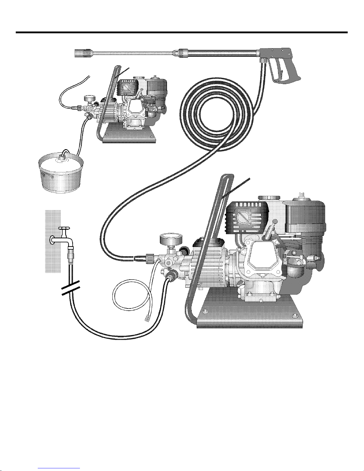
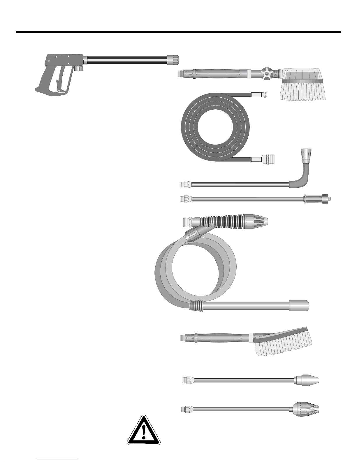
Item
3
water
8
9
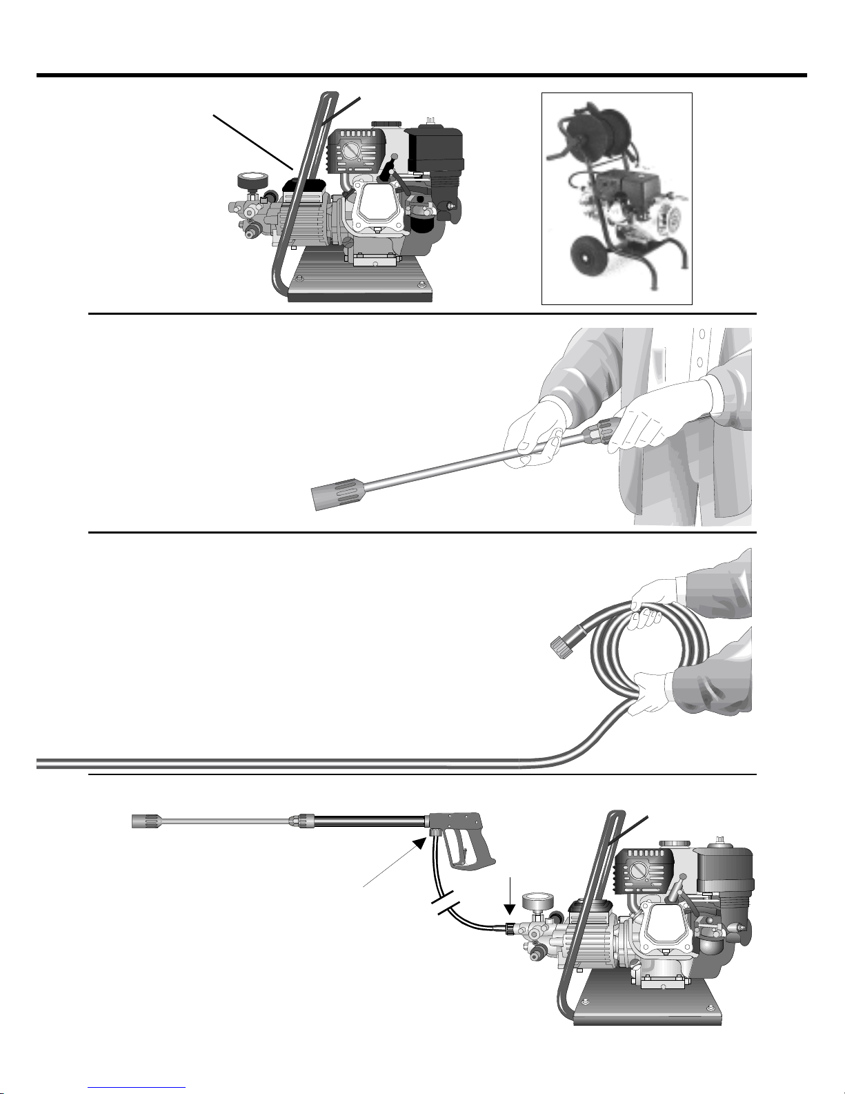
6 Injector for cleaning agents
(not with B10/200)
7 High pressure hose
8 Spray gun assembly
9 Interchangeable lance
10 Regulator nozzle
10a B10/200 only with dirt-killer
1 Water inlet connection with filter
2 Suction hose with filter
(special accessory) order No. 15.038 3
3 High pressure pump
4 Pressure gauge with glycerin filling
5 Unloader valve - safety valve
The KRÄNZLE B 10/200 + B 13/150 + B 16/220 - high pressure cleaners
are portable/mobile machines. The design can be seen from the diagram.
Construction
DescriptionDescription
DescriptionDescription
Description
1
2
3
4
5
6
7
10
Page 4

4
The machine can only be operated when the safety trigger is squeezed.
When the lever ist squeezed, the spray gun opens. The liquid is then pumped to the
nozzle. The spray pressure increases and quickly reaches the selected operating
pressure.
When the trigger ist released, the trigger gun closes and any further spraying of
liquid from the lance ist stopped.
The increase in pressure when the trigger gun is closed causes the unloader valvesafety valve to open. The pump remaines switched on and continues to pump liquid
through the pump at reducated pressure.
When the trigger gun ist opened, the unloader valve - safety valve closes and the
pump ressumes pressure spraying from the lance.
The trigger gun is a safety device. Repairs should only be performed by
qualified persons. Should replacement parts be required, use only
components authorized by the manufacturer .
Lance with trigger gun
The unloader valve - safety valve protects the machine from a build-up of excess
pressure, and is designed not to permit an excess pressure to be selected for
operating. The limit nut on the handle is sealed with a spray coating.
The operating pressure and spray rate can be steplessly adjusted by tuning the
handle.
Replacements, repairs, new adjustments and sealing should only be
performed by qualified persons.
Unloader valve - safety valve
Environmental, refuse disposal and water protection
regulations must be observed !
Water - and Cleang - Care System
Water can be connected at mains pressure to the high pressure pump or it can be
sucked directly from a storage tank.
The water is then forced under pressure by the high pressure pump to the lance.
The high pressure jet is formed by the nozzle at the end of the lance.
Cleaning and caring agents can be mixed with the water by a low pressure injector .
(not with B10/200)
DescriptionDescription
DescriptionDescription
Description
Page 5
DescriptionDescription
DescriptionDescription
Description
For the motor follow the HondaFor the motor follow the Honda
For the motor follow the HondaFor the motor follow the Honda
For the motor follow the Honda
operating manual onlyoperating manual only
operating manual onlyoperating manual only
operating manual only
..
..
.
Motor-safety:
(see Honda operating manual)
5
Honda motors are safe and reliable if they are operated correctly . Read the
operating manual carefully before using the motor and try to understand the
contents of the manual completely .
Not following this advice could lead to injuries or damage of the
equipment.
To avoid a possible fire hazard and to ensure the necessary ventilation
the motor has to be operated at a distance of at least 1 m from buildings
and objects. Inflammable objects have to be kept away from the
surrounding area of the motor .
Children and pets have to be kept away from the motor, as there is a
danger of suffering burns from hot motor parts and to be injured by
equipment driven by the motor.
Get to know the motor and especially learn how to switch it off quickly.
Do not allow persons to operate the motor who are not familiar with it.
When running your high pressure cleaner with hot water of 70° C raised
temperatures occur .
Do not touch the machine without safety gloves.
CAUTION !
Never use liquid containing solvents such as paint thinners, petrol, oil or
similar liquid matter. Pay attention to the instructions of the
manufacturers of the cleaning agents. The seals in the
machine are not resistant to solvents. The spray of solvents is
inflammable, explosive and poisonous.
Neither set up and operate the machine in rooms where there is a risk of
fire or explosion nor put it into puddles. Do not use the machine under
water .
CAUTION !
Setting up: Location
Page 6
6
DescriptionDescription
DescriptionDescription
Description
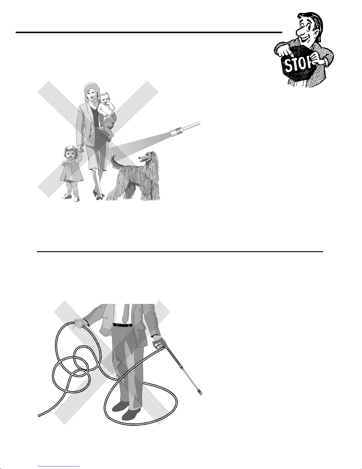
Brief operating instructions
1. Connect the high pressure hose with spray gun
and machine.
2. Connect the suitable water supply .
3. Flush the air from the pump (open and close the spray gun
several times).
4. Switch on the motor while the spray gun is open and commence
cleaning.
5. After completing the work, completely empty the pump
(switch the motor on for approximately 20 seconds without the
suction and pressure hose).
Afterwards you can roll up the high pressure hose.
- Only use clean water ! Protect from frost !
CAUTION !
Please pay attention to the regulations of your waterworks company .
In accordance with DIN 1988, the machine may not be directly connected to the
public drinking water supply lines.
A brief connection however ist permissible according to DVGW (German
Association for Gas and Water Affairs) if a tube ventilator with check valve
(KRÄNZLE Order-No. 41.016 4) is built into the water supply .
Also indirect connection to the public drinking water supply lines is permissible by
way of free emission in accordance with DIN 1988, part 4; e.g. by using a reservoir
with a float valve.
Direct connection to a non-drinking water supply line is permissible.
High pressure hose and spray device
The high pressure hose and spray device supplied with the machine are made of
high grade material, they are also optimized for the machine and marked as
required by the appropriate regulations.
If replacement parts are required, only such parts that are authorized by
the manufacturer and which bear the markings required by the
appropriate regulations may be used. The high pressure hose and spray
device must be connected in a pressure-tight manner . The high pressure
hose may not be driven over, pulled excessively, or twisted. The hose
may under no circumstances be pulled over sharp edges, since
otherwise the guarantee is automatically void.
Page 7

7
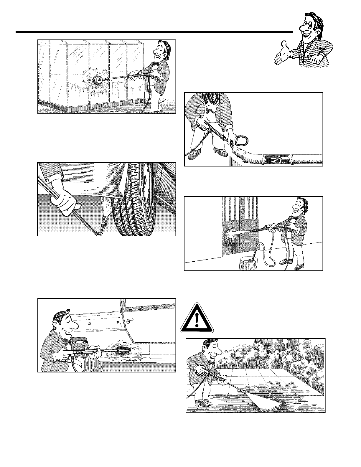
Always aim the
underbody lance. Note
when using an angle
underbody lance, like
for example lance
No. 41.075, that there
is a certain amount of
torque (twisting
motion) in the recoil.
(See also notice on
page 2).
As to the recoil see notice on page 2.
Apply the safety catch on the
spray gun after each use, in
order to prevent
unintentional spraying.
Safety notesSafety notes
Safety notesSafety notes
Safety notes
Page 8
8
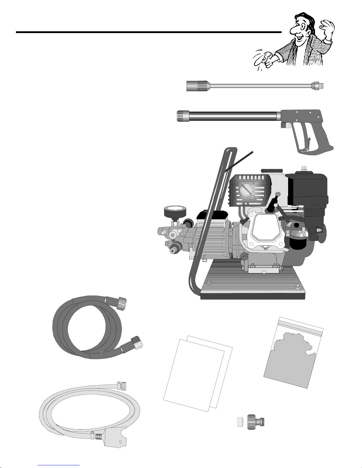
This is what you´ve purchased :This is what you´ve purchased :
This is what you´ve purchased :This is what you´ve purchased :
This is what you´ve purchased :
1. Spray lance with regulator and
high pressure nozzle, flat spray
(B10/200 only with dirt-killer)
2. Spray gun with insulated pistol
grip and screw connection
3. KRÄNZLE - High pressure cleaner
B 10/200 B 13/150 B 16/220
4. High pressure hose 10 m
15 m HP-hose for cleaners
with hose drum
5. Suction hose
6. Operating instructions pump
Operating instructions motor
7. Washing powder
specimen
8. Water inlet components
Page 9
9
1. Oil-measuring stick
Prepare for usePrepare for use
Prepare for usePrepare for use
Prepare for use
2. Connect the high pressure
lance to the spray gun.
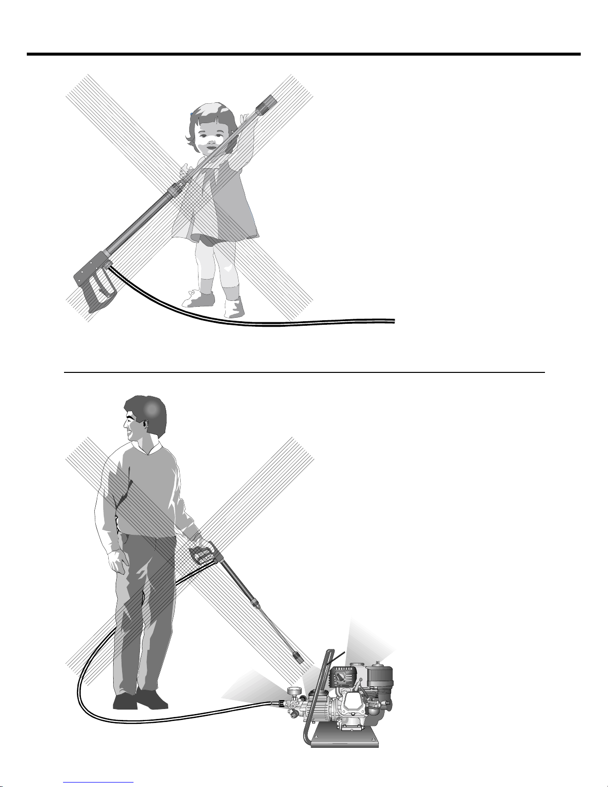
3. Unwind the high pressure hose
without leaving kinks or "nooses"
and connect it to the spray gun and
pump. When using extension
hoses, use max. 20 m high
pressure hose, or 2 x 10 m with
hose connectors.
The high pressure hose
connected from the machine to
the lance.
Page 10

10
Water
CAUTION !
5. Maximum induction height 2.5 m
- see technical data
on page 2.
Please make
sure that the filter is
clean before using
your
high pressure cleaner.
4. The machine can be connected
to a pressurised water line with cold
or 60 °C respectively 70 °C hot water
(see
page 2).
Ensure that the water supply ist clean
when sucking from external sources.
The hose cross section must be
at least 1/2" = 12.7 mm (free
passage). Filter 1 must
always be clean.
Preparation for usePreparation for use
Preparation for usePreparation for use
Preparation for use
When running your high pressure cleaner with hot water of 70° C raised
temperatures occur .
Do not touch the machine without safety gloves.
Page 11
11
Preparation for usePreparation for use
Preparation for usePreparation for use
Preparation for use
1. Switch off the machine
2. Cut off the water supply
3. Open the spray gun briefly until the pressure is released
4. Apply the safety catch on the spray gun
5. Remove the water hose and high pressure hose
6. Drain the pump: switch on the motor for approx. 20 seconds
7. Winter: store the pump in rooms above 0° C
8. Clean the water filter
To shut down the pump:
Note that you must always comply
with the instructions provided by the
manufacturer of the cleansing
agent (e.g. instructions
concerning safety clothing) and
the water protection egulations.
A mixing ratio of 3-5% is achieved
when the Vario-Jet is fully turned on.
pH value neutral 7-9.
Place chemical filter no. 5 in the reservoir with
the cleansing agent. Turn on Vario-Jet No. 4 to
enable the injector to induct the cleansing
agent. By turning back the Vario-Jet nozzle, the
supply of chemical is automatically cut off.
Allow the cleansing agent to take effect and
then remove with high pressure spray.
When using cleansing agents:
Adjusting the pressure
This is accomplished by turning the handwheel.
The default setting is maximum pressure.
p max.
Chem.
Turn on regulator nozzle
to reach low pressure.
Page 12
12
This is prohibitedThis is prohibited
This is prohibitedThis is prohibited
This is prohibited
Never allow
children to use the
high pressure
cleaner !
Never direct the
water jet at the
machine itself !
Page 13
13
Never direct the
water jet at people
or animals !
Never pull the high
pressure hose if it
has formed kinks or
"nooses"!
Never pull the hose
over sharp edges !
This is prohibitedThis is prohibited
This is prohibitedThis is prohibited
This is prohibited
Page 14
14
Additional KRÄNZLE accessoriesAdditional KRÄNZLE accessories
Additional KRÄNZLE accessoriesAdditional KRÄNZLE accessories
Additional KRÄNZLE accessories
(not with B 10/200)
Environmental, refuse disposal and water
protection regulations must be observed
when using the accessories.
Rotary scrubbing brush
Order No. 41.050 1
Sandblaster
Order No. 41.068 1
Underbody lance, new
Order No. 41.075
Flat brush
Order No. 41.073
Drain and pipe
cleaning hose
8 m - Order No. 41.051
15 m -
Order No. 41.058
Dirtkiller
B 10/200
Order No. 41.073 8
B13/150
Order No. 41.072 5
Turbokiller
B 16/220
Order No. 41.072 4
Page 15
15
for further combination possibilitiesfor further combination possibilities
for further combination possibilitiesfor further combination possibilities
for further combination possibilities
Car cleaning, glass, caravan, boat etc.:
rotary washing brush with 40 cm extension
and
ST 30 nipple M 22
Cleaning cars and all smooth surfaces:
brush with ST 30 nipple M 22.
Underbody cleaning of cars, trailers and
equipment: lance 90 cm with high pressure
nozzle and ST 30 nipple. The lance must
be aimed when spraying.
Blasting old paint, rust and facades:
sandblasting injector with suction lance and
3 m PVC hose and ST 30 nipple M 22.
Rotary point sprayer for extreme soiling:
dirt killer with 40 cm extension and
ST 30 nipple M 22.
Cleaning pipes, channels and drains: Pipe
cleaning hose with KN nozzle and
ST 30 nipple M 22.
When sandblasting you must
wear protection clothes! Pay
attention to the instructions of
the manufacturer of the
abrasive.
Page 16

16
Small repairs –Small repairs –
Small repairs –Small repairs –
Small repairs –
The pressure gauge shows a 10% higher pressure than the
working pressure.
The injector may be dirty
and you
should first
remove
the hose.
Now turn on the water
and you should get a
powerful stream of water,
but if you
only get a weak
flow of water
then straighten
a paper clip,
and release the
injector with an
open-ended
spanner.
Check that it
is clean.
Reconnect the hose,
and you are
ready to continue
your work.
Y ou only get a weak flow of water or no water at all !
Remove the injector
together with the
spring and return
valve.
Cleaning the injector through
from both sides and replace
the return valve.
Page 17

17
The nozzle is blocked !
No water but the gauge shows full pressure.
Rinse the hose through
first.
Y ou should now have
a powerful stream of
water,
remove the lance and
clean the
nozzle.
Using the flat spray lance
you only have to clean the front
nozzle.
Straighten a paper clip
and clean the nozzle.
Insert pointed opject
into the hole
and pull the cap back!
Check visually whether the
nozzle is clean.
Now it works as well
as before.
Do it yourself !Do it yourself !
Do it yourself !Do it yourself !
Do it yourself !
but if you only
get a few drops
of water from
the lance,
Page 18

18
Small repairs - Do it yourself !Small repairs - Do it yourself !
Small repairs - Do it yourself !Small repairs - Do it yourself !
Small repairs - Do it yourself !
Valve dirty or sticky !
Pressure gauge does not show full pressure.
Water comes out in spurts.
If you do not use the high pressure cleaner for some time the valves can stick.
Straighten a
paper clip...
the gauge
shows little
pressure or
no
pressure
at all.
or the high
pressure
hose vibrates!
Open the
valves with a
socket wrench...
remove the
valve screw, the
valve and the
O-ring.
Rplace the rubber
O-ring.
and remove the dirt
from the valve - the
inside must be
closed.
Retighten the
valve screw,
and repeat an
all 6 valves.
Now it works as
well as before.
The high-pressure hose
vibrates.
When a valve is blocked.
Page 19

19
General rulesGeneral rules
General rulesGeneral rules
General rules
The machine must be inspected according to the "Guidelines for Liquid
Spray Devices" at least once every 12 months by a qualified person, to
ensure that continued safe operation is guaranteed. The results of the
inspection are to be recorded in writing. This may be done in any form.
Inspections:
The machine is designed for accidents to be impossible if used correctly.
The operator is to be notified of the risk of injury from hot machine parts and
the high pressure water jet. The "Guidelines for Liquid Spray Devices" must
be complied with. (see page 12 and 13)
Accident prevention
Check the oil level with the oil-measuring stick prior to each
use.
(Ensure horizontal position!)
Oil change B10/200 ; B13/150:
No oil change is required during the working life of the machine. However,
should it be necessary to change the oil in the event of repairwork, the oil
sight glass is to be opened over a reservoir and the machine to be emptied.
The oil is to be caught in the reservoir and disposed of in the approved
manner.
New oil: 0,5 l - Motor oil W 15/40
Oil change B16/220:
The oil of your high pressure pump should be changed after approx. 40
hours of operation, or no later than when it takes an a grey or whitish colour.
Open the oilplug over a container and drain off all the oil. The oil must be
caught in a contianer and disposed of in a responsible, legal manner.
New oil: 1,0 l - Castrol Formula RS
The guarantee period is 12 months according to VDMA.
The guarantee is void if changes are made in the safety devices or if the
machine is used at excess temperatures or speeds. The guarantee is also
void if the machine is used with a voltage below the required rating, with less
than the required amount of water, with dirty water and external damage to
the pressure gauge, nozzle, high pressure hose and spray device.
This guarantee is not applicable for spare parts.
Our operating instructions must be complied with.
Guarantee
Page 20

20
Complete AssemblyComplete Assembly
Complete AssemblyComplete Assembly
Complete Assembly
Page 21

21
No. Description Qty. Ord.-No.
1 Wagen 1 41.101 5
2 Innensechskantschrtaube M 8 x 35 4 41.510
3 Schubbügel 1 41.101 3
6 Unterlegscheibe 8,4 8 41.515
7 Elastic-Stop-Mutter M 8 4 41.410
9 O-Ring 9,3 x 2,4 2 13.273
11 Hochdruckschlauch 10 m / DN 8 - 210
bar 1 41.081
12 Starlett II mit ISO-Handgriff 1 12.320 2
13 Lanze mit Vario-Jet 030 1 41.156 2
14 Lanze mit Schmutzkiller 030 1 41.073 8
16 Gummidämpfer 4 40.220
17 Starlock-Kappe 2 40.142
18 Rad luftbereift 2 40.141
19 Innensechskantschraube M 6 x 40 2 40.133
20 Flügelmutter M 6 2 40.132
21 Mutter M 5 1 41.416
22 Schraube M 5 x 40 1 41.415
23 Pistolenhalterung 1 40.130
26 Gummistopfen für Wagen 2 40.208 1
27 Bügel 1 41.101 6
28 Elastic-Stop-Mutter M 8 2 41.514
Motor Honda GX 200 LX 24.027 2
Spare parts list Profi-Jet B 10/200 with undercarriage
Complete Assembly
KRÄNZLE B 10/200KRÄNZLE B 10/200
KRÄNZLE B 10/200KRÄNZLE B 10/200
KRÄNZLE B 10/200
Page 22

22
TT
TT
T
ransmission unitransmission unit
ransmission unitransmission unit
ransmission unit
Page 23

23
No. Description Qty. Ord.-No.
22 Getriebegehäuse 1 41.481 1
23 Gehäuseplatte 15 mm 1 42.906
29 Axial-Rillenkugellager 3-teilig 2 43.486
34 Öldichtung 15 x 24 x 7 3 42.907
36 Plunger 15 mm 3 42.908
37 Plungerfeder 3 41.033
39 Federdruckscheibe 15 mm 3 42.909
40 Sprengring 15 mm 3 42.910
41 O-Ring Viton 88 x 2 1 41.021 1
45.1 Innensechskantschraube M 8 x 30 4 41.036 1
46 Ölablaßschraube M 18 x 1,5 1 41.011
47 O-Ring 12 x 2 1 15.005 1
48 Innensechskantschraube M 8 x 20 4 41.480
49 Kupferdichtring 4 41.500
51.1 Wellendichtring 25 x 35 x 5 1 41.019 5
52 Spannstift 1 14.148
53 Stufenkeil 1 41.183
54 Swash plate 13° 1 41.028 6-13,0
please specify swash plate angle when ordering
55 Ölschauglas M 18 x 1,5 1 42.018 1
56 Flachdichtung 1 41.019 3
57 Deckel 1 40.518
58 Ölmeßstab 1 42.520 1
59 Innensechskantschraube M 5 x 12 4 41.019 4
60 O-Ring 14 x 2 2 43.445
61 Sicherungsring 4 40.054
Spare parts list Profi-Jet B 10/200
T ransmission unit
Kränzle B 10/200Kränzle B 10/200
Kränzle B 10/200Kränzle B 10/200
Kränzle B 10/200
Page 24

24
VV
VV
V
alve housingalve housing
alve housingalve housing
alve housing
Page 25

25
No. Description Q t y. Ord.-No.
1 Ventilgehäuse 1 42.900
2 Ventilstopfen 6 41.714
3 Dichtstopfen M 10 x 1 1 43.043
4 Ventile (grün) für APG-Pumpe 6 41.715 1
5 O-Ring 16 x 2 8 13.150
6 O-Ring 15 x 2 6 41.716
7 Dichtstopfen R1/4" mit Bund 1 42.103
8 O-Ring 11 x 1,44 1 12.256
9 Edelstahlsitz 1 14.118
10 Sicherungsring 1 13.147
11 Edelstahlkugel 8,5 mm 1 13.148
12 Edelstahlfeder 1 14.119
13 Verschlußschraube 1 14.113
14 Steuerkolben 1 14.134
15 Parbaks 16 mm 1 13.159
16 Parbaks 8 mm 1 14.123
17 Spannstift 1 14.148
18 Kolbenführung spezial 1 42.105
19 Mutter M 8 x 1 2 14.144
20 Ventilfeder schwarz 1 14.125
21 Federdruckscheibe 1 14.126
22 Nadellager 1 14.146
23 Handrad 1 14.147
24 Manschette 15 x 24 x 5/2,7 braun 3 42.902
25 Elastic-Stop-Mutter 1 14.152
26 Manomter 0-250 bar 1 15.039
27 Druckring 15 mm 3
28 Manschette 15 x 24 x 5/2,7 schwarz 3 42.902 1
29 Backring 15 x 24 6 42.903
30 O-Ring 28,3 x 1,78 3 40.026
31 Leckagering 15 mm 3 42.905
No. Description Qty. Ord.-No.
32 Zwischenring 15 mm 3 42.904 1
33 O-Ring 15 x 1,5 1 42.104
34 O-Ring 6 x 3 1 14.121
35 Rückschlagkörper 1 14.122
36 Rückschlagfeder 1 14.120
37 O-Ring 18 x 2 1 43.446
38 Ausgangsstück Injektor ST30 M22x1,5 1 43.447
39 Saugzapfen Schlauchanschluß 1 13.236
40 Edelstahlkugel 5,5 mm 1 13.238
41 Edelstahlfeder 1 13.239
42 Kupferring 1 42.104
43 Innensechskantschraube M 8 x 30 2 41.036 1
44 Innensechskantschraube M 8 x 55 2 41.017 1
45 Sicherungsring 4 40.054
46 Sauganschluß 1 41.016
47 Wasserfilter 1 41.046 1
48 Gummi Dichtring 1 41.047 1
49 Steckkupplung 1 41.047 2
50 O-Ring 1 41.047 3
51 Aluminium-Dichtring 2 13.275
Repair kit Valves for APG-Pump 41.748 1
consisting of 6x No. 4; 6x No. 5; 6x No. 6
Repair kit sleeves 15 mm 41.049 1
consisting of 3x No. 24; 3x No. 27;
3x No. 28; 6x No. 29; 6x No. 30
Valve housing compl. 42.912
with integr. ULH and pressure switch
Piston valve compl. with Handwheel 43.444
Spare parts list Profi-Jet B 10 / 200
V alve housing APG 15 mm
Kränzle B 10/200Kränzle B 10/200
Kränzle B 10/200Kränzle B 10/200
Kränzle B 10/200
Page 26

26
Complete AssemblyComplete Assembly
Complete AssemblyComplete Assembly
Complete Assembly
Page 27

27
Kränzle B 13/150Kränzle B 13/150
Kränzle B 13/150Kränzle B 13/150
Kränzle B 13/150
No. Description Qty. Ord.-No.
1 Wagen 1 41.101 2
1a Wagen kompl. (Pos. 1 + 3) 1 41.101 5
2 Sechskantschraube M 8 x 40 4 41.510
3 Schubbügel 1 41.101 3
6 Unterlegscheibe 8,4 8 41.515
7 Elastic-Stop-Mutter M 8 4 41.410
8 Hochdruckschlauch 1m / DN 8 - 210 bar 1 41.265
9 O-Ring 9,3 x 2,4 2 13.273
10 Chemiesieb mit 1,2 m PVC-Schlauch 1 15.038
11a at unit with hose drum
high pressure hose 20 m / DN 8 - 210 bar1 41.083
11b at unit without hose drum
high pressure hose 10 m / DN 6 - 210 bar1 43.416
12 Pistole mit Verlängerung 1 41.053 1
13 Lance with reg. nozzle 25055 1 41.053 2
prease specify size of nozzle
14 Saugschlauch 3 m mit Saugfilter 1 15.038 3
15 Schmutzkiller 055 1 41.072 6
16 Gummidämpfer 4 40.220
17 Starlock-Kappe 2 40.142
18 Rad luftbereift 2 40.141
19 Innensechskantschraube M 6 x 40 2 40.133
20 Flügelmutter M 6 2 40.132
21 Mutter M 6 1 14.127 1
22 Innensechskantschraube M 6 x 40 1 40.133
23 Pistolenhalterung 1 40.130
24 Schraube 2,9 x 19 2 15.024
25 Schlauchtrommel 1 41.259
26 Gummistopfen 2 40.208 1
27 Bügel 1 41.101 6
28 Elastic-Stop-Mutter M 8 2 41.514
Motor Honda GX 160 CX 24.027
Upgrade kit hose drum 41.259 1
with 1 m HP-Connection hose
but without 20 m HP-hose
Spare parts list Profi-Jet B 13/150 with undercarriage
Complete Assembly
Page 28

28
Complete AssemblyComplete Assembly
Complete AssemblyComplete Assembly
Complete Assembly
Page 29

29
KRÄNZLE B 13/150KRÄNZLE B 13/150
KRÄNZLE B 13/150KRÄNZLE B 13/150
KRÄNZLE B 13/150
No. Description Qty. Ord.-No.
1 Tragbügel 1 41.098 3
2 Sechskantschraube M 8 x 40 4 41.510
3 Unterlegscheibe 6 mm 4 41.511
4 Elastic-Stop-Mutter M 6 4 14.152 1
5 Gummifüße 4 41.513
6 Unterlegscheiben 8 mm 4 41.515
7 Elastic-Stop-Mutter M 8 4 41.410
8 Unterlegscheiben 6 mm (groß) 16 41.516
9 O-Ring 9,3 x 2,4 2 13.273
10 Chemiesieb mit 1,2 m PVC-Schlauch 1 15.038
11 Hochdruckschlauch 10 m / DN 6 - 210 bar1 43.416
12 Pistole mit Verlängerung 1 41.053 1
13 Lanze mit Regeldüse 25055 1 41.053 2
prease specify size of nozzle
14 Saugschlauch 3 m mit Saugfilter 1 15.038 3
Motor Honda GX 160 CX 24.027
Spare parts list Profi-Jet B 13/150 portable
Complete Assembly
Page 30

30
TT
TT
T
ransmission unitransmission unit
ransmission unitransmission unit
ransmission unit
Page 31

31
No. Description Qty. Ord.-No.
22 Getriebegehäuse 1 41.481 1
23 Gehäuseplatte 18 mm 1 41.020 2
29 Axial-Rillenkugellager 3-teilig 2 43.486
34 Öldichtung 18 x 28 x 7 3 41.031
36 Plunger 18 mm 3 41.032 1
37 Plungerfeder 3 41.033
39 Federdruckscheibe 18 mm 3 41.034
40 Sprengring 18 mm 3 41.035
41 O-Ring Viton 88 x 2 1 41.021 1
45.1 Innensechskantschraube M 8 x 30 4 41.036 1
46 Ölablaßschraube M 18 x 1,5 1 41.011
47 O-Ring 12 x 2 1 15.005 1
48 Innensechskantschraube M 8 x 20 4 41.480
49 Kupferdichtring 4 41.500
51.1 Wellendichtring 25 x 35 x 5 1 41.019 5
52 Spannstift 1 14.148
53 Stufenkeil 1 41.183
54 Taumelscheibe 11,5° 1 41.028 6-11,5
please specify swashplate angle when ordering
55 Ölschauglas M 18 x 1,5 1 42.018 1
56 Flachdichtung 1 41.019 3
57 Deckel 1 40.518
58 Ölmeßstab 1 42.520 1
59 Innensechskantschraube M 5 x 12 4 41.019 4
60 O-Ring 14 x 2 2 43.445
61 Sicherungsring 4 40.054
Motor Honda GX 160 24.027
Spare parts list Profi-Jet B 13/150
Antrieb
KRÄNZLE B 13/150KRÄNZLE B 13/150
KRÄNZLE B 13/150KRÄNZLE B 13/150
KRÄNZLE B 13/150
Page 32

32
VV
VV
V
alve housingalve housing
alve housingalve housing
alve housing
Page 33

33
KRÄNZLE B 13/150KRÄNZLE B 13/150
KRÄNZLE B 13/150KRÄNZLE B 13/150
KRÄNZLE B 13/150
No. Description Q t y. Ord.-No.
1 Ventilgehäuse 1 43.435
2 Ventilstopfen 6 41.714
3 Dichtstopfen M 10 x 1 1 43.043
4 Ventile (grün) für APG-Pumpe 6 41.715 1
5 O-Ring 16 x 2 8 13.150
6 O-Ring 15 x 2 6 41.716
7 Dichtstopfen R1/4" mit Bund 1 42.103
8 O-Ring 11 x 1,44 1 12.256
9 Edelstahlsitz 1 14.118
10 Sicherungsring 1 13.147
11 Edelstahlkugel 8,5 mm 1 13.148
12 Edelstahlfeder 1 14.119
13 Verschlußschraube 1 14.113
14 Steuerkolben 1 14.134
15 Parbaks 16 mm 1 13.159
16 Parbaks 8 mm 1 14.123
17 Spannstift 1 14.148
18 Kolbenführung spezial 1 42.105
19 Mutter M 8 x 1 2 14.144
20 Ventilfeder schwarz 1 14.125
21 Federdruckscheibe 1 14.126
22 Nadellager 1 14.146
23 Handrad 1 14.147
25 Elastic-Stop-Mutter 1 14.152
26 Manomter 0-250 bar 1 15.039
27 Druckring 3 41.018
28 Manschette 18 x 26 x 4/2 3 41.013
28.1 Gewebemanschette 18 x 26 x 4/2 3 41.013 1
29 Backring 18 x 26 6 41.014
30 O-Ring 28,3 x 1,78 3 40.026
31 Leckagering 18 mm 3 41.066
No. Description Qty. Ord.-No.
32 Zwischenring 18 mm 3 41.015 2
33 O-Ring 15 x 1,5 1 42.104
34 O-Ring 6 x 3 1 14.121
35 Rückschlagkörper 1 14.122
36 Rückschlagfeder 1 14.120
37 O-Ring 18 x 2 1 43.446
38 Ausgangsstück Injektor ST30 M22x1,5 1 43.447
39 Saugzapfen Schlauchanschluß 1 13.236
40 Edelstahlkugel 5,5 mm 1 13.238
41 Edelstahlfeder 1 13.239
42 Kupferring 1 42.104
43 Innensechskantschraube M 8 x 30 2 41.036 1
44 Innensechskantschraube M 8 x 55 2 41.017 1
46 Sauganschluß 1 41.016
47 Wasserfilter 1 41.046 1
48 Gummi Dichtring 1 41.047 1
49 Steckkupplung 1 41.047 2
50 O-Ring 1 41.047 3
51 Aluminium-Dichtring 2 13.275
Repair kit Valves for APG-Pump 41.748 1
consistion of 6x No. 4; 6x No. 5; 6x No. 6
Repair kit sleeves 18 mm 41.049 2
consisting of 3x No. 27; 3x No. 28;
3x No. 28.1; 6x No. 29; 6x No. 30
Valvehousing compl. 43.442
with integr. ULH
Piston walve compl. with handwheel 43.444
Spare parts list Profi-Jet B 13/150
V alve housing APG 18 mm
Page 34

34
Complete AssemblyComplete Assembly
Complete AssemblyComplete Assembly
Complete Assembly
Page 35

35
No. Description Qty. Ord.-No.
1 Wagen 1 41.101 2
1a Wagen kompl. (Pos. 1 + 3) 1 41.101 5
2 Sechskantschraube M 8 x 30 4 40.221
3 Schubbügel 1 41.101 3
6 Unterlegscheibe 8,4 8 41.515
7 Elastic-Stop-Mutter M 8 4 41.410
8 Hochdruckschlauch 1m / DN 8 - 210 bar 1 41.265
9 O-Ring 9,3 x 2,4 3 13.273
10 Chemiesieb mit 1,2 m PVC-Schlauch 1 15.038
11a at unit with hose drum
high pressure hose 15 m / DN 8 - 210 bar1 41.083
11b at unit without hose drum
high pressure hose 10 m / DN 8 -210 bar 1 41.082
12 Starlett II mit ISO-Handgriff 1 12.320 2
13 Lance with reg. nozzle 25055 1 41.053 2
prease specify size of nozzle
14 Saugschlauch 3 m mit Saugfilter 1 15.038 3
15 Turbokiller 055 1 41.072 4
16 Gummidämpfer 4 40.220
17 Starlock-Kappe 2 40.142
18 Rad luftbereift 2 40.141
19 Innensechskantschraube M 6 x 40 2 40.133
20 Flügelmutter M 6 2 40.132
21 Mutter M 6 1 14.127 1
22 Innensechskantschraube M 6 x 40 1 40.133
23 Pistolenablage 1 40.130
24 Schraube 2,9 x 19 2 15.024
25 Schlauchtrommel kpl. ohne Schlauch 1 41.259
26 Gummistopfen 2 40.208 1
27 Bügel 1 41.101 6
28 Elastic-Stop-Mutter M 8 2 41.514
Speedcontrol with 1m Bowden cable 1 40.255 1
Motor Honda GX 340 24.026
AQ-Pump compl. 40.265
Upgrade kit hose drum 41.259 1
with 1 m HP-Connection hose
but without 20 m HP-hose
Spare parts list Profi-Jet B 16/220 with undercarriage
Complete Assembly
KRÄNZLE B 16/220KRÄNZLE B 16/220
KRÄNZLE B 16/220KRÄNZLE B 16/220
KRÄNZLE B 16/220
Page 36

36
TT
TT
T
ransmission unitransmission unit
ransmission unitransmission unit
ransmission unit
Page 37

37
No. Description Qty. Ord.-No.
1 Ölgehäuse 1 40.501
2 Cu-Dichtring 1 40.052
3 Ölablaßschraube 1 40.051
4 Innensechskantschraube M 8 x 25 6 40.053
5 Sicherungsscheibe 6 40.054
6 Flachdichtung 1 40.511
7 Öldichtung 20 x 30 x 7 3 40.044 1
8 Wellenscheibe 1 40.043
9 Axial-Rollenkäfig 1 40.040
10 AS-Scheibe 2 40.041
11 Swash plate 8° 1 40.042 6-8,0
please specify swash plate angle when ordering
12 Plungerfeder 3 40.506
13 Federdruckscheibe 3 40.510
14 Plunger 20 mm (lang) 3 40.505
15 Sprengring 3 40.048
16 O-Ring 14 x 2 2 43.445
17 Ölschauglas M 18 x 1,5 1 42.018
18 Flachdichtung 1 41.019 3
19 Deckel Ölgehäuse 1 40.518
20 Innensechskantschraube M 5 x 12 4 41.019 4
21 Ölmeßstab 1 42.520
22 Stützscheibe 3 40.513
24 Gehäusescheibe 1 40.039
25 Innensechkantschraube M 8 x 30 4 41.036 1
26 Kupfer-Dichtring 4 41.500
27 Dichtring 30 x 42 x 7 1 40.224
28 Flansch für B 16/220 1 40.223
30 Motor Honda GX 340 1 24.026
52 Spannstift 1 14.148
53 Stufenkeil 1 40.222
Spare parts list Profi-Jet B 16/220
T ransmission unit AQ-Pump
KRÄNZLE B 16/220KRÄNZLE B 16/220
KRÄNZLE B 16/220KRÄNZLE B 16/220
KRÄNZLE B 16/220
Page 38

38
VV
VV
V
alve housingalve housing
alve housingalve housing
alve housing
Page 39

39
KRÄNZLE B 16/220KRÄNZLE B 16/220
KRÄNZLE B 16/220KRÄNZLE B 16/220
KRÄNZLE B 16/220
No. Description Qty. Ord.-No.
1 Ventilgehäuse AQ mit integr. UL 1 40.521
ohne integr. Druckschalter
2 O-Ring 18 x 2 6 40.016
3 Einlaß- / Auslaß- Ventil 6 42.024
4 O-Ring 21 x 2 6 42.025
5 Ventilstopfen 5 42.026
5.1 Ventilstopfen mit R 1/4" IG 1 42.026 2
6 Sicherungsring 4 40.032
7 Innensechskantschraube M 12 x 45 4 40.504
8 Sauganschluß R 1/2" AG 1 41.016 1
9 Wassereingangsfilter 1 41.046 2
13 Gewebemanschette 3 40.023
14 Backring 20 mm 6 40.025
15 O-Ring 31,42 x 2,62 3 40.508
16 Leckagering 20 x 36 x 13,3 3 40.509
17 Cu-Dichtring 21 x 28 x 1,5 1 42.039
18 Gummimanschette 3 40.512
19 Verschlußschraube R 1/2" 1 42.032
20 Distanzring mit Abstützung 3 40.507
23 Druckring 20 mm 3 40.021
24 Zwischenring 20 mm 3 40.516
29 Dichtring 17 x 22 x 1,5 (Kupfer) 1 40.019
30 Anschlußmuffe 3/8" AG x 3/8" IG by 1 13.136
version with control speed
30.1 Verschlußschraube 3/8" AG by 1 40.018
version without control speed
No. Description Qty. Ord.-No.
31 Dichtstopfen M 10 x 1 1 43.043
34 O-Ring 6 x 3 1 14.121
35 Rückschlagkörper 1 14.122
36 Rückschlagfeder 1 14.120
37 O-Ring 18 x 2 1 43.446
38 Ausgangsstück Injektor ST30 M22x1,5 1 43.447
39 Saugzapfen Schlauchanschluß 1 13.236
40 Edelstahlkugel 5,5 mm 1 13.238
41 Edelstahlfeder 1 13.239
48 Gummidichtung für Steckkupplung 1 41.047 1
49 Steckkupplung für Wassereingang 1 41.047 2
49.1 Steckkupplung kpl. 41.047 4
Pos. 10 - 12
50 O-Ring 1 41.047 3
Repair kit sleeves 40.065 1
consisting of: 3x No. 13; 6x No. 14;
3x No. 15; 3x No. 16; 3x No. 18;
3x No. 20; 3x No. 23
Repair kit sleeves without 40.517
brassparts consisting of:
3x No. 13; 6x No. 14; 3x No. 15;
3x No. 18; 3x No. 23
Repair kit Valves 40.062 1
consisting of:
6x No. 2; 6x No. 3; 6x No. 4
Spare parts list Profi-Jet B 16/220
V alve housing AQ-Pump
Page 40

40
UnloadervalveUnloadervalve
UnloadervalveUnloadervalve
Unloadervalve
Page 41

41
Spare parts list Profi-Jet B 16/220
Unloadervalve AQ-Pump
KRÄNZLE B 16/220KRÄNZLE B 16/220
KRÄNZLE B 16/220KRÄNZLE B 16/220
KRÄNZLE B 16/220
No. Description Qty. Ord.-No.
5 O-Ring 16 x 2 2 13.150
8 O-Ring 11 x 1,44 1 12.256
9 Edelstahlsitz 1 14.118
10 Sicherungsring 1 13.147
11 Edelstahlkugel 1 13.148
12 Edelstahlfeder 1 14.119
13 Verschlußschraube 1 14.113
14 Steuerkolben 1 14.134
15 Parbaks 16 mm 1 13.159
16 Parbaks 8 mm 1 14.123
17 Spanstift 1 14.148
18 Kolbenführung spezial 1 42.105
19 Kontermutter M 8 x 1 2 14.144
20 Ventilfeder schwarz 1 14.125
21 Federdruckscheibe 1 14.126
22 Nadellager 1 14.146
23 Handrad 1 14.147
25 Elastic-Stop-Mutter M 8 x 1 1 14.152
26 Manometer 0-400 Bar 1 15.039 4
27 Aluminium-Dichtring 2 13.275
Page 42

42
Hose drumHose drum
Hose drumHose drum
Hose drum
Page 43

43
KRÄNZLE B 13/150 B 16/220KRÄNZLE B 13/150 B 16/220
KRÄNZLE B 13/150 B 16/220KRÄNZLE B 13/150 B 16/220
KRÄNZLE B 13/150 B 16/220
No. Description Qty. Ord.-No.
1 Seitenschale Schlauchführung 1 40.302
2 Seitenschale Wasserführung 1 40.301
3 Trommel Unterteil 1 40.304
4 Trommel Oberteil 1 40.303
5 Innensechskantschraube M 4 x 25 4 40.313
6 Lagerklotz mit Bremse 1 40.306
7 Lagerklotz links 1 40.305
8 Klemmstück 2 40.307
9 Kunststoffschraube 5,0 x 20 12 43.018
10 Antriebswelle 1 40.310
11 Welle Wasserführung 1 40.311
12 Elastic-Stop-Mutter M 4 4 40.111
13 Handkurbel 1 40.309
14 Verriegelungsbolzen 1 40.312
15 Scheibe MS 16 x 24 x 2 1 40.181
16 Wellensicherungsring 22 mm 2 40.117
17 Wellensicherungsring 16 mm 1 40.182
20 Parbaks 16 mm 2 13.159
21 Sicherungsscheibe 6 DIN6799 1 40.315
22 Schraube M 5 x 10 1 43.021
23 Drehgelenk 1 40.167
24 Anschlußteil 1 40.308 1
25 Distanzring 1 40.316
27 O-Ring 6,68 x 1,78 1 40.585
33 O-Ring 6 x 1,5 1 13.386
34 Stopfen M 10 x 1 1 13.385
42 O-Ring 9,3 x 2,4 4 13.273
45 Hochdruckschlauch 20 m NW 8 1 41.083
Spare parts list Profi-Jet B 13/150; B 16/220
Hose Drum
Page 44

44
Speed controlSpeed control
Speed controlSpeed control
Speed control
No. Description Qty. Ord.-No.
1 Grundteil 1 42.581
2 Druckhülse 1 42.584
4 Steuerkolben 1 42.582
5 Querbolzen 1 42.583
6 Druckfeder 2,0 x 9,5 x 70 1 42.587
7 Gewindestift M4 x 6 DIN 913-A2 1 42.592
8 Parbaks 7 mm 1 15.013
9 Bowdenzug 1 m 1 42.586
10 Unterlegscheibe 6,4 DIN 125 1 50.189
11 Sechskantmutter M6 DIN 934 1 14.127 1
12 Anschlussmuffe Drehzahlregulierung 1 42.585
13 Überwurfmutter 1 40.075
14 Klemmhülse 1 40.074
15 Einschraubwinkelverschraubung 3/8"x 12l 1
44.092
16 Drosselscheibe 1 42.589
17 Gewindestift M 6 x 12 DIN915 1 42.590
18 Klemmbolzen 1 42.591
Spare parts list Profi-Jet B 16/220
Speed control
Page 45

45
Starlet II - PistoleStarlet II - Pistole
Starlet II - PistoleStarlet II - Pistole
Starlet II - Pistole
No. Description Qty. Ord.-No.
1 Ventilkörper mit Handgriff 1 12.294
2 Schutzhülse 1 12.295
3 Abdeckschutz 1 12.296
4 Betätigungshebel 1 12.298
5 Sicherungshebel 1 12.149
6 Abschlußschraube M 16 x 1 1 12.247
7 Stopfen 1 12.287
8 Gewindeführungshülse R 1/4" AG 1 12.250
9 Aufsteuerbolzen 1 12.284
10 Stift 1 12.148
11 Lagernadel 1 12.253
12 Edelstahlfeder 1 12.246
13 Edelstahlkugel 1 12.245
14 Edelstahlsitz 1 13.146
15 O-Ring 11 x 1,44 1 12.256
16 O-Ring 3,3 x 2,4 1 12.136
17 Blechschraube 3,9 x 8 4 12.297
18 Druckstück 1 12.252
19 Rohr kunststoffumspritzt 1 15.004 5
bds. R 1/4" AG
20 Überwurfmutter ST30 M 22 x 1,5 IG 1 13.276 1
21 Außen-Sechskant-Nippel R 1/4" IG 1 13.277 1
22 O-Ring 9,3 x 2,4 1 13.273
23 Aluminium-Dichtring 4 13.275
24 O-Ring 15 x 1,5 1 12.129 1
25 Sicherungsring 1 12.258
Starlet - Gun with extention 12.320 2
Repair kit "Starlet II" 12.299
consisting of No. 9,10,13,14,15
Spare parts list Profi-Jet B 10/200; B 16/220
Starlet II
Page 46

TT
TT
T
urbokillerurbokiller
urbokillerurbokiller
urbokiller
46
No. Description Qty. Ord.-No.
11 Sprühkörperschutz 1 41.528
12 Sprühkörper 1 41.529
13 O-Ring 6,88 x 1,68 1 41.521
14 Düsensitz 1 41.522
15 Düse 055 1 41.532
16 Ring 1 41.533
17 Rotor 1 41.534
18 Stabilisator 1 41.524
19 O-Ring 41 x 1,78 1 41.538
20 Deckel 1 41.539
21 Deckelschutz 1 41.540
22 Rohr 500 mm lang; bds. R1/4" 1 12.385 1
23 Nippel M22x1,5 x R1/4" IG 1 13.370
Turbokiller 055 compl. with Lance 41.072 4
Rep. kit Turbokiller 055 41.097 1
Spare parts list Profi-Jet B 16/220
T urbokiller 055
Page 47

47
Standard regulation nozzleStandard regulation nozzle
Standard regulation nozzleStandard regulation nozzle
Standard regulation nozzle
No. Description Qty. Ord.-No.
30 Nippel ST30 M22x1,5 AG / M 12 x 1 1 13.363
31 Rohr 400 mm, bds. M 12 x 1 1 15.002
32 Regeldüse mit Regulierring 1 13.201 2
33 Flat spray nozzle 2505 1 26.001
Please specify size of nozzle
Spare parts list Profi-Jet B 13/150; B 16/220
Standard reg. nozzle
Page 48

48
PICO - GunPICO - Gun
PICO - GunPICO - Gun
PICO - Gun
No. Description Qty. Ord.-No.
1 Handgriff mit Ventilkörper 1 12.165
2 Abdeckung seitlich 1 12.166
3.1 Rohranschlußteil R1/4" 1 12.125
3a+b Messinghülse mit Teflonsitz 1 12.127
4 O-Ring 12 x 2 1 15.005 1
5 Abdeckung unten 1 12.167
6 Druckplatte 1 12.168
7 Abzug-Hebel 1 12.169
8 Messing-Scheibe 1 12.135
9 O-Ring 3,3 x 2,4 1 12.136
10 Sicherungshebel 1 12.170
11 Stift 3 x 17 1 12.171
12 Kontermutter M 4 2 12.138
13 Schraube 3,9 x 9,5 4 12.172
14 ST 30-Nippel M22 x 1,5 / R 1/4" AG 1 13.365
15 Rohr kunststoffumspritzt 1 15.004 2
bds. R 1/4" AG
16 Überwurfmutter ST 30 M22 x 1,5 IG 1 13.276 1
17 Außen-Sechskant-Nippel R 1/4" IG 1 13.277 1
18 O-Ring 9,3 x 2,4 1 13.273
21 Kolbenstange mit Kolben 1 12.143
22 Druckfeder 1 12.145
28 Aluminium-Dichtring 4 13.275
Pico-Gun with extention 41.053 1
Repair kit "Pico" 12.158
consisting of 1x No.:
3.1, 3a, 3b, 4, 8, 9, 12, 21, 22
Spare parts list Profi-Jet B 13/150
PICO-Gun
Page 49

49
DirtkillerDirtkiller
DirtkillerDirtkiller
Dirtkiller
No. Description Qty. Ord.-No.
1 Sprühkörper 1 41.520
2 O-Ring 6,88 x 1,68 1 41.521
3 Düsensitz 1 41.522
4 Düse 045 (B13/150) 1 41.523
4.1 Düse 03 (B 10/200) 1 41.523 4
5 Stabilisator 1 41.524
6 O-Ring 1 40.016 1
7 Sprühstopfen 1 41.526
8 Rohr 400 mm 2x M 12 x 1 1 41.527
9 ST 30-Nippel M 22 x 1,5 / M 12 x 1 ISK 1 13.363
Repair kit Dirtkiller 045 (B13/150) 41.097
consisting of No. 2; 3; 4; 5
Repair kit Dirtkiller 03 (B13/150) 41.096 1
consisting of No. 2; 3; 4.1; 5
Dirtkiller 045 with Lance (B13/150) 41.072 5
Dirtkiller 03 with Lance (B10/200) 41.073 8
Spare parts list Profi-Jet B 10/200; B 13/150
Dirtkiller
Page 50

50
for KRÄNZLE - High Pressure Cleaners
Regular inspection every 12 months if used professionally!
Appliance No: T ype:
The following must be checked:
1. Safety features
a) Manometer
b) Safety valve (pressure control)
c) Operating pressure
d) Cut out pressure (max. 10% above
operating pressure)
e) Low pressure with trigger released
2. General condition
a) High pressure hose
b) Spray gun
c) Motor
d) Oil level
Result of
inspection:
Date of inspection:
Faults rectified,
Stamp and signature
Excerpt from the Guidelines for Liquid Spray Equipment (ZH 1/46) by the Central Office of
the Professional Trade Association.
Inspection:
Liquid spray equipment should be inspected for safe operation by a qualified person
whenever necessary, but no less than every 12 months. The maker’s or supplier’s
instructions must be followed. The inspection intervals may be extended if the equipment
is not in active use.
In Germany, inspections compliant with the (German) Emission Controls Act may be
required for oil and gas-fired equipment, and the owner must arrange for these to be
carried out independently of the main inspection.
The results of inspections must be recorded in writing and presented to the respective
authorities on demand. There is no set form for these records.
The information in the operating instructions are a part of the inspection
Inspirection reportInspirection report
Inspirection reportInspirection report
Inspirection report
Page 51

I. Kränzle GmbH
Elpke 97 . 33605 Bielefeld
Herewith we B 10/200, B 13/150 and
declare that B 16/220
complies with the following 91/368 EEC ann. I No. 1
provisions applying to it 73/23 EEC
79/113 EEC 81/1051 EEC
89/336 EEC
Applied EN 292 T 1 and T 2
harmonized standards EN 60 204 T 1
in particular EN 50 082-2
EN 61 000 3-2 3-3 4-12
EN 55 014
EN 55 104
Applied national technical DIN VDE 0700 part 265/79 3.95
standards and specifications DIN IEC 61 S (Co) 17
in particular DIN IEC 801 2-6 601 1-2
DIN IEC 1000 4 2-11
Notified body
1)
within the TÜV Hannover
meaning of Annex VII
engaged for
2)
- safe keeping of the file as defined by Annex VI
- verification of correct application of harmonized standards and certification
of adequacy of the file as defined by Annex VI
- EC type-examination (EC type-examination certificate No. ...)
Bielefeld, 10.10.97
High-pressure-cleaners
Nettoyeurs à haute pression
Hochdruckreiniger
EC declaration of conformity
as defined by machinery directive 89/392/EEC, Annex II A
and the EC low-voltage directive 73/23 EEC
and the EC-EMC directive 89/336 EEC
(Managing Director)
Page 52

Reprint only allowed with the authorization of .
As date of 10. 05. 2001
Order n°.: 30 212 1
 Loading...