

Page 1

Reprint only allowed with the authorization of .
As of date of 20. 01. 2000
High Pressure Cleaners
Operating manualOperating manual
Operating manualOperating manual
Operating manual
Read and conform Read and conform
Read and conform Read and conform
Read and conform
safety instructions safety instructions
safety instructions safety instructions
safety instructions
before use before use
before use before use
before use
GB
Page 2
Dear Customer
We would like to congratulate you on your new high pressure cleaner with integrated undercarriage and to thank you for the purchase.
To ease your introduction to the use of the cleaner, we have provided the following
pages of explanations, tips and hints, which we ask you to read before using for the
first time.
The equipment will assist you professionally in all cleaning tasks, e.g.:
- facades
- flagstones
- terasses
-
vehicles of all types
- sheds
- machines etc.
- barrels and containers
- channels
Operating pressure
steplessly adjustable
Permis. overpressure
Water output
Hot water input
Temp.inducted water
Suction height
High pressure hose
Electrical ratings
Connect. Watt. Input
Output
Weight
Dimens. with moun-
ted Handel in mm
Sound lever accord.
to DIN 45 635 (rel. to
working place)
with dirtkiller
Recoil at lance
Torque
Oder No.
10 - 170 bar
190 bar
15 l/min
at 1700 rpm
max. 80 °C
max. 60 °C
2,5 m
20 m
220 V ; 60 Hz ;
23 A
P1: 5,5 kW
P2: 4,0 kW
82 kg
480 x 430 x 1120
89 dB
93 dB
appr. 20 Nm
22 Nm
Kränzle
2170 TST
Technical
specifications
Kränzle
3200 TST
Kränzle
3250 TST
Kränzle
3270 TST
10 - 180 bar
200 bar
19 l/min
at 1400 rpm
max. 80 °C
max. 60 °C
2,5 m
20 m
400 V ; 50 Hz ;
12 A
P1: 7,5 kW
P2: 5,5 kW
82 kg
480 x 430 x 1120
89 dB
93 dB
appr. 22 Nm
24 Nm
40.401
10 - 220 bar
250 bar
15 l/min
at 1400 rpm
max. 80 °C
max. 60 °C
2,5 m
20 m
400 V ; 50 Hz ;
12 A
P1: 7,5 kW
P2: 5,5 kW
82 kg
480 x 430 x 1120
89 dB
93 dB
appr. 25 Nm
26 Nm
40.402
10 - 250 bar
270 bar
13 l/min
at 1400 rpm
max. 80 °C
max. 60 °C
2,5 m
20 m
400 V ; 50 Hz ;
12 A
P1: 7,5 kW
P2: 5,5 kW
82 kg
480 x 430 x 1120
89 dB
93 dB
appr. 27 Nm
24,3 Nm
40.403
(Assumed length of lance: 0,9 m)
Permissible tolerance for figures ±5% in accordance with VDMA, uniform sheet 24411
DescriptionDescription
DescriptionDescription
Description
2
I. Kränzle GmbH
Elpke 97 . 33605 Bielefeld
EC declaration of conformity
as defined by machinery directive 89/392/EEC Annex II A
Hochdruckreiniger
High-pressure-cleaners
Nettoyeurs à Haute Pression
Herewith we K 3170 TST, K 3200 TST,
declare that K 3250 TST, K 3270 TST,
complies with the following 91/368 EWG Anh. I Nr. 1
provisions applying to it 73/23 EWG
79/113 EWG 81/1051 EWG
Applied EN 292 T 1 und T 2
harmonized standards EN 60 204 T 1
in particular EN 50 082-2
EN 61 000 3-2 3-3 4-12
Applied national technical DIN VDE 0700 Part 265/79 3.95
standards and specifications DIN IEC 61 S (Co) 17
in particular DIN IEC 801 2-6 601 1-2
DIN IEC 1000 4 2-11
Notified body
1)
within the TÜV Hannover
meaning of Annex VII
engaged for
2)
- safe keeping of the file as defined by Annex VI
- verification of correct application of harmonized standards and certification
of adequacy of the file as defined by Annex VI
- EC type-examination (EC type-examination certificate No. ...)
Page 3
Inspections
The guarantee period is 12 months according to VDMA.
The guarantee is void if changes are made to the safety devices or if the machine is used
at excess temperatures or speeds. The guarantee is also void if the machine is used
with a voltage below the required rating, with less than the required amount of water, with
dirty water and external damage to the pressure gauge, nozzle, high pressure hose and
spray device.
This guarantee is not applicable for spare parts.
Our operating instructions must be complied with.
Guarantee
The machine is designed for accidents to be impossible if used correctly.
The operator is to be notified of the risk of injury from hot machine parts and the high
pressure water jet. The “Guidelines for Liquid Spray Devices” must be complied with.
(see page 14 and 15)
Check the oil level at the oil dip stick prior to each use.
(Ensure horizontal position!)
Oil change:
The oil of your high pressure pump should be changed after approx. 40 hours of operation, or
no later than when it takes an a grey o whitish colour. To change the oil, remove the two
combination screws on the base-plate at the bottom, take off the base-plate and pull out the oil
drainage hose. Put the hose over a container and take off the closure cap. Put the pump in
the horizontal position to drain off all the oil. The oil must be caught in a container and dis-
posed of in a responsible,
legal manner.
OIl quatity:1.0 l
Oil typ: W 15-50 SAE
semi-synthetic oil
Accident prevention
The machine must be inspected according to the “Guidelines for Liquid Spray Devices”
at least once every 12 months by a qualified person, to ensure that continued safe
operation is guarateed.
The results of the inspection are to be recorded in writing.
This may be done in any form.
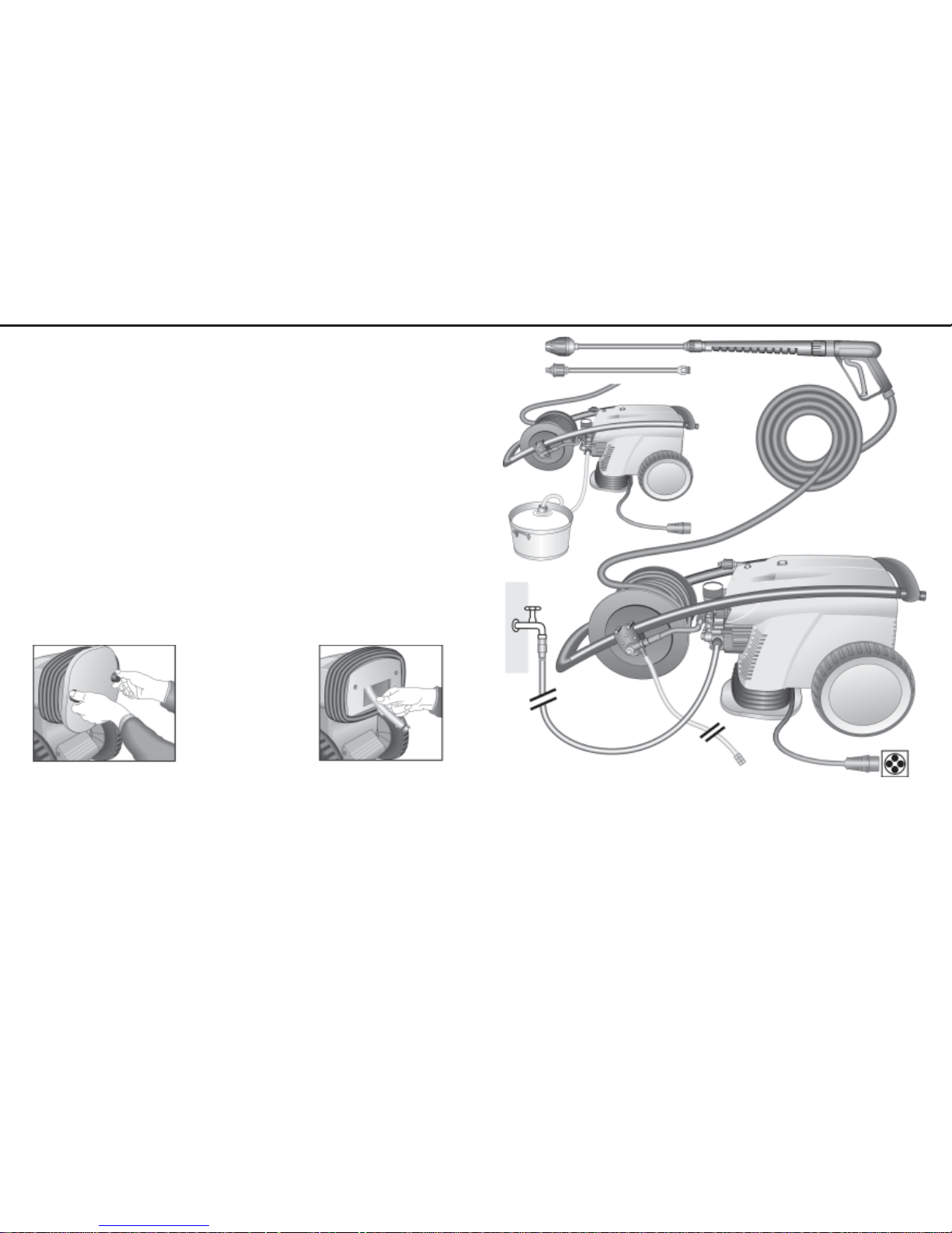
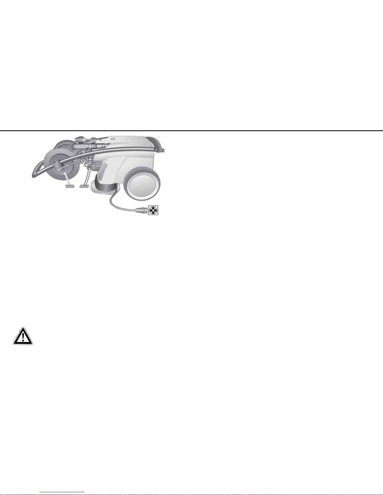
Water
1
2
3
4
5
6
7
8
9
10
11
6 High pressure injector for cleaning
agents (not with K 3170 TST)
7 High pressure hose
8 Spray gun
9 Interchangeable lance with turbokiller
10 Interch. lance with regulator nozzle
11 Pressure regulation
1 Water inlet connection with filter
2 Suction hose with filter
(Special accessory No. 15.038 3)
3 High pressure pump
4 Pressure gauge with glycerin filling
5 Unloader valve - safety valve
220 V
The KRÄNZLE 2170 TST + 3200 TST + 3250 TST + 3270 TST -
high pressure cleaners are mobile machines. The design can be seen from the diagram.
Construction
Item
DescriptionDescription
DescriptionDescription
Description
General rulesGeneral rules
General rulesGeneral rules
General rules
42 3
Page 4
The machine can only be operated when the safety trigger is squeezed.
The machine can only be operated when the safety trigger is squeezed. When the lever is
squeezed, the spray gun opens. The liquid is then pumped to the nozzle. The spray
pressure increases and quickly reaches the selected operating pressure.
When the trigger is released, the trigger gun closes and any further spraying of liquid
from the lance is stopped.
The increase in pressure when the trigger gun is closed causes the unloader valvesafety valve to open. The pump remains switched on and continues to pump liquid
through the pump at reduced pressure. When the trigger gun is opened, the unloader
valve - safety valve closes and the pump ressumes pressure spraying from the lance
The trigger gun is a safety device. Repairs should only be performed by qualified
persons. Should replacement parts be required, use only components authorized
by the manufacturer
Lance with trigger gun
The unloader valve - safety valve protects the machine from a build p of excess pressure,
and is designed not to permit an excess pressure to be selected for operation. The limit
nut on the handle is sealed with a spray coating
The operating pressure and spray rate can be steplessly adjusted by turning the handle.
Replacements, repairs, new adjustments and sealing should only be performed
by qualified persons.
Unloader valve - safety valve
Environmental, refuse disposal and water protection
regulations must be observed !
Water and Cleaning System
Water can be connected at mains pressure to the high pressure pump or it can
be sucked directly from a storage tank. The water is then forced under pressure
by the high pressure pump to the lance. The high pressure jet is formed by the
nozzle at the end of the lance.
Cleaning and caring agents can be mixed with the water by a high
pressure injector (not with K 3170 TST)
for KRÄNZLE - High Pressure Cleaners
Regular inspection every 12 months if used
professionally!
Appliance No: Type:
The following must be checked:
1. Safety features
a) Manometer
b) Safety valve (pressure control)
c) Operating pressure
d) Cut out pressure (max. 10% above
operating pressure)
e) Low pressure with trigger released
2. General condition
a) High pressure hose
b) Cable, plug, switch (VDE)
c) Spray gun
d) Motor
e) Oil level
Result of inspection: Date of inspection:
Faults rectified,
Stamp and signature
Excerpt from the Guidelines for Liquid Spray Equipment (ZH 1/46) by the Central Office of
the Professional Trade Association.
Inspection:
Liquid spray equipment should be inspected for safe operation by a qualified person
whenever necessary, but no less than every 12 months. The maker’s or supplier’s
instructions must be followed. The inspection intervals may be extended if the equipment
is not in active use.
In Germany, inspections compliant with the (German) Emission Controls Act may be
required for oil and gas-fired equipment, and the owner must arrange for these to be
carried out independently of the main inspection.
The results of inspections must be recorded in writing and presented to the respective
authorities on demand. There is no set form for these records.
The information in the operating instructions are a part of the inspection
Inspection rInspection r
Inspection rInspection r
Inspection r
eporepor
eporepor
epor
tt
tt
t
DescriptionDescription
DescriptionDescription
Description
4 41
Page 5
DescriptionDescription
DescriptionDescription
Description
40 5
With delayed motor cut-out
Frequent, work-necessitated switching on and off of motors on
machines of this size puts a heavy load on the power network
and causes increased wear on internal electrical parts. That’s
why the motor on the new KRÄNZLE switches itself off 30
seconds after the trigger is released, and switches itself back on again when the
trigger is pressed.
Safety cut-out
When running your high pressure cleaner with hot water of 80° C raised temperatures occur. Do not touch the machine without safety gloves!
CAUTION !
CAUTION !
Never use liquid containing solvents such as paint thinners, petrol, oil or similar
liquid matter. Pay attention to the instructions of the manufactur-
ers of the cleaning agents. The seals in the machine are not resistant to
solvents. The spray of solvents is inflammable, explosive and poisonous.
Setting up
Location
Neither set up and operate the machine in rooms where there is a risk of fire or
explosion nor put it into puddles. Do not use the machine under water.
If you forget to switch the machine off after use, or if the gun is not used for 20
minutes, the machine switches automatically to safety mode. It can be re-activated
by pressing the master switch.
Replacements and inspection work should only be performed by
qualified persons when the machine is disconnected from
the power supply, i.e. pull out the plug from the
electrical socket.
NotesNotes
NotesNotes
Notes
Page 6
DescriptionDescription
DescriptionDescription
Description
6 39
220 V
Electrical connection
The machine is supplied with an electrical power cord with plug.
The mains plug must be fitted to a standard grounded socket with a 30mA residual current
operated device.
The socket must be protected with a 16A delay action fuse on the mains side.
KRÄNZLE 2170 TST = 220 Volt / 60 Hz (phase-sequence
not significant
)
When using an extension cable, this must have an earthed lead which is properly
connected to the socket. The conductors in the extension cable must have a
minimum cross section of 2.5 mm². Plug connections must be of a spray-proof
design, and may not be located on a wet floor.
(with extension cables of more than 10 m - 4.0 mm2 )
CAUTION !
The use of extension cables which are too long may lead to malfunctions and
start p difficulty.
When using a cable drum, always keep the cable wound as far as possible.
NotesNotes
NotesNotes
Notes
Page 7
DescriptionDescription
DescriptionDescription
Description
38 7
Brief operating instructions
When operating your high pressure cleaner pay attention that
it is in a horizontal position.
1. Connect the high pressure hose with spray gun and machine.
2. Connect to suitable water supply.
3. Flush the air from the pump (open and close the spray gun several times)
4. Make the electrical connection - (220 Volt three-phase current).
5. Switch on the machine and commence cleaning.
6. Af ter completing the work, completely empty the pump (switch the motor on for
approximately 20 seconds without the suction and pressure hoses).
Only use clean water ! Protect from frost !
CAUTION !
Please pay attention to the regulations of your waterworks company. In accordance with
DIN 1988, the machine may not be directly connected to the public drinking water supply
lines.
A brief connection however is permissible according to DVGW (German Association for
Gas and Water Affairs) if a tube ventilator with check valve (Kränzle Order-No. 410 164) is
built into the water supply.
Also indirect connection to the public drinking water supply lines is permissible by way of
free emission in accordance with DIN 1988, part 4; e.g. by using a reservoir with a float
valve.
Direct connection to a non-drinking water supply line is permissible.
High pressure hose and spray device
The high pressure hose and spraying device supplied with the machine are made of high
grade material, they are also optimized for the machine and marked as required by the appro-
priate regulations.
If replacement parts are required, only such parts that are authorized by the
manufacturer and which bear the markings required by the appropriate regulations may be used. The high pressure hose and spray device must be connected in a pressure-tight manner. The high pressure hose may not be driven
over, pulled excessively, or twisted. The hose may under no circumstances be
pulled over sharp edges, since otherwise the guarantee is automatically void.
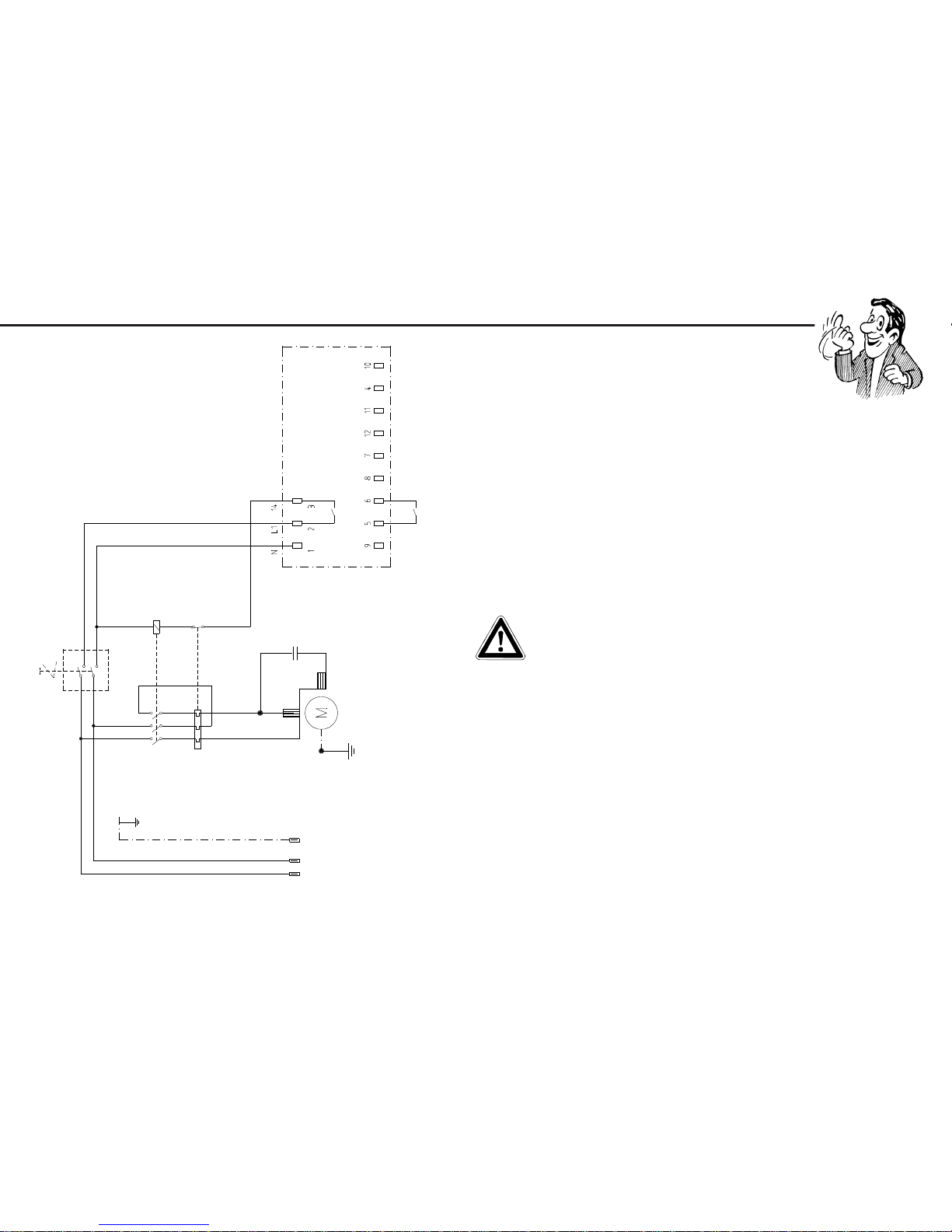
Wiring diagramWiring diagram
Wiring diagramWiring diagram
Wiring diagram
On-Off switch
Inlet line via
CEE 3 x 2,5mm²
220 V / 60 Hz
Motor
230 V / 60 Hz
Pressure switch
Control plate with
Trafo 230 V / 50/60 Hz
overload
protection
23-32 Ampere
Page 8

Safety notesSafety notes
Safety notesSafety notes
Safety notes
8 37
As to the recoil
- see notice on
page 2 !
Apply the safety catch on the
spray gun after each use, in order to prevent unintentional
spraying!
Always aim the underbody
lance. Note when using an
angled underbody lance,
like for example lance No.
41.075, that there is a certain amount of torque in
the recoil.
(See also notice on page 2)
StandarStandar
StandarStandar
Standar
d Vd V
d Vd V
d V
ario-Jet Nozzleario-Jet Nozzle
ario-Jet Nozzleario-Jet Nozzle
ario-Jet Nozzle
No Description Qty. Ord.-No
30 Nippel ST30 M22x1,5 AG / M 12 x 1 1 13.363
31 Rohr 400 mm, bds. M 12 x 1 1 15.002
32 Regeldüse mit Regulierring 1 13.201 2
33 Flachstrahldüse 1 26.001
Please specify size of nozzle
25045 with K 2170
Spare parts list KRÄNZLE 3200 TST - 3270 TST
Standard vario-jet nozzle
Page 9

This is what you’ve purThis is what you’ve pur
This is what you’ve purThis is what you’ve pur
This is what you’ve pur
chased:chased:
chased:chased:
chased:
36 9
1. Turbokiller
Spray lance with regulator and
high pressure nozzle,
flat spray
25°
2. Spray gun with insulated pistol
grip and screw connection and
pressure regulation.
3. KRÄNZLE - high pressure cleaners
2170 TST, 3200 TST, 3250 TST, 3270 TST
4. Operating instructions
5. High pressure hose, 20 m NW 8
on hose drum
Turbokiller
No Description Qty. Ord.-No
111 Sprühkörperschutz 1 41.528
12 Sprühkörper 1 41.529
13 O-Ring 6,88 x 1,68 1 41.521
14 Düsensitz 1 41.522
15 Düse 045 für K 2170 TST 1 41.532 1
16 Ring 1 41.533
17 Rotor 1 41.534
18 Stabilisator 1 41.524
19 O-Ring 41 x 1,78 1 41.538
20 Deckel 1 41.539
21 Deckelschutz 1 41.540
22 Rohr 500 mm lang; bds. R1/4" 1 12.385 1
23 Nippel M22x1,5 x R1/4" IG 1 13.370
Turbokiller 045 compl. with lance 41.072 3
Spare parts list KRÄNZLE 3170 TST - 3270 TST
Turbokiller
Page 10

How to assemble and furnish your high pressure cleaner
10 35
To put the high pressure cleaner into the mobile position,
press 1) your foot against the tilt support, and 2) pull the
machine towards you.
Now you can
move the
machine
Drum for
HPhose
Tubular holder
for gun
Suction pipe for
additives
Tubular holder for turboKiller and lance
Cable
First set up the machine. Then take off the crank and fit it on the side. Fasten it with
the splint.
To check the oil level, unscrew the oil screw and
check the dip-stick.
K 3170 TST - K 3270 TST
Spare parts list KRÄNZLE 2170 TST - 3270 TST
Hose drum
No Description Qty. Ord.-No
1 Seitenschale Schlauchführung 1 40.302
2 Seitenschale Wasserführung 1 40.301
3 Trommel Unterteil 1 40.304
4 Trommel Oberteil 1 40.303
5 Innensechskantschraube M 4 x 25 4 40.313
6 Lagerklotz mit Bremse 1 40.306
7 Lagerklotz links 1 40.305
8 Klemmstück 2 40.307
9 Kunststoffschraube 5,0 x 20 12 43.018
10 Antriebswelle 1 40.310
1 1 Welle Wasserführung 1 40.31 1
12 Elastic-Stop-Mutter M 4 4 40.111
13 Handkurbel 1 40.309
14 Verriegelungsbolzen 1 40.312
15 Scheibe MS 16 x 24 x 2 1 40.181
16 Wellensicherungsring 22 mm 2 40.117
17 Wellensicherungsring 16 mm 1 40.182
No Description Qty. Ord.-No
20 Parbaks 16 mm 2 13.159
21 Sicherungsscheibe 6 DIN6799 1 40.315
23 Drehgelenk 1 40.167
24 Eingangsinjektor 1 40.317
25 Distanzring 1 40.316
27 O-Ring 6,68 x 1,78 1 40.585
28 O-Ring 10 x 2 1 43.068
45 Hochdruckschlauch 20 m NW 8 1 41.083
42 O-Ring 9,3 x 2,4 (Viton) 2 13.273 1
No. 31-34 only for K3200 - 3270 TST
31 Edelstahlfeder 1 13.239
32 Edelstahlkugel 5,5 1 13.238
33 Saugzapfen Schlauchanschluß 1 13.236
34 Chemikaliensaugschlauch mit Filter 1 15.038
No. 31.1 + 33.1 only for K3170 TST
31.1 O-Ring 6 x 1,5 1 13.386
33.1 Stopfen M 10 x 1 1 13.385
Page 11

PrPr
PrPr
Pr
eparation for useeparation for use
eparation for useeparation for use
eparation for use
34 11
1. Put high pressure cleaner into horizontal position!
THE HIGH PRESSURE CLEANER IS ONLY TO BE
OPERATED IN HORIZONTAL POSITION !
For operation in vertical position
contact manifacturer first !
2. Connect the high pressure lance or Turbokiller
to the spray gun.
Unwind from
drum!
Connect high pressure hose to
the spray gun.
Hose drumHose drum
Hose drumHose drum
Hose drum
Page 12

PrPr
PrPr
Pr
eparation for useeparation for use
eparation for useeparation for use
eparation for use
12 33
4. The machine can be connected to a
pressurised water line with cold or 80°C hot
water (see page 2).
Ensure that the water supply is clean when
sucking from external sources. The hose
cross section must be at least 3/4” =
16 mm (free passage).
Filter 1 must always be
clean.
Please make sure that
the filter is clean before
using your high pressure
cleaner.
CAUTION !
When running your high pressure cleaner with hot water of 80 °C raised temperatures occur.
Do not touch the pump without safety gloves!
5. Maximum induction height 2.5 m
see technical data on page 2
Maximum temperature of
the inducted water: 60°C
Water
K 3170 TST - K 3270 TST
No Description Qty. Ord.-No
1 Ölgehäuse 1 40.501
4 Innensechskantschraube M 8 x 25 6 40.053
5 Sicherungsscheibe 6 40.054
6 Flachdichtung 1 40.511
7 Öldichtung 20 x 30x 7 3 40.044 1
8 Wellenscheibe 1 40.043
9 Axial-Rollenkäfig 1 40.040
10 AS-Scheibe 1 40.041
11.1 Taumelscheibe AQ 7,0° bei K 2170 TST 1 40.042 1
please specify angle 7,0° when ordering
12 Plungerfeder 3 40.506
13 Federdruckscheibe 3 40.510
14 Plunger 20 mm (lang) 3 40.505
15 Sprengring 3 40.048
16 O-Ring 14 x 2 2 43.445
17 Stopfen M 18 x 1,5 1 41.011
18 Flachdichtung 1 41.019 3
19 Deckel 1 40.518
20 Innensechskantschraube M 5 x 12 4 41.019 4
21 Stopfen M 18 x 1,5 mit Ölmeßstab 1 42.520
22 Stützscheibe für Plungerfeder 3 40.513
23 Ölablasschlauch 1 42.521 1
24 Kupferring 3 14.149
25 Verschlußkappe 1 44.130
Spare parts list KRÄNZLE 3170 TST - 3270 TST
Transmission unit for AQ-Pump
Page 13

PrPr
PrPr
Pr
eparation for useeparation for use
eparation for useeparation for use
eparation for use
32 13
When using cleansing agents:
Place chemical filter no. 5 in the reservoir with the cleansing agent. Turn on Vario-Jet No.4 to
to enable the injector to induct the cleansing agent. By turning back the Vario-Jet nozzle, the
supply of chemical is automatically cut off. Allow the cleansing agent to take effect and then
remove with high pressure spray.
A mixing ratio of 3-5% is achieved
when the Vario-Jet is fully turned
on. pH value neutral 7-9.
Note that you must always
comply with the instructions
provided by the manufacturer of the cleansing agent
(e.g. instructions concerning safety clothing) and the
water protection regulations!
1. Switch off the machine.
2. Cut off the water supply.
3. Open the spray gun briefly until the pressure is released.
4. Apply the safety catch on the spray gun.
5. Remove the water hose and spray gun.
6. Drain the pump: switch on the motor for approx. 20 seconds.
7. Pull the plug from the socket.
8. Winter: store the pump in rooms above 0 °C.
9. Clean the water filter.
To shut down the pump:
TT
TT
T
ransmission unitransmission unit
ransmission unitransmission unit
ransmission unit
Page 14

PrPr
PrPr
Pr
eparation for useeparation for use
eparation for useeparation for use
eparation for use
14 31
Adjusting the pressure at the gun
Simply turn the adjustment ring.
The machine is set to operate at maximum pressure.
Adjusting the pressure at the handwheel
Turn the handwheel at the side.
The machine is set to operate at maximum pressure.
K 3170 TST - K 3270 TSTK 3170 TST - K 3270 TST
K 3170 TST - K 3270 TSTK 3170 TST - K 3270 TST
K 3170 TST - K 3270 TST
Spare parts list KRÄNZLE 3170 TST - 3270 TST
Valve housing for integrated AQ-pump
No Description Qty. Ord.-No
1 Ventilgehäuse AQ mit integr. UL und 1 40.503
Druckschalter
2 O-Ring 18 x 2 6 40.016
3 Einlaß- / Auslaß- Ventil 6 42.024
4 O-Ring 21 x 2 6 42.025
5 Ventilstopfen 5 42.026
5.1 Ventilstopfen mit R 1/4" IG 1 42.026 2
6 Sicherungsring 4 40.032
7 Innensechskantschraube M 12 x 45 4 40.504
8 Sauganschluß R 1/2" AG 1 41.016 1
9 Wassereingangsfilter 1 41.046 2
13 Gewebemanschette 3 40.023
14 Backring 20 mm 6 40.025
15 O-Ring 31,42 x 2,62 3 40.508
16 Leckagering 20 x 36 x 13,3 3 40.509
17 Cu-Dichtring 21 x 28 x 1,5 1 42.039
18 Gummimanschette 3 40.512
19 Verschlußschraube R 1/2" 1 42.032
20 Distanzring mit Abstützung 3 40.507
23 Druckring 20 mm 3 40.021
24 Zwischenring 20 mm 3 40.516
25 Rückschlagkörper 1 14.122
26 O-Ring 6 x 3 1 14.121
No Description Qty. Ord.-No
28 Verschraubung Ermeto R 1/4" x 8L 1 41.042
29 Dichtring 17 x 22 x 1,5 (Kupfer) 1 40.019
30 Stopfen 3/8" 1 40.018
31 Dichtstopfen M 10 x 1 1 43.043
32 Dichtstopfen M 8 x 1 2 13.158
33 Ausgangsteil 1 42.161
34 Rückschlagfeder 1 14.120
37 O-Ring 18 x 2 1 43.446
48 O-Ring 1 13.272
49 Schlauchtülle 1 44.126 1
50 Überwurfmutter 1 44.122
51 Schlauchschelle 1 44.054 1
Repair kits:
Repair kit for sleeves 40.065 1
consisting of: 3x No. 13; 6x No. 14;
3x No. 15; 3x No 16; 3x No. 18;
3x No 20; 3x No. 23
Repair kit for sleeves without 40.517
brass parts consisting of:
3x No. 13; 6x No. 14; 3x No. 15;
3x No. 18; 3x No. 23
Repair kit valves 40.062 1
consisting of:
6x No. 2; 6x No. 3; 6x No. 4
Page 15

30 15
This is prThis is pr
This is prThis is pr
This is pr
ohibited !ohibited !
ohibited !ohibited !
ohibited !
Never allow
children to use the
high pressure
cleaner !
Never direct the
water jet at the
machine itself !
Never direct the
water jet at a
power socket !
VV
VV
V
alve housingalve housing
alve housingalve housing
alve housing
Page 16

This is prThis is pr
This is prThis is pr
This is pr
ohibited !ohibited !
ohibited !ohibited !
ohibited !
16 29
Do not damage the
power cord or repair
it incorrectly !
Never direct the
water jet at people
or animals !
Never pull the high
pressure hose if it
has formed kinks
or “nooses”!
Never pull the hose
over sharp edges !
K 3170 TST - K 3270 TST
Spare parts list KRÄNZLE 3170 TST - 3270 TST
Unloader valve and pressure switch
No Description Qty. Ord.-No
5 O-Ring 16 x 2 2 13.150
8 O-Ring 11 x 1,44 1 12.256
9 Edelstahlsitz 1 14.118
10 Sicherungsring 1 13.147
11 Edelstahlkugel 1 13.148
12 Edelstahlfeder 1 14.119
13 Verschlußschraube 1 14.113
14 Steuerkolben 1 14.134
15 Parbaks 16 mm 1 13.159
16 Parbaks 8 mm 1 14.123
17 Spanstift 1 14.148
18 Kolbenführung spezial 1 42.105
19 Kontermutter M 8 x 1 2 14.144
20 Ventilfeder schwarz 1 14.125
21 Federdruckscheibe 1 14.126
22 Nadellager 1 14.146
23 Handrad 1 14.147
25 Elastic-Stop-Mutter M 8 x 1 1 14.152
26 Manometer 0-400 Bar 1 15.039 4
27 Aluminium-Dichtring 2 13.275
51 Führungsteil Steuerstößel 1 15.009 1
52 O-Ring 12,3 x 2,4 1 15.017
53 O-Ring 14 x 2 1 43.445
54 O-Ring 3,3 x 2,4 3 12.136
No Description Qty. Ord.-No
55 Stützscheibe 2 15.015
56 Edelstahlfeder 1 15.016
57 Steuerstößel 1 15.010 2
58 Parbaks 1 15.013
59 Stopfen M 10 x 1 (durchgebohrt) 1 13.385 1
60 Gehäuse Elektroschalter 1 15.007
61 Gummimanschette PG 9 1 15.020
62 Scheibe PG 9 1 15.021
63 Verschraubung PG 9 1 15.022
64 PVC-Kabel 2x 1,0 mm² 1 42.505
65 Blechschruabe 2,8 x 16 6 15.024
66 Deckel Elektroschalter 1 15.008
67 O-Ring 44 x 2,5 1 15.023
68 Mikroschalter 1 15.018
69 Zylinderschraube M 4 x 20 2 15.025
70 Sechskant - Mutter M 4 2 15.026
72 Druckfeder 1 x 8,6 x 30 1 40.520
Repair kits:
Repair kit for pressure switch 15.009 3
1x No. 51, 1x No. 52, 1x No. 53,
3x No. 54, 1x No. 55, 1x No. 56,
1x No. 57, 1x No. 58, 1x No. 59
Pressure switch compl. No. 54 - 70 41.300 5
Page 17

Additional KRÄNZLE-accessories for ...Additional KRÄNZLE-accessories for ...
Additional KRÄNZLE-accessories for ...Additional KRÄNZLE-accessories for ...
Additional KRÄNZLE-accessories for ...
(on demand)(on demand)
(on demand)(on demand)
(on demand)
28 17
Rotary scrubbing brush
Order No. 41.050 1
Drain and pipe cleaning
hose
8 m - Order No. 41.051
15 m - Order No. 41.058
Underbody lance
Order No. 41.075
Environmental, refuse disposal and water protection
regulations must be observed when using the accessories!
Unloader valve and prUnloader valve and pr
Unloader valve and prUnloader valve and pr
Unloader valve and pr
essuressur
essuressur
essur
e switche switch
e switche switch
e switch
Page 18

... fur... fur
... fur... fur
... fur
ther combination possibilitiesther combination possibilities
ther combination possibilitiesther combination possibilities
ther combination possibilities
18 27
Car cleaning, glass, caravan, boat etc.:
rotary washing brush with 40 cm extension and ST 30 nipple M22 x 1,5
Cleaning pipes, channels and drains:
pipe cleaning hose with KN nozzle and
ST 30 nipple M22 x 1,5
Underbody cleaning of cars, trailers and
equipment:
lance 90 cm with high pressure nozzle and
ST 30 nipple M 22 x 1,5.
The lance must be aimed when spraying
Rotary point sprayer for extreme
soiling:
Turbokiller with 40 cm extension and
ST 30 nipple M22 x 1,5
Cleaning cars and all smooth surfaces:
brush with ST 30 nipple M22 x 1,5
K 3170 TST - K 3270 TSTK 3170 TST - K 3270 TST
K 3170 TST - K 3270 TSTK 3170 TST - K 3270 TST
K 3170 TST - K 3270 TST
No Description Qty. Ord.-No
1 Stator 112 4,0kW 220V / 60Hz 1 40.541 1
2 A-Lager Flansch 1 40.530
3 Rotor 112 (400V / 50Hz) 1 40.531 1
4 Lüfterrad für BG 112 1 40.532
5 Lüfterhaube BG 112 1 40.533
7 Flachdichtung 1 43.030
10 Kegelrollenlager 31306 1 40.103
11 Öldichtung 35 x 47 x 7 1 40.080
12 Paßfeder 8 x 7 x 32 1 40.104
13 Kugellager 6206 - 2Z 1 40.538
14 Innensechskantschraube M 6 x 30 4 43.037
15 Federausgleichsscheibe 1 40.537
17 Vierkantmutter M 5 2 41.416
18 Schraube M 5 x 14 2 40.536
19 Schraube M 4 x 12 4 41.489
20 Schelle für Lüfterrad 112 2 40.535
21 Schraube M 4 x 12 4 41.489
22 Erdungsschraube kpl. 1 43.038
23 Schalter 14,5A Amazonas 1 41.111 6
24 Kunststoffschraube 4,0 x 16 6 43.417
25 Bock für Schalter 1 42.522
26 Kunststoffschraube 5,0 x 25 6 41.414
28 Kuststoffschraube 3,5 x 20 2 43.415
29 Lüsterklemme 5-pol. 1 43.326 1
30 Schütz CA3-23-10 220-230V 50/60 Hz 1 44.057 2
31 Schaltkasten Unterteil 1 42.523
32 Schaltkasten Deckel 1 42.524
33 Steuerplatine Abschaltverz. 230V / 50Hz 1 42.504
34 Klemmrahmen mit Schalterabdichtung 1 43.453
36 Blechschraube 3,5 x 16 2 44.161
37 PG 16-Verschraubung 1 41.419 1
38 Dichtung für Schaltkastendeckel 1 42.525
39 Gegenmutter für PG9-Verschraubung 1 41.087 1
40 Gegenmutter für PG16-Verschraubung 1 44.119
41 PG 9 - Verschraubung 1 43.034
42 Überstromauslöser CT 3-32-32A 1 44.058 4
Spare parts list KRÄNZLE 3170 TST - 3270 TST
Motor
Page 19

MotorMotor
MotorMotor
Motor
Small rSmall r
Small rSmall r
Small r
epairs - Do it yourself!epairs - Do it yourself!
epairs - Do it yourself!epairs - Do it yourself!
epairs - Do it yourself!
26 19
The pressure gauge shows a 10% higher pressure than the working
pressure.
Only K3200 - K3270 TST
You only get a weak flow of water or no water at all!
The injector may
be dirty and you
should first
remove the
hose!
then straighten
a paper clip...
...release the
injector with
an open-
ended
spanner...
... and
remove the
injector.
Clean the injector
thoroughly from both
sides ...
... and check
that it is clean.
Reconnect the
hose
and you are
ready to
continue your
work.
Now turn on the water
and you should get a
powerful stream of water
but if you only get a
weak flow
Verschrauben
Sie dann
wieder
Injektor und
Zuleitung.
Page 20

Small rSmall r
Small rSmall r
Small r
epairs ...epairs ...
epairs ...epairs ...
epairs ...
20 25
The nozzle is blocked!
No water but the gauge shows full pressure !
Rinse the hose through
first.
You should now have
a powerful stream
of water,
but if you
only get a few
drops of water
from the
lance
remove the lance and clean
the nozzle.
Using the flat spray lance
you only have to clean the
front nozzle.
Straighten a paper
clip and clean the
nozzle.
Insert pointed object
into the hole and pull
the cap back!
Check visually whether the
nozzle is clean.
Now it works as well
as before.
K 3170 TST - K 3270 TSTK 3170 TST - K 3270 TST
K 3170 TST - K 3270 TSTK 3170 TST - K 3270 TST
K 3170 TST - K 3270 TST
Spare parts list KRÄNZLE 3170 TST - 3270 TST
Complete Assembly
No Description Qty. Ord.-No
2 Griff 2 42.508
3 Griffschraube 4 42.509
4 Gummipuffer 25 x 25 2 41.513
5 Gehäusehälfte rechts 1 42.511
6 Gehäusehälfte links 1 42.512
7 Kabeldurchführung 1 42.513
8 Zugentlastung 1 43.431
9 Blechschraube 3,5 x 12 2 40.290
10 Kunststoffschraube 5,0 x 25 13 41.414
11 Kunststoffschraube 5,0 x 14 10 43.426
12 Blechmutter 6 42.506
13 Deckel 1 1 42.514
14 Deckel 2 1 42.515
15 Gummipuffer 30 x 20 2 42.516
16 Rad 2 44.017
17 Starlockkappe 20 mm 2 40.142
18 Radkappe 2 44.018
19 Frontplatte K 2170 TST 1 42.517 5
No Description Qty. Ord.-No
20 Köcher groß 5 42.518
21 Köcher klein 1 42.519
22 Fahrgestell 1 42.507
23 Schloßschraube M 8 x 40 4 41.703
24 Elastic-Stop-Mutter M8 4 41.410
25 Netzanschlußkabel 8 m 1 44.036 1
26 Schlauchtrommel kpl. mit Chemieans. 1 41.259 4
für K 2170 TST
27 Chemiesaugschlauch (Gewebe) mit Filter 1 44.056
28 Starlet II 1 12.320 2
29 Lanze mit Flachstrahldüse 1 41.043 2
bitte Düsengröße mit angeben 1
25045 bei K2170 TST
30 Turbo-Killer 045 bei K3270 1 41.072 3
31 Hochdruckschlauch 20 m NW8 1 41.083
32 Hochdruckschlauch 1 42.536
Page 21

24 21
do it yourself !do it yourself !
do it yourself !do it yourself !
do it yourself !
Nozzle dirty or sticky
Pressure gauge does not show full pressure
Water comes out in spurts.
If you do not use the high-pressure cleaner for some time the valves can stick
The high-pressure hose vibrates
Straighten a
paper clip...
When a valve is
blocked,
the gauge
shows little
pressure or
no pressure
at all,
or the high
pressure
hose
vibrates!
Open the
valve with a
socket wrench...
and remove the
valve screw, the
valve and the
o-ring.
Replace the rubber o-ring.
and remove the
dirt from the
valve - the valve
inside must be
closed.
Retighten the valve
screw
...and repeat
on all 6
valves.
Now it works
as well as
before!
Complete AssemblyComplete Assembly
Complete AssemblyComplete Assembly
Complete Assembly
Page 22

22 23
Starlet II with lanceStarlet II with lance
Starlet II with lanceStarlet II with lance
Starlet II with lance
K 3170 TST - K 3270 TSTK 3170 TST - K 3270 TST
K 3170 TST - K 3270 TSTK 3170 TST - K 3270 TST
K 3170 TST - K 3270 TST
Spare parts list KRÄNZLE 3170 TST - 3270 TST
Starlet II with lance
No Description Qty. Ord.-No
1 Ventilkörper kunststoffumspritzt 1 12.294
2 Schutzhülse 1 12.295
3 Abdeckschutz 1 12.296
4 Betätigungshebel 1 12.298
5 Sicherungshebel 1 12.149
6 Abschlußschraube M 16 x 1 1 12.247
7 Stopfen 1 12.287
8 Gewindeführungshülse R 1/4" AG 1 12.250
9 Aufsteuerbolzen 1 12.284
10 Stift 1 12.148
11 Lagernadel 1 12.253
12 Edelstahlfeder 1 12.246
13 Edelstahlkugel 1 12.245
14 Edelstahlsitz 1 13.146
15 O-Ring 11 x 1,44 1 12.256
16 O-Ring 3,3 x 2,4 1 12.136
17 Blechschraube 3,9 x 8 4 12.297
18 Druckstück 1 12.252
19 Rohr kunststoffumspritzt 1
20 Überwurfmutter ST30 M22x1,5 1 13.276 1
No Description Qty. Ord.-No
21 Außensechskantnippel R 1/4" IG 1 13.277 1
22 O-Ring 9,3 x 2,4 Viton 1 13.273 1
23 Alu-Dichtring 4 13.275
24 O-Ring 15 x 1,5 1 12.129 1
25 Sicherungsring 1 12.258
51 Düsenschutz 1 26.002
52 Rohr 396 mm; bds. R1/4" 1 12.385
53 ST 30 Nippel M 22 x 1,5 / R1/4" m. ISK 1 13.370
54 Flachstrahldüse 1 D25045
Rep.-Satz "Starlet II" 12.299
bestehend aus je 1x Position:
9; 13; 14; 15; 16; 25
 Loading...