

Kranzle 11/130, 12/150, 15/120, therm CA 11/130, therm CA 12/150 Operating Maintenance Installation
Page 1

Hot Water-High Pressure Cleaners
Operating manual
Read and confor m to
safety instructions
before use
GB
11/130
12/150
15/120
Page 2

Dear Customer
We would like to congratulate you on your new hot water high pressure cleaner, and
to thank you for buying it!
The following pages contain information about the machine in order to familiarize
you with it and facilitate its use.
The machine is a professional cleaning aid in all cleaning tasks, e.g.:
Description
2
*1
therm CA 11/130
30 - 130 bar
25045
145 bar
max. 660 l/h
12 - 80 °C
max. 140 °C
1.35 Gph/10bar
4.8 kg/h (=5.7 l/h)
49 kW
0.032 kg/s
25 l
10 m
15 m
230V / 50Hz / 15A
P1: 3.4 kW
P2: 2.3 kW
150 kg
790 x 590 x 980
83 dB (A)
90 dB (A)
2.1 m/s²
approx. 20 N
Permissible tolerance for figures ± 5 % in acc. with VDMA uniform sheet 24411
*1
Min. water quantity to be supplied to the high pressure cleaner!
therm CA 12/150
30 - 150 bar
25045
170 bar
max. 720 l/h
12 - 80 °C
max. 140 °C
1.35 Gph/11bar
5,3 kg/h (=6,3 l/h)
55 kW
0.035 kg/s
25 l
10 m
15 m
400V / 50Hz / 6.5A
P1: 4.0 kW
P2: 2.7 kW
150 kg
790 x 590 x 980
89 dB (A)
92 dB (A)
2.1 m/s²
approx. 22 N
- facades
- flagstones
- removing of old paint etc.
- vehicles of all types
- sheds
- machines
- containers
e.g.: food processing
industry
Technical data
Operating pressure
Nozzle size
Permissible overpressure
Water output
Hot water output
Steam level
Heat.oil nozzle/Heat.oil press.
Heat. oil consumpt. (Heat. oil EL)
Heating capacity
Exhaust gas mass flow
Fuel tank
High pressure hose
with hose drum
Electrical rating:
Input
Output
Weight
Dimens. in mm without reel
Sound level acc. to DIN 45 635
Guaranteed sound level L
WA
Vibrations at lance
Recoil at lance
therm CA 15/120
30 - 120 bar
25070
135 bar
max. 900 l/h
12 - 80 °C
max. 140 °C
1,5 Gph/10bar
5,8 kg/h (=6,8 l/h)
60 kW
0,037 kg/s
25 l
10 m
15 m
400V / 50Hz / 7,5A
P1: 4,0 kW
P2: 2,7 kW
150 kg
790 x 590 x 980
89 dB (A)
92 dB (A)
2,2 m/s²
approx. 24 N
Page 3
3
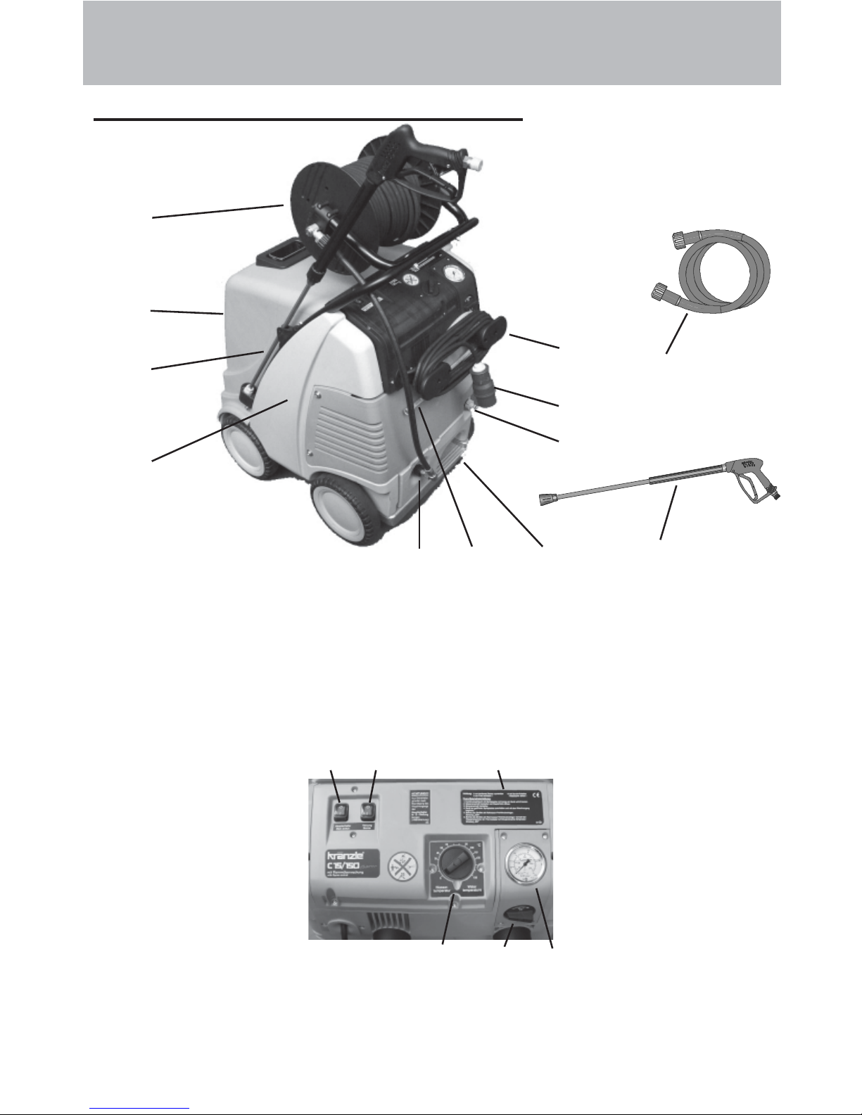
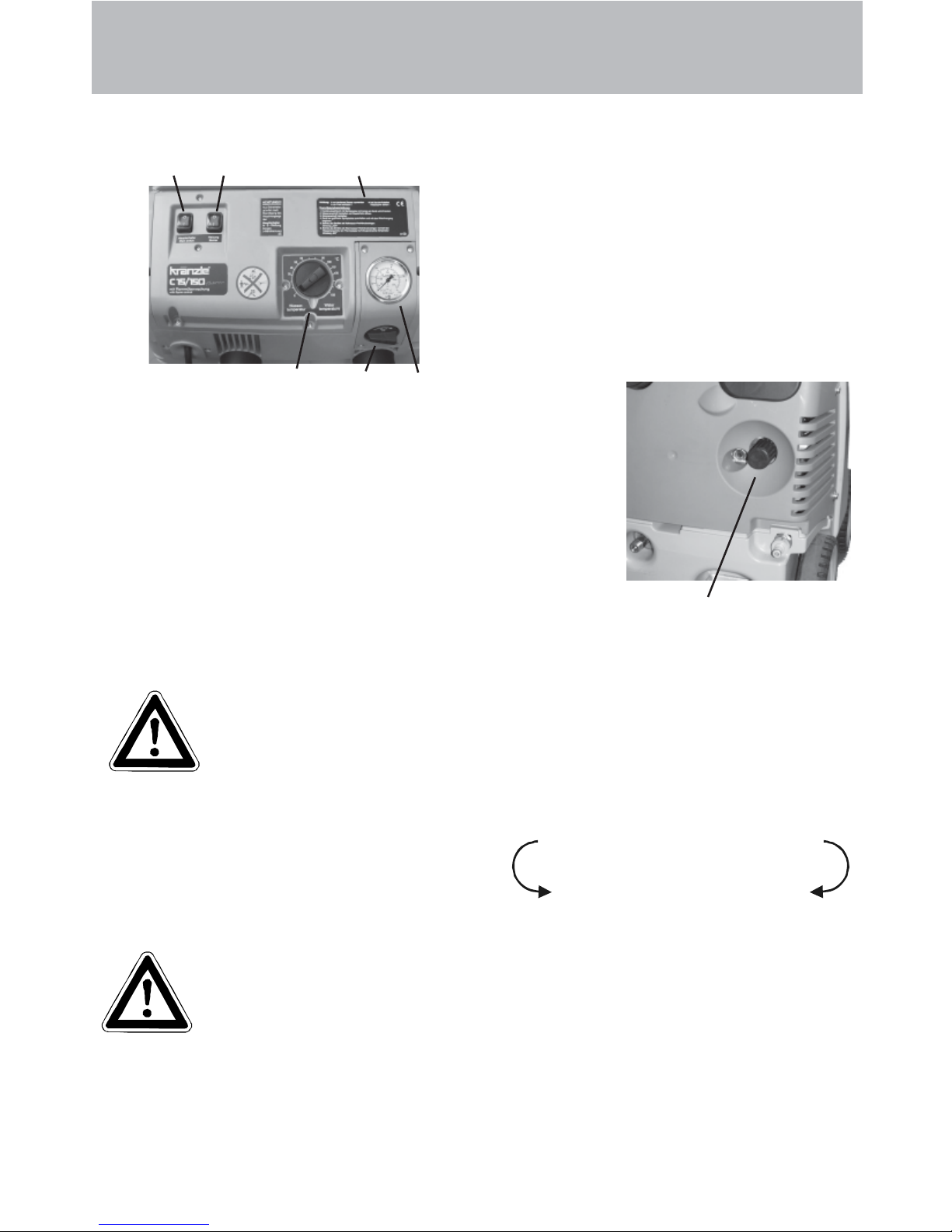
Connections and functional parts
8
10
1
5
94
6
15 16 17
2019
Description
2
3
11
12
13
18
8 Storage bin for spray gun and pipe
9 Brake
1 0 Fuel tank
1 1 Filler aperture for fuel
12 High pressure outlet
13 Hose drum (special accessories)
1 Water inlet connection with filter
2 Power cable
3 Winder for cable
4 Suction hose for detergent
5 High pressure hose
6 Spray gun
7 Spray pipe attachment
1 5 Master switch (appliance On- Off)
1 6 (Burner ON- OFF) ignition
17 Brief operating instructions
18 Manometer
19 Thermostat
20 Detergent dispensing valve
Page 4
Motor protection switch
The pump motor is protected from overload by a motor protecting switch. In case of
an overload the motor is switched off by this motor protecting switch. For a restart
the master switch has to be switched off and then on again. In case of a repeated
switching off of the motor by the motor protecting switch the cause of the
malfunction has to be removed.
Replacement and inspection work may
only be performed by trained personnel.
4
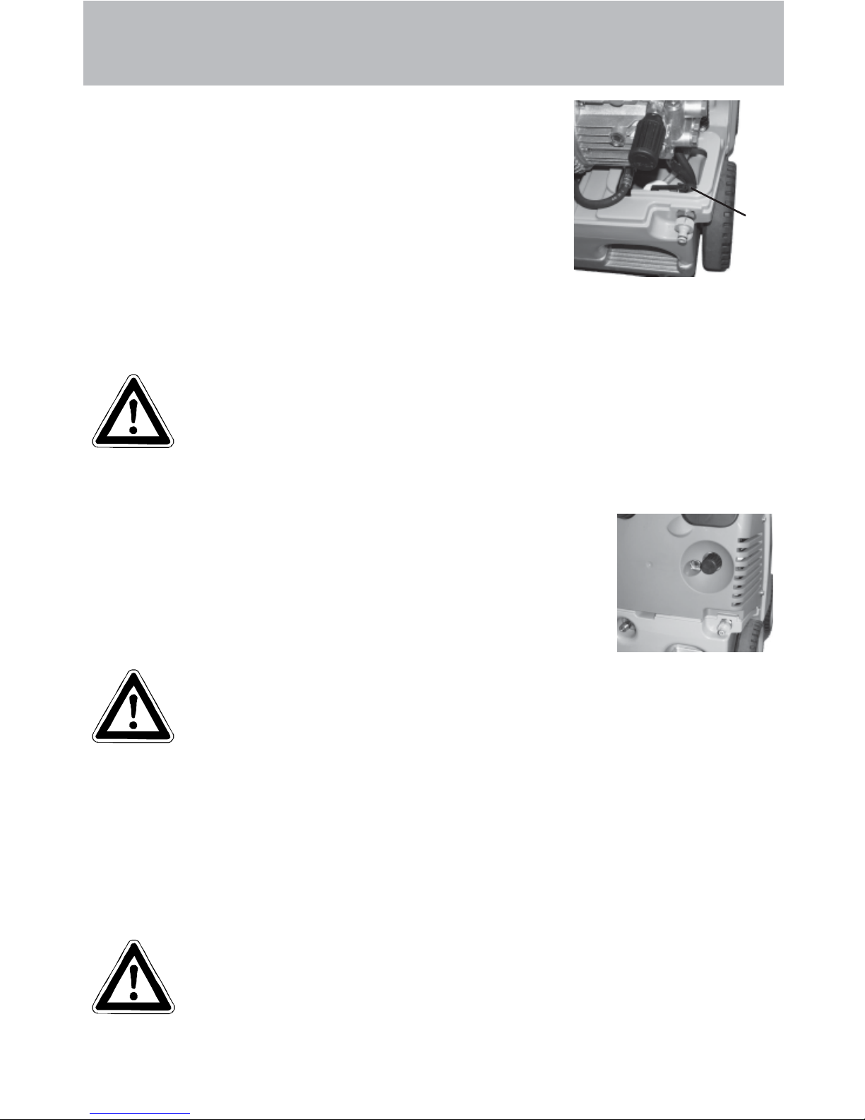
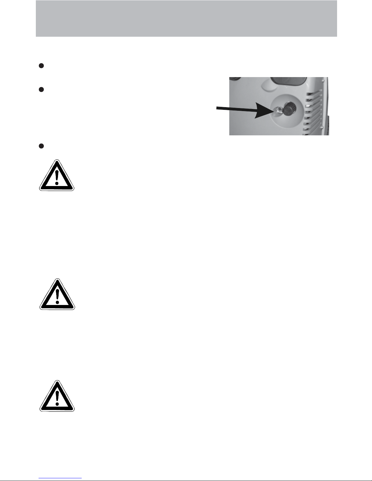
Water system
The water flows into a tank.
A float valve (a) regulates the water intake.
The water is then directed to the safety spray pipe under
pressure from the high pressure pump.
The high pressure spray is formed through the nozzle on
the spray pipe.
Detergent and caring system
The high pressure pump can also suck a detergent/caring agent and mix it with the
high pressure jet. - The detergent must have the ph-value 7-9 neutral.
Only open the dosing valve, if the chemistry sieve is placed in a
liquid.
The rules concerning the environment, refuse and ground water
protection must be complied with!
Pressure control and safety facilities
The pressure control valve allows full adjustment of the
quantity and pressure of the water.
The safety valve protects the machine from excessive
pressure and cannot be adjusted beyond the admissible
operating pressure. The setting nuts are sealed with lacquer .
Replacements, repairs, new adjustments and sealing operations
may only be performed by trained personnel.
Description
a
Page 5
1
Description
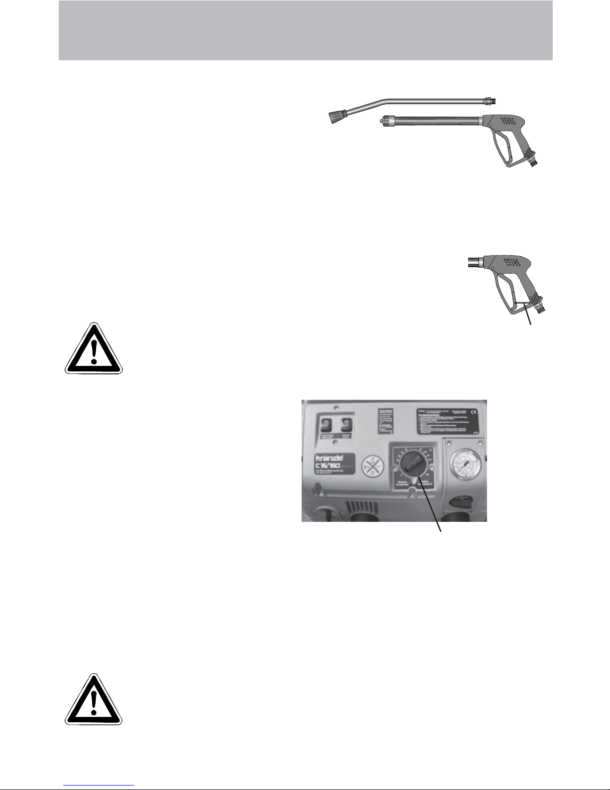
Spray pipe with spray gun
The spray gun only allows the machine to
be operated when the safety trigger is
pulled.
The spray gun can be used when the safety
trigger is pulled. The machine is started and
the liquid transported to the nozzle. Spray
pressure builds up and quickly reaches the selected operating pressure.
When the trigger is released the gun is closed, which prevents any further liquid
from coming out of the spray pipe and the motor is stopped.
After completing work with your Kränzle therm CA, or if work is
interrupted, the safety catch (1) must be applied. This makes it
impossible to press the trigger by accident.
The spray gun is a safety device. Repairs may only
be performed by trained personnel. If spare parts
are required, use only those approved by the maker.
5
Thermostat
The thermostat with rotary control
switch controls the temperature
of the spray water .
Use the rotary control switch to adjust
the desired water temperature.
Thermostat with rotary
control switch
High pressure hose and spray equipment
The high pressure hose and spray equipment supplied with the machine are made
of high quality material specially adapted for the operating conditions of the
machine, and are properly marked.
If spare parts are required, only properly marked components
approved by the maker should be used. High pressure hoses and
spray equipment must be connected so that they are pressuretight. The high pressure hoses should not be driven over , pulled
excessively or twisted. Do not pull the hose over sharp edges,
since this will invalidate the warranty.
Page 6
4
5
3
2
10
7
6
8
11
9
1
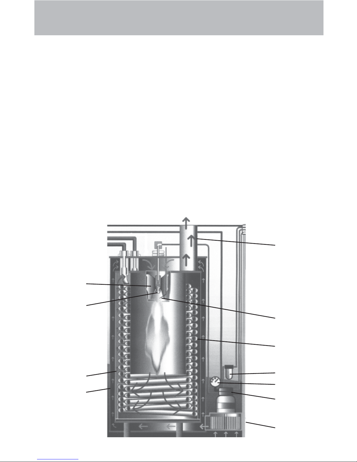
Heat exchanger
Heating coil: 34 m long - Content: 5 l of water – Heating capacity: 70 k W
The heat exchanger is heated by a high pressure fan heater .
A ventilator (1) draws in the cold, fresh air from the bottom end of the machine and
forces it upwards between the outer mantle (2) and the inner mantle (3). In the process,
the fresh air is pre-heated and the outer mantle of the heat exchanger is cooled.
The pre-heated air is pressed through a mixing unit (4). Here finely atomized fuel is
injected via a nozzle (5) and mixed with the air . The electrodes (6) located below then
ignite the fuel-air mixture.
The flame burns from top to bottom, turns round and the hot gas flows past the heating
coil (7) on its way back up. The burned gases collect in the exhaust chamber and are
emitted from the chimney (8).
The water is forced through a heating coil by the high pressure pump. Hot air flows
around the coil, as described above.
The fuel pump (9) draws the oil through a filter (10) and pumps it to the injector nozzle
(5). The surplus quantity of fuel flows straight back into the tank. The oil pressure is
shown on the fuel manometer (1 1).
Description
6
Page 7
7
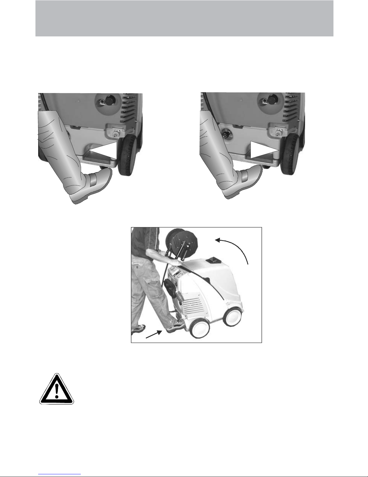
Brake applied
Brake
The Kränzle therm is fitted with a brake that prevents the machine from rolling away
on flat ground.
Always apply the brakes firmly when working with the machine !!!
Brake not applied
If you want to move the
high pressure cleaner
into another direction,
first slightly tilt back the
machine by pressing the
foot rest and pulling the
pushbar at the same
time.
Now you can
move the cleaner
into the desired
direction.
Safety Information
CAUTION !!!
For safety reasons always put the master switch into the
„0“ position (=power switch-off) after completion of work.
When starting the cleaning process do not aim the high pressure
jet at the object to be cleaned for at least 30 seconds.
It is possible, that the water contents in the combustion chamber (approx. 5 litres)
has changed colour due to the resting time.
Safety Information
Page 8

Safety Information
8
Safety Information
Important !!!
The machine must be disconnected from the power supply
when servicing work is being carried out. The master
switch should be in position "0" and the plug out of the socket.
Do not use the cleaner if electrical connections or other
safety-relevant parts (e.g. overpressure valve, high
pressure hose, spraying equipment etc.) are damaged.
The machine may only be used by persons who have
received the necessary training.
Never operate the machine without supervision.
The water spray can be dangerous. It should never be directed at people,
animals, electrical apparatus or the machine itself.
Never direct the spray at power sockets.
Parts of the machine interior and parts of the gun and lance become hot when hot
water is used. Leave the cover of the machine closed when using the machine
and do not touch the metallic parts of the gun and lance.
Children must not use high pressure cleaning equipment.
Do not damage the cable or repair it incorrectly .
Do not pull the high pressure hose if there are kinks or loops in it. Make sure that
the hose is not damaged on sharp edges.
Persons operating the machine should wear the necessary protective clothing, i.e.,
waterproof clothing, rubber boots, safety goggles, headwear etc. It is prohibited to
use the machine in close vicinity to people lacking suitable protective clothing.
The high pressure spray can generate a high level of noise. If noise exceeds the
maximum allowed levels, users and others in the vicinity must wear suitable ear protection.
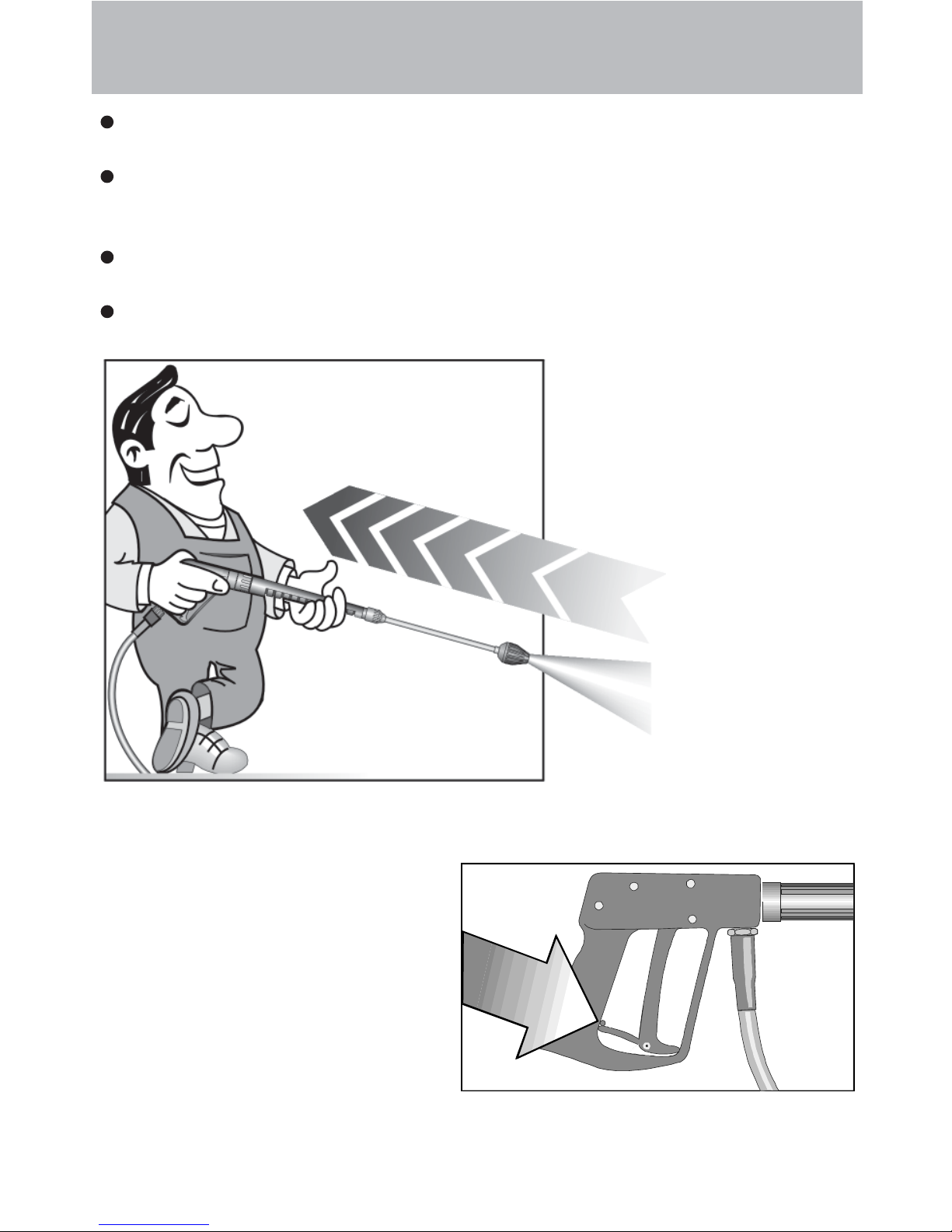
The high pressure spray causes recoil and additional twisting movement if the gun
is angled. The gun must therefore be held firmly with both hands. (see page 2)
Do not close off the exhaust aperture on the topside of the machine. Do not
bend over this aperture and do not put your hands inside it. Exhaust gases are
very hot!
Do not clamp down the trigger of the gun. Apply the safety catch after use, in order
to prevent accidental spraying.
Do not spray against matter containing asbestos or other hazardous substances.
Never spray liquids containing solvents, such as paint thinner , petrol, oil, or anything
similar. Note the specifications of the additive makers! The seals in the machine
are not resistant to solvents. The spray vapour of solvents is highly inflammable,
explosive and poisonous.
Page 9
9
Safety Information
As to the recoil see notice on page 2!
Apply the safety catch on the
spray gun after each use, in
order to prevent unintentional
spraying!
The machine may not be set up and used in rooms where there is a danger of fire
or explosion. The machine may not be used under water .
Air is required for combustion, and exhaust fumes are generated. If the machine is
used in closed rooms, make sure that the exhaust fumes can escape and that
there is adequate ventilation.
Use light heating oil EL (DIN 51 603) or Diesel (DIN EN 590) only . The use of other
fuel is perilous and may even cause an explosion.
Never direct the high-pressure jet at yourself or other persons just to clean clothing
or shoes.
Page 10
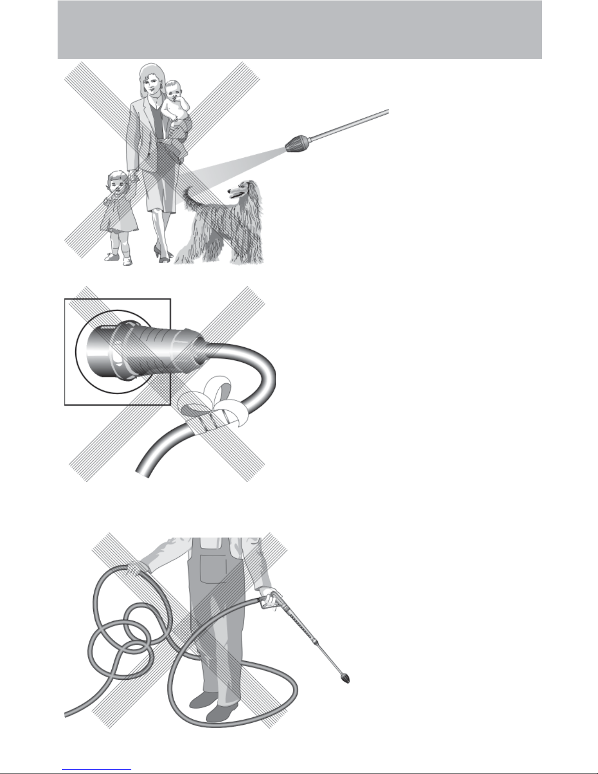
This is prohibited!
10
Do not damage the
power cable or
repair it incorrectly!
Never direct the
water jet at people
or animals!
Never pull the high
pressure hose if it
has for med kinks or
“nooses”!
Never pull the hose
over shar p edges!
Page 11
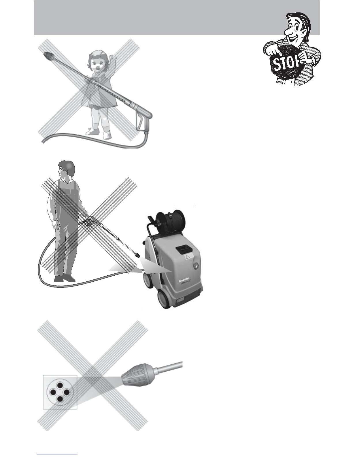
This is prohibited!
11
Never allow
children to use the
high pressure
cleaner!
Never direct the
water jet at the
machine itself!
Never direct the
water jet at a
power socket!
Page 12
Commissioning
12
Electrical connection
Make sure that the master switch is switched off (position „0“).
Plug in the power cable of your high-pressure cleaner.
The voltage given on the specification plate must match the mains voltage. You can
find the specification plate on the front right-hand side of the appliance.
The machine is supplied with a power cable and plug.
The plug must be connected to a properly installed electrical so-
cket with earthing and have a 30 mA FI residual current circuit
breaker. The socket must have a neutral 16A fuse on the mains
side.
If an extension cable is used, it must have an earth line that is properly connected to
the plug connections. The lines in the extension cable must have a cross section of at
least 1.5 mm². The plug connections must be of spray protected design and may not
lie on a wet surface. (If the extension cable is longer than 10 m the minimum cross
section is 2.5 mm²)
Important!
Extension cables that are too long cause a drop in the voltage and
thus interruptions in operation. If you are using a cable drum, the
cable must always be fully unwound.
Commissioning
Secure the machine by applying the brake (see page 8)
and check the oil level of the high pressure
pump.
Do not start the machine if there is no oil on
the dipstick. Fill oil if necessary. See page 18.
Use EL heating oil (DIN 51603) or Diesel fuel only.
Unsuitable fuels, such as petrol, may not be used (danger of
explosion).
Fill the fuel tank with light heating oil prior to use.
Page 13

13
Commissioning
Water connection
Connect the machine to a water tap using a hose of at least 1/2" and turn on the
tap. (2-10 bar admission pressure)
The water tank in the machine fills up. When the tank is full, the built-in float valve
closes the water inlet.
Use clean water only!
CAUTION !
Please pay attention to the regulations of your waterworks company .
In accordance with EN 61770, the machine may not be directly connected to the
public drinking water supply lines.
A brief connection however is permissible according to DVGW (German Association
for Gas and Water Affairs) if a tube ventilator with check valve (Kränzle Order-No.
41.016 4) is built into the water supply .
Also indirect connection to the public drinking water supply lines is permissible by
way of free emission in accordance with EN 61770, e.g. by using a reservoir with a
float valve.
Direct connection to a non-drinking water supply line is permissible.
High pressure connection
Connect the high pressure hose to the handgun.
Unwind the hose so that it is free of loops and connect it to the handgun and the
machine.
Check that all screw-type connections are pressure-tight. Leaks
from gun, high pressure hose or hose drum must be eliminated
immediately. Leakage leads to increased wear.
Page 14
4
Commissioning
- Switch off the ignition. Rocker switch (16) to „0“.
- Set the pressure control (4) valve to maximum pressure
(see below) and close the detergent valve (20).
- Open the gun and switch the master switch (15) on.
The high pressure pump now presses the air out of the
lines, and after a short time the high pressure spray is
formed and the operating pressure is reached.
If the system has to be deaerated (appliance rattles), open
and close the spray gun repeatedly.
CAUTION
After an extended standstill do not instantly aim the high pressure
water jet at the object to be cleaned, as the remaining water
inside the high pressure cleaner may be discoloured.
Commissioning
15 16 17
201918
14
Adjusting the pressure
Use the pressure control valve (4) directly
on the pump head to adjust the pressure.
turn left:
min.
turn right:
max.
The machine is fitted with a Total-Stop-System. If the gun is
closed for longer than approx. 20 seconds, the machine switches
off automatically, after 20 minutes the machine moves to safety
switch off and you must use the master switch to turn it back on.
The machine restarts automatically when the gun is operated,
provided that the master switch is on.
Page 15

15
Commissioning
Usage with detergents
- The detergent must have the ph-value 7-9 neutral.
- Wait until the pump has pressed the air out of the lines.
- Put the chemical filter into a container with detergent.
- Open the detergent valve (20). The pump now sucks detergent in and mixes it
with the high pressure spray.
- Set the desired concentration of detergent.
- At the end of the working procedure with detergent reset the rotary button
to „O“.
- When the high pressure cleaner is operated with open chemistry valve
without chemicals, the pump sucks in air. Damages caused to the pump as
a result are not covered by the guarantee.
Comply with additive manufacturers’ instructions (e.g. protective
equipment and waste water regulations). Use only additives approved
for use with high pressure cleaners. Using other additives impairs
the safety of the machine.
In the interest of the environment and to keep expenditure down, we
recommend sparing use of detergent. Please observe the
recommendations of the detergent manufacturer.
After using detergents, rinse the machine for approx. 2 minutes by
pressing the trigger of the spray gun.
Usage as a cold water high pressure cleaner
- Leave the ignition "OFF". Rocker switch (1A) to „0“.
- Start cleaning
Usage as a hot water high pressure cleaner
- Set the target temperature on the thermostat to min. 40 °C and than switch the
ignition "ON" (rocker switch) .The oil burner starts to work. The water is heated up
and kept at the temperature you have set.
During high-pressure operation (above 30 bars) the temperature may not exceed 90 °C.
Steam level
To reach the steam level, i.e. over 90 ° C water temperature, adjust the pressure and
the water quantity downwards using the handwheel ( 4 ) and choose the desired
temperature of max. 150 °C with the thermostat. For high pressure cleaners with hose
drum applies: The hose must always be fully unwound.
During steam operation the pressure may not exceed 30 bars.
Page 16

Decommissioning
16
Decommissioning
- Switch off the master switch (position "0").
- Pull the plug out of the power socket.
- Turn off the water supply.
- Open the gun until the pressure is gone.
- Lock the gun.
- Disconnect the water hose.
- Slacken the connections of the high pressure hose and gun and unscrew the high
pressure hose from the machine (appliances without hose drum).
Anti-Freeze Protection
The machine is normally still partially filled with water after work has been completed.
It is therefore necessary to take special precautions to protect the machine from frost.
- Completely empty the machine of water
Disconnect the machine from the water supply and switch off the ignition.
Switch on the master switch and open the gun. The pump now presses the
remaining water out of the heating coil. Do not allow the machine to run for
longer than a minute without water.
- Fill the machine with anti-freeze
If the machine is not in use for lengthy periods of time, it is advisable to
pump anti-freeze into the machine, especially in winter. For this purpose, fill the
antifreeze agent into the water box and turn on the machine without ignition
(rocker switch (16) to „0“). Wait with opened gun, until the agent comes out of
the nozzle.
However, the best protection against frost is to keep
the machine in a place that is safe from frost.
Page 17
17
Care and Maintenance
1
Care and Maintenance
Care and maintenance is required to keep the machine in good working order, and
to allow you to enjoy the machine for as long as possible.
IMPORTANT!!!
Always remove the plug before working on the machine!
Only use original Kränzle spare parts
What to do!
- Weekly, or after approx. 40 hours of operation
Check the oil level of the high pressure pump. (see page 13)
If the oil level is too low, add oil until the oil level is between the two markings on
the oil measuring rod.
Change the oil (see page 19) if it has a grey or whitish appearance. The oil should
be disposed of responsibly.
Check the filter in front of the float valve in the water tank and the fuel filter
in front of the solenoid valve. Clean the filters if necessary.
- Yearly, or after approx. 500 hours of operation
Desulphurise and decarbonize the heating coil.
Check if the heating coil is calcified (see page 20).
Check the oil burner and ignition system.
Clean the oil nozzle, oil filter, solenoid valve and filter, clean and adjust the
ignition transformer, ignition cable and ignition electrodes and replace defective parts.
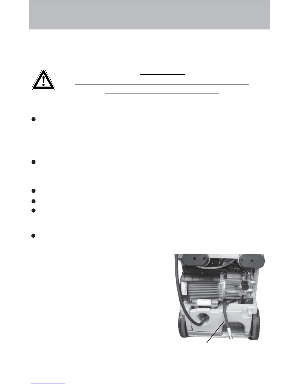
Change the oil
Changing the oil
To do this, take the oil drainage hose (1)
connected to the oil drain screw , from the inside
of the machine and open the red oil filler cap on
the top side of the black oil reservoir . Open the
cap at the end of the hose. Drain off the oil into
an oil pan and dispose of it responsibly .
Close the end of the hose.
Refill with oil.
Page 18

Care and Maintenance
18
Fuel System
IYour fuel may contain particles of dirt, or impurities or
water may get into the tank during refuelling.
As a safeguard for the fuel pump the appliance is fitted
with a fuel filter (c). Check regularly if the filter is soiled
and clean it if necessary.
Check the tank for impurities on a regular basis.
Empty the fuel tank using the drainage screw (d) at the
bottom of the tank. Clean the tank and the fuel lines
carefully. Screw in the drainage screw.
Detergent and dirty fuel must be
disposed of responsibly.
Adjusting ignition electrodes
For a smooth ignition, the setting of the ignition electrode must be controlled
regularly.
Oil leakage
If oil leaks out, go to the nearest customer service (dealer) immediately .
(Environmental damages, transmission damages, loss of guarantee.)
Type of oil: Formula RS of Castrol - Quantity: 1.0 l
Check distance in mm
c
d
Page 19

19
Care and Maintenance
Decalcifying the heating coil
Calcified machines use an unnecessary amount of energy because the water can only
be heated slowly and the excess pressure valve feeds a part of the water back into the
pump circuit.
Calcified machines can be recognised by increased pipeline resistance.
Check pipeline resistance by disconnecting the high pressure lance from the gun and
switching the machine on. A full jet of water emerges from the gun. The machine must
be decalcified if the pressure shown on the manometer is greater than 25 bars.
Decalcifiers are caustic!
Observe the instructions for usage and accident prevention. Wear
protective clothing to prevent the decalcifying agent from contacting
your skin, eyes and clothing (e.g. gloves, safety mask etc.)
Proceed as follows to decalcify the machine:
Unscrew the high pressure hose from the machine and decalcify it separately.
Put the detergent suction hose into a container of decalcifying solution.
Set the dispenser valve to the maximum concentration.
Switch on the machine.
Hold the gun in a separate container and press the trigger.
Wait for about a minute until the decalcifier comes out of the gun
(recognisable by its whitish colour).
Switch off the machine and allow the solution to act for about 15-20 minutes.
Switch the machine back on and rinse it through with clear water for about 2
minutes.
Now check whether pipeline resistance is back to an acceptable level. Repeat the
decalcifying process if the pressure without the high pressure lance is still above 25
bars.
Page 20

Care and Maintenance
20
Rules, directives, inspections
Inspections performed by Kränzle
- measurement of earth line resistance
- measurement of voltage and current
- inspection of tension consistency with +/- 1530 V
- pressure check of heating coil at 300 bar
- visual and functional check as per the inspection sheet provided
- exhaust fume analysis (see test strips provided)
Guidelines for liquid sprayers
The machine conforms with the "Guidelines for liquid sprayers". These
guidelinesare issued by the organisation of trade associations and may be
obtained from Carl Heymann-Verlag KG, Luxemburger Str. 49, 50939 Köln.
These guidelines specify that this machine is to be inspected by qualified
personnel whenever necessary, but no less than once every 12 months.
These inspections must be recorded in the inspection log at the end of this
manual.
Pressure container and steam boiler directives
Kränzle high pressure cleaning equipment conforms to the pressure container
and steam boiler directive. No construction approval, notification of licence and
takeover inspection are required. The water capacity is less than 10l.
Duties of owner
The owner is to ensure that all safety-relevant components are in a serviceable
condition before the sprayer is used. (e.g., safety valves, hose and electric
cables, spray equipment etc).
Emission control legislation
With stationary installation, the emission levels of the machine must be checked
once a year by a qualified organisation or person according to German law.
The first inspection must be carried out four weeks after the machine is
commissioned. The owner is responsible for having the inspection performed.
Page 21

21
Description of function -Troubleshooting
5 Hand wheel for pressure adjustment
6 High pressure pump
7 Pressure switch black (start solenoid
valve)
8 Pressure switch red (start pump)
9 Safety valve
10 Flow controller
11 Motor for ventilator and fuel pump
1 2 Solenoid valve (Fuel)
13 Fuel pump
IMPORTANT!!!
Always remove the plug before working on the machine!
14 Fuel manometer
1 5 Fuel filter
16 Ignition transformer
17 Thermosensor water
18 Ignition electrodes
1 Master switch
2 Ignition “ON/OFF
3 Brief operating instructions
4 Thermostat
1
2
3
4
56 9
10
78
11
12
15
16
17
14
13
18
Page 22

Cold water mode
1. Connect to water supply and determine whether the water tank fills up
completely and the float valve stops.
2. Ignition (2) to OFF.
3. Main switch (1) to ON.
4. Open high pressure gun. The apliance started, the pump sucks water from the
water tank and moves the water through the heating coil to the lance, the
pressure is increased.
A TTENTION!!
If the pressure is not built up immediately, there is still air
in the pump. Open and close the gun repeatedly to press
the air from the machine.
Description of function -Troubleshooting
Hot water mode
Start the machine just like in cold water mode and then turn the rocker switch (2) for
the burner to ON. Then, turn the rotary switch on the thermostat, (4) located on the
front, to the desired temperature (at least 40 °C) in order to activate the burner , i.e.,
that fuel is injected.
The manometer (14) on the fuel pump shows approx. 10 bars. If this reading is not
displayed, check whether
1. there is heating oil in the tank
2. the motor fuse ( 11) in the switch box (below the operation panel) has tripped.
3. the fuel sieve (15) or the fuel sieve in the pump (13) is dirty.
4. the fuel pump does no operate smoothly or is blocked.
5. the ventilator jams.
The thermostat grants permission to open the solenoid valve. The burner starts and
heats up the water to the set temperature. The burner switches off as soon as the
desired temperature has been reached.
If the temperature drops again, the burner switches on automatically thus guaranteeing
the required constant temperature.
22
Page 23

23
Description of function -Troubleshooting
Control board (p. 28-29)
The control board is equipped with two LEDs for trouble shooting.
L1: - permanently illuminated, if the overcurrent release has tripped.
- blinking, if the fuel flow valve detects only a low quantity of fuel in the tank or if
it is defctive.
L2: - illuminated, if the burner has been released but the flame is not burning. If the
flame starts burning within 2 seconds, the LED goes out.
If the LED does not go out the combustion has to be checked. If the LED is
not illuminated at all, the flame sensor has to be checked.
Nevertheless the cleaner can be used as a cold water high pressure cleaner
even if the burner is switched off.
The thermostat (4) is controlled via a thermo-sensor (18) mounted at the outlet of the
heaiting coil.
In the switchbox (below the operating panel), a fuse (F1) is installed on the board
protecting the motor (11) of the fuel pump and the ventilator. If the motor is overloaded
the fuse trips. This may happen if the fuse pump is blocked or sluggish - the same
applies if the ventilator is blocked or sluggish or in case of an electrical malfunction.
Another fuse (F2) on the board trips, if the ignition transformer (17) is faulty.
To avoid an overheating of the burning chamber a flow indicator (10) is installed in the
high pressure system between the high pressure pump (6) and the burning chamber
enabling a fuel supply only if water streams through the heating coil at the same time.
Page 24

IMPORTANT!!!
Always remove the plug before working on the machine!
Troubleshooting
24
Malfunction Cause of malfunction / Trouble shooting
Water supply
Water tank runs over.
Water tank does not fill completely.
Pump does not suck.
Test: check water and chemical
system for tightness.
Float valve is dirty.
Float valve is defect.
Float valve is defect
Water filter soiled.
Check water inlet quantity.
Valves stick or are di rty.
Suction hose leaks.
Chemistry valve is open or leaks.
Check hose clips (connections).
High-pressure nozzle is clogged.
Connect water inlet directly to the pump (2-4
bar pre-pressure).
Disconnect suction lines below the pump.
High-pressure pump
Pump makes lots of noise.
Operating pressure is not reached.
Water drops from the pump.
Oil drops from the transmission.
Pressure is too low
Pump sucks air. Check suction connections.
Check high-pressure nozzle.
Check valves.
Check O-rings under valves.
Check sleeves.
Manometer is defect.
Unloader: check stainless steel seat and ball.
Check seals on the control piston.
Replace sleeves in the pump.
Replace O-rings.
Check oil seals (replace).
Check plunger and plunger guides.
Check water supply, since water deficiency or
air suction can cause damage to seals and Orings (chemistry valve leaks?).
Worn high pressure nozzle
Stainless steel seat, ball, O-ring in unloader is
dirty or defect.
Manometer is defect
Page 25

25
Troubleshooting
Malfunction Cause of malfunction / Trouble shooting
Machine does not switch off
Test: Jumper (red) pressure switch
Check return body and O-ring in unloader of the
valve hous ing.
Check pressure switch (red).
Check micro switch.
Check cable connections.
Boar d is def ec t.
Appl i anc e does n ot s t a r t o r
stopps during operation
C heck electricity supp ly.
Check main switch.
Check cable connections.
Check board.
Check pressure switch.
Sw itch off b
y
overcu rren t rel ease.
Heating (burner)
Fuel pump/blower operates, but
burner doe s not heat.
Fuel pump/blower does not
operate.
- Pump makes lots of noise
- Fuel operating pressure has not
been reached
Coupling betwee n burner motor
and fuel pump is broken
Set water temperature is reached.
Increase temperature on thermostat with rotary
control switch.
Open gun, until temperature drops.
Fuel tank is empty.
Fuel filter is dirty.
Fuel nozzle is dirty.
Blower/fuel pump motor is defect.
Check electrical equipment.
Check fuse in terminal box.
Coupling between burner motor and fuel pump
is defect.
Wate r in fuel tan k.
Dirt or rust in the fuel pump.
Clean tank.
Replace fuel pump.
Burning
Smoke during operation
Smoke after switching off
Fuel is dirty.
Nozzle or nozzle stock leaks.
Wate r in tank.
Page 26

26
Troubleshooting
Malfunction Cause of malfunction / Trouble shoooting
Solenoid valve on the fuel pump
does not ope n
Test : Pres su re switch (black )
Bridge in terminal box between
terminal 3 +4
Test: Connect solenoid valve 230
V ex t ernal ly
Oil pressure on the fuel pump is
too low
too high
C he ck pressur e sw itch (black).
Solenoid valve is defect or dirty.
Clean filter, clean supply line, clean fuel pump.
Se tt i ng is wr ong .
Clean fuel nozzle, or repl ace it.
Ignition does not function
Check igni tion cable.
Charring of plug-in contacts by moisture.
Cable is brok en
Check ignition transformer connections.
Transformer is def ect
Ignition electrode has been falsely set or burnt
up.
Ventilator does not operate
Blower- /fuel pum p motor is defect.
Check electrical equipment.
Check fuse in terminal box.
Coupling between burner motor and fuel pump
is defec t.
Sp ray gun -
High- pres sur e hose
Gun drips
High pressure hose drips
Noz zle is cl ogg ed
Check for leakages.
Replace seals.
Replace O-ring under screwed connection.
Ma nomet er indic at es pre ss ure, but no wat er
comes out of HP-hose
–
clean nozzle.
S ucking detergent
Detergent is not sucked
Pump sucks air.
C he ck hose clips.
Test:
Connect water line to the pump.
Water inlet: 2 - 4 bar pre-pressu re . No w ater
must com e from the deter
g
ent hose.
Page 27

27
High
pressure
connection
Heating chamber
Water inlet
Detergent
Pipeline plan
Safety valve, number
5 must be set approx.
15 % higher than the
unloader valve on the
HP pump
1 Float valve, water inlet
2 Water tank
3 Control valve, detergent
4 High pressure pump
with integrated unloader valve
5 Pressure switch Motor Start/Stop
6 Pressure switch Burner release
7 Safety valve for heating coile
8 Flow controller
9 Fuel pump with solenoid valve
10 Fuel filter
1 1 Fuel tank
Warranty
This warranty covers material and/or workmanship related defects only and does not
extend to ordinary wear.
Machine must be operated according to enclosed operating instructions which are part of
present warranty conditions.
A
ll products sold directly to private customers are warrantied for a period of 24 months,
whereas the warranty period for industrial purchases is limited to 12 months.
In case of any warranty claims , please have your HP cleaner together with accessories
and your purchase document ready and contact your nearest dealer or authorized service
point which can also be looked up in the internet at www.kraenzle.com .
Warranty is void in case of attempts to modify any of the safety devices or in the event of
exceeding temperature or rpm limits - this also applies to undervoltage, low water and/or
polluted water. Gauge, nozzle, valves, sealing gaskets, high pressure hose and spray
e
quip
ment are considered wear parts and do not fall under this warranty.
Page 28

28
Circuit diagramme 230V / 50Hz
Connection via
grounding plug
230 V / 50 Hz
Master switch
A.C. motor
High pressure pump
Excess
current actuator 15 A
Switch
Heating
Burner
motor
Ignition
transformer
Fuel
valve
Flow controller
Pressure switch Burner release
Pressure switch Motor Start/Stop
Ord.-No:
44.952
F1 F2
Sensor line
Thermostat
Thermostat
with rotary
switch
Pressure switch
Motor Start/Stop
Pressure switch
Burner release
Flow controller
Burner release
Sensor
Water
temperature
Interf. suppr. for
ignition
transformer
installed on board
Page 29

Circuit diagramme 400V / 50Hz
29
Connection via
CEE 4x 16 A
380 V 50 Hz +MP
Master switch
Three-Phase motor
High pressure pump
Excess
current actuator 8,5 A
Switch
Heating
Ord.-No:
44.952
Flow controller
Pressure switch Burner release
Pressure switch Motor Start/Stop
F1 F2
Sensor line
Thermostat
Thermostat
with rotary
switch
Pressure switch
Motor Start/Stop
Pressure switch
Burner release
Flow controller
Burner release
Sensor
Water temperature
Burner
motor
Ignition
transformer
Fuel
valve
Interf. suppr. for
ignition
transformer
installed on board
Page 30

30
Complete Assembly
Page 31

31
Kränzle therm CA
No. Description Qty. Order No.
Spare parts list KRÄNZLE therm CA
Complete Assembly
No. Description Qty. Order No.
1 Fahrgestell 1 44.800
2 Achse 4 44.820
3 Rad d250 4 46.010 2
4 Federstecker 4 40.115 1
5 Radkappe 4 46.011
6 Schraube M6x30 DIN912 8 43.037
7 Wasserkasten schwarz 1 44.805 1
8 Schraube M6x16 DIN912 3 44.831
9 Tankdeckel mit Pos. 10 1 44.833
10 O-R i ng 70 x 5 1 4 4.020
11 Brennstofftank schwarz 1 44.806 1
12 Haube hinten 1 44.812
13 Schraube M5x14 DIN7985 6 40.536
14 Haube vorn 1 44.813
15 Kaminblende 1 44.825
16 Schubbügel 1 44.834
17 Köchertopf 1 46.503
18 Lanzenhalter 2 42.610
19 Lanzenständer 1 46.502
20 Schraube M6x16 2 40.171 1
21 Blechschraube 3,5x16 DIN7981 8 44.161
22 Schraube M6x35 DIN6912 2 46.024
23 Schraube M5x16 DIN7985 4 40.178
24 Deckel Zuluft 1 44.801
25 Ablassschraube 2 44.004 1
26 Dichtung für Ablassschraube 2 41.047 1
27 Scheibe DIN9021 8,4 4 41.409
28 Schraube M8x80 DIN931 4 44.832
29 Scheibe Haubenbefestigung 6 44.849
30 Scheibe DIN9021 8,4 4 41.409
31 Schraube M 8 x 110 DIN931 4 44.826
32 Scheibe D40x19x1,5 16 46.533
36.1 Motor-Pumpe für therm CA 11/130 1 44.960
36.2 Motor-Pumpe für therm CA 12/150 1 44.961
36.3 Motor-Pumpe für therm CA 15/120 1 44.962
37 Hochdruckschlauch NW 8 10 m 1 44.878
38 O-Ring 9,3 x 2,4 Viton 2 13.273 1
39 Pistole mit Lanze und HD-Düse 25045 1 12.164 1-D25045
(CA 11/130; CA 12/150)
39.1 Pistole mit Lanze und HD-Düse 25070 1 12.164 1-D25070
(CA 15/120)
40 Gummidämpfer 4 44.891
41 Motorträger 1 44.950
Page 32

32
Electronics switchbox
Page 33

33
Kränzle therm CA
No. Description Qty. Order No.
ESpare parts list KRÄNZLE therm CA
Electronics switchbox
No. Description Qty. Order No.
1 Elektrokasten 1 44.807 1
2.1 Deckel für Elektrokasten therm CA 11/130 1 44.808 6
2.2 Deckel für Elektrokasten therm CA 12/150 1 44.808 7
2.3 Deckel für Elektrokasten therm CA 15/120 1 44.808 8
mit Dichtung
3 Frontplatte Manometer 1 44.809 1
4 Kabelaufwicklung 2 44.822
5 Schraube 5 x 25 4 41.414 1
6 Bock für Schalter 1 44.810
7 Schraube 5x14 10 43.426
8 Bock für Thermostat 1 44.811
9 Dichtung für Thermostat 1 44.818
10 Dichtung für Schalter 1 44.817
11 Schalter 2 44.835
12 Drehgriff Thermostat 1 44.153
13 Gewindeschneidschraube M 2,5 x 8 1 44.168
14 Thermostat drehbar elektronisch 1 44.951
15 Deckel für Übertemperaturauslöser 1 44.182
16 PG16 – Blindstopfen 2 44.890
18 Schraube 4,0 x 16 8 43.417
19 Erdungsklemme 1 44.839
20 Feinsicherung M 1,25 A 1 44.676
20.1 Feinsicherung M 2,5 A 1 44.889 2
21 Schraube M4x8 DIN84 2 46.604 1
22 Steuerplatine 230 V / 50/60 Hz 1 44.952
23 Schütz 400 V / 50/60 Hz 1 46.005 1
23.1 Schütz 230 V / 50/60 Hz 1 46.005
24 Schraube 4,0 x 25 mit angepr. Scheibe 2 43.425
25 Überstromauslöser 8,5A 3-pol . 1 46.040
25.1 Überstromauslöser 15A 1-pol. 1 46.041
26 Kabel trompete mit Zugentlastung 1 44.819 1
27 Zugentlastungsschelle 1 43.431
28 Schraube 3,5 x 14 2 44.525
29 Netzanschlußleitung Drehstrom 1 44.036
8,0m, 4x 1,5 mm², H07RNF
29.1 Netzanschlußleitung Wechselstrom 1 41.092
5 ,75m, 3x 1, 5 mm ², H0 7RNF
30 PG16-Verschraubung 1 Durchführung 2 41.419 1
31 PG16-Verschraubung 2 Durchführungen 1 44.132
32 PG16-Verschraubung 3 Durchführungen 1 44.133
33 Manometer 1 15.039 1
34 Gehäuse Waschmittelventil 1 44.145
35 O-Ring 5 x 1,5 (Viton) 1 44.150
36 O-Ring 28,24 x 2,62 1 44.149
37 Regulierkolben Chemieventil 1 44.147
38 Edelstahlfeder 1,8 x 15 x 15 1 44.148
39 Deckel für Chemieventil 1 44.146
40 Blechschraube 3,5 x 16 3 44.161
41 Blechschraube 3,5 x 19 2 44.162
42 Drehgriff Chemieventil mit B lendkappe 1 44.151
44 Schraube 5,0 x 20 mit angepr. Scheibe 10 43.018
45 Durchführungstülle 2 44.823
46 Dichtung für Deckel Übertemp. 1 44.182 1
47 Dichtung Elektrokasten 1 44.838
48 Klemmbügel für Manometer 1 44.049
49 Anschlußmuffe Manometer 1 44.136
50 Kunststoffschraube 4,0 x 25 8 43.425
51 Schlauchklemme 9 - 9 2 44.054
52 Schlauch für Waschmittelansaugung 1 44.055
53 Schlauch mit Filter und Rückschlagv. 1 44.056 1
54 Rückschlagventil für Waschmittelans. 1 44.240 1
55 Druckmeßleitung 1 44.102
Chemieventil kpl. Pos. 34-42 44.052
Page 34

34
No. Description Qty. Order No.
Water supply and brake
1 Wassertank 1 44.805 1
4 Schwimmerventil 1 46.250
5 Moosgummidichtung 1 46.261
6 Mutter R3/4“ 1 46.258
7 Kunststoffschraube 5x14 1 43.426
8 Scheibe 5,3 DIN9021 1 50.152
9 Zugfeder 1 46.020
10 Deckel Bremse 1 46.016
11 Hebel Bremse 1 44.804
12 Zylinderschraube M 8 x 20 1 41.480
13 Innensechskantschraube M4x10 4 46.002
14 Schelle 2 43.431
15 Bolz en für Bremse 1 46.0 18
16 HD-Schlauch Wasserausgang 1 44.840
17 Haltescheibe 1 44.841
18 Ausgangsteil R1/4“ x ST30 1 44.855
19 Schr aube DIN912 M5 x12 2 4 1. 0 19 4
20 Zahnscheibe 5,1 2 43.483
Brake compl. Pos.7-15 44.880
Page 35

Fuel filter compl. Pos. 15 - 21 44.881
Fuel pump compl. Pos. 22-26, 28, 29 ,31 44.852 1
35
No. Description Qty. Order No.
Fuel supply
1 Deckel Brennstoffversorgung 1 44.011
2 Flansch mit Brennstoffleitungen 1 44.842
3 Gummidichtung 1 44.012
7 PA-Sc hl auch DN6 0, 4 m 44.403
8 PA-Sc hl auch DN6 0, 3 m 44.403
9 PA-Sc hl auch DN6 0, 4 m 44.403
10 Steckverbinder 6 - 6 1 44.404
11 Schraube 5,0 x 25 3 41.414 1
12 Steckverbinderstutzen 1/8“ x 6 1 44.407
13 Ermeto-Verschraubung R1/8“ x 6L 1 44.372
14 Steckv e r binde rw inkel 1/ 8“ x 6 1 44. 4 08
16 Anschlussteil Brennstofffilter R1/4“ 2 44.214
17 Gummidichtung 3/4" 2 41.047 1
18 Filtergrundkörper 1 13.301
19 Gummidichtung 1 13.303
20 Siebkörper Brennstofffilter 1 44.213
21 Filterbecher 1 13.302
22 Einschraubwinkel R1/4" AG x 10L 2 40.121 1
23 Brennstoffpumpe mit Magnetventil (Pos. 23, 26, 31) 1 44.852
24 Brennstoffmanometer 0-15 bar R1/8" 1 44.082
25 Magnetspule für Magnetventil 1 44.892
26 Magnetventil 1 44.251
27 Abstandsrohr 128 mm 1 44.084
28 Steckverbinderwinkel 1/4" x 6 1 44.405
30 Brennstoffzuleitung 1 44.845 1
31 Doppelnippel 1/4“ x 1/ 4“ 1 44.25 1 2
Page 36

36
Combustion chamber
Page 37

37
No. Description Qty. Order No.
Kränzle therm CA
Spare parts list KRÄNZLE therm CA
Combustion chamber
Blower-fuel pump unit Pos. 20 - 33 44.882
Flow controller compl. Pos. 41 - 45 12.600 1
1 Gebläsegehäuse 1 44.802
2 S chraube M 5 x 10 5 43.021
3 Schraube 3,9 x 9,5 3 41.079
8 Federring A 8 5 44.222
9 E delstahlmutter M 8 2 14.127 2
10 Tiefenanschlag 1 44.088
11 Brennstoffleitung „Düsenstock“ 120 mm 1 44.089
12 Winkelverschraubung 6L x 6L 1 44.106
13 Brennstoffleitung Pumpe 1 44.845
14 Ed elstahlsc hraube M 6 x 10 3 44. 177
15 Halterung Zündtrafo 1 44.821
16 Scheibe DIN9021 4,3 4 43.472
17 Schraube 3,9 x 13 4 41.078
18 Zündtrafo 1 44.851
19 Schraube 4,0 x 60 4 43.420
20 Deckel Gebläsegehäuse 1 44.803
21 Schraube 4,8 x 16 4 40.282
22 Lüfterrad 1 44.847
24 Lüfterm otor 230 V / 50 Hz, DR rechts 1 44.850
25 Steckkupplung 1 44.852 2
26 Brennstoffpumpe kpl. 44.852 1
27 Hochspannungszündkabel 1 44.114 2
29 Zyl.schraube mit ISK M 5 x 12 DIN 912 1 40.134
31 Fächerscheibe 4,3 4 43.471
32 Schraube M 4 x 10 4 43.470
33 Gewindestift M 6 x 8 DIN 914 1 44.090
34 L-Verschraubung 1 44.869
35 Temperaturfühler 1 44.954
36 Ermetomutter 12 mm 2 40.075
38 Ermtorohr 12x85 mit Mutt er n und Schnei dr ing 1 44.848
39 Winkelverschraubung 12L x 12L 1 42.630
40 Einschraubwinkelverschr. 3/8" x 12L 2 44.092
41 Grundkörper Strömungswächter 1 12.601
42 Strömungskörper 1 12.602
43 Abdeckung 1 12.603
44 Schraube M 4 x 8 4 44.216
45 Eingangsteil 3/8“ x 12 mit Mutter und Schneidring 1 12.604
46 Magnetschalter 1 40.594 1
47 Schlauchführung 1 44.830
48 Schraube M 5 x 14 2 40.536
50 Hochdruckschlauch Wasserausgang 1 44.840
51 Abschlussring 2 44.086
52 Gewindestift M 6 x 8 DIN 914 2 44.090
54 Fühler Muffe 1 44.171
55 Mutter 1 44.172
Page 38

38
Combustion chamber
Page 39

No. Description Qty. Order No.
Kränzle therm CA
Spare parts list KRÄNZLE therm CA
Combustion chamber
39
1
A
ußenmantel mit Z ugbolzen 1 44.860
3 Innenmantel mit Bodenplatte 1 44.064 1
4 Deckel Düsenstock 1 44.079
5 Innendeckel mit Kamin und Flammrohr 1 44.861
6 Außendeckel 1 44.862
7 B rennstoffdüse 60° B 1,35 gph 1 44.077 2
( CA 11/130; CA 12/150)
7.1 Brennstoffdüse 60° B 1,5 gph 1 44.077
(CA 15/120)
8 Blockelektrode 1 44.854
9 Düsenstock Ø 25 mm, 6 Schl. 1 44.076 4
10 Düsenhalter 1 44.078
11 Ed elstahlsc hraube M 6 x 10 3 44. 177
12 Klemmbl ech für Elektrode 1 44.076 1
13 Zyl.schraube mit ISK M 5 x 15 DIN6912 1 44.076 2
15 Abschlusshülse 2 44.081
16 Schraube M 6 x 12 DIN 933 2 44.090 1
19 Edelstahlmutter M 8 7 14.127 2
20 Federring A 8 7 44.222
21 Schauglas 1 44.258
22 Schraube M 4 x 12 DIN7985 4 41.489
25 Heizschlange 1 44.226
26 Flammprallplatte Edelstahl 1 44.224
27 Isolationsplatte 1 44.223
28 Zugbolzen 10 44.863
29 Spannstift 4 x 14 10 44.829
30 Zahnscheibe 4,3 10 43.471
31 Schraube DIN912 M 4 x 10 10 46.002
Page 40

40
Unloader and pressure switch
80 Guide piston compl. 40.490
81 Output piece for red switch, compl. 15.009 3
82 Pressure switch (red) compl.
with cable 0,49 m 44.120 1
83 Ventilgehäuse kpl. 44.320
84 Pressure switch (black) compl.
with cable 0,59 m 44.120
85 Output piece for black switch, comp. 15.011 1
No. Description Qty. Order No.
Page 41

41
Kränzle therm CA
Spare parts list KRÄNZLE therm CA
Unloader and pressure switch
No. Description Qty. Order No.
5 O-Ring 16 x 2 1 13.150
5.1 O-Ring 13,94 x 2,62 1 42.167
8 O-Ring 1 12.256
9 Edelstahlsitz 1 14.118
10 Sicherungsring 1 13.147
11 Edelstahlkugel 8,5 mm 1 13.148
12 Edelstahlfeder 1 14.119
13 Verschlussschraube 1 14.113
14 Steuerkolben 1 14.134
15 Parbaks 16 mm 1 13.159
16 Parbaks 8 mm 1 14.123
17 Spannstift 1 14.148
18 Kolbenführung spezial 1 42.105
19 Mutter M 8 x 1 2 14.144
20 Ventilfeder schwarz 1 14.125
21 Federdruckscheibe 1 14.126
22 Nadellager 1 14.146
23 Handrad 1 40.457
24 Kappe Handrad 1 40.458
25 Elastic-Stop-Mutter 1 14.152
26 Parbaks 7 mm 1 15.013
27 Ausgangsteil R1/4" AG 1 15.011
49 O-Ring 3,3 x 2,4 1 12.136
50 O-Ring 5 x 1,5 1 15.014
51 Führungsteil Steuerstößel 1 15.009 1
52 O-Ring 12,3 x 2,4 2 15.017
53 O-Ring 14 x 2 1 43.445
54 Parbaks 4 mm 3 12.136 2
55 Stützscheibe dm 5 1 15.015
55.1 Stützscheibe dm 4 2 15.015 1
56 Edelstahlfeder 1 15.016
57 Steuerstößel lang 1 15.010 2
58 Parbaks 1 15.013
59 Stopfen M10x1 (durchgebohrt) 1 13.385 1
60 Gehäuse Elektroschalter (schwarz) 1 15.007
60.1 Gehäuse Elektroschalter (rot) 1 15.007 1
61 Gummimanschette PG 9 1 15.020
62 Scheibe PG 9 1 15.021
63 Verschraubung PG 9 1 15.022
64 Kabel 2 x 1,0 mm² 1,10 m grau 1 44.871
64.1 Kabel 2 x 1,0 mm² 1,10 m schwarz 1 44.235
65 Blechschraube 2,9 x 16 6 15.024
66 Deckel Elektroschalter (schwarz) 1 15.008
66.1 Deckel Elektroschalter (rot) 1 15.008 1
67 O-Ring 44 x 2,5 1 15.023
68 Mikroschalter 1 44.262
69 Zylinderschraube M 4 x 20 2 15.025
70 Se c hskant-M ut ter M 4 2 1 5.026
72 Druckfeder 1 x 8,6 x 30 1 40.520
73 Grundteil Elektroschalter 1 15.009
74 Steuerkolben 1 15.010
75 Aluminium-Dichtring 2 13.275 1
Page 42

42
Safety valve for heating coil
No. Description Qty. Order No.
Safety valve for
heating coil
(Adjustment must be approx. 15%
above the operating pressure)
Guide piston compl. Pos. 10-15; 21-23 14.110 1
Safety valve compl. Pos. 1-15; 21-42 44.888
1 Ventilkörper 1 14.145
4 Ermetoverschraubung R 3/8" x 12 mm 1 40.076
6 Ermetowinkel 12 mm x 12 mm Mutter 1 44.865
7 Stopfen R1/4" 1 13.387
8 O-Ring 1 13.275
10 Spanstift 1 14.148
11 Steuerkolben 1 14.133
12 O-Ring 1 13.150
13 Kolbenführung 1 14.130
14 Parbaks 16 mm 1 13.159
15 Parbaks 8 mm 1 14.123
21 Ventilfeder 1 14.125
22 Federdruckscheibe 1 14.126
23 Sechskantmutter M 8 x 1 2 14.144
33 Rücklaufschlauch S200 1 44.867
34 Einschraubwinkel 1 40.121
35 O-Ring 11 x 1,44 1 12.256
36 Edelstahlsitz 1 14.118
37 Sprengring 1 13.147
38 Edelstahlkugel 8,5 mm 1 13.148
39 Edelstahlfeder 1 14.119
40 O-Ring 15 x 2 2 13.150
41 Eingangsstück M20x1,5" x R1/4“ 1 13.136 1
42 Anschlussteil Druckmessleitung 1 44.868
43 Verbindungsschlauch 12mm S200-Strömungw. 1 44.866
Page 43

43
Pump
No. Description Qty. Order No.
23
1 Gehäuseplatte mit Dichtungen 1 40.471
2 Öldichtung 18 x 28 x 7 3 41.031
3 O- Ring 113,97 x 2,62 1 40.474
4 Plungerfeder 3 40.453
5 Federdruckscheibe 3 40.454
6 Plunger 18mm (AM-Pumpe) 3 40.455
7 Sprengring 3 41.035
8 Wellenscheibe 1 40.043
9 Axial-Rollenkäfig 1 40.040
10 AS-Scheibe 1 40.041
11.1 Taumelscheibe 9,0° (therm CA 11/130) 1 40.473-9,0
11.2 Taumelscheibe 9,85° (therm CA 12/150) 1 40.473-9,85
11.3 Taumelscheibe 12,25° (therm CA 15/120) 1 40.473-12,25
12 Schraube DIN912 M 8 x 30 6 41.036 3
13 Ölschauglas 1 42.018 1
14 O-Ring 14 x 2 3 43.445
15 Dichtung Öldeckel 1 41.019 3
16 Öldeckel 1 41.023 1
17 Schraube DIN912 M 5 x 12 4 41.019 4
18 Verschlussstopfen R 3/8“ 1 40.051
19 O-Ring 98 x 1,5 1 40.475
20 Ölgehäuse kpl. 1 40.470 1
21 Motor- Lager Kegelrollenlager 31304 1 40.472
22 Öldichtung 25 x 35 x 7 1 41.024
23 Öleinfüllschraube 1 43.819
Page 44

44
V alve housing
Page 45

Kränzle therm CA
45
Spare parts list KRÄNZLE therm CA
V alve housing AM f or plunger diameter 18 mm
No Description Qty. Ord.-No
Ventilgehäuse kpl. 44.320
Rep.-kit valves for APG-pump 41.748 1
consisting of: 6x Pos. 4; 6x Pos. 5; 6x Pos. 6
Repair kit sleeves 18 mm 41.049 1
consisting of: 3x Pos. 27; 3x Pos. 28;
3x Pos. 28.1; 6x Pos. 29; 3x Pos. 30
1 Ventilgehäuse AM-Pumpe 1 40.451
2 O- Ring 15 x 2 6 41.716
3 Ventile (grün) für APG-Pumpe 6 41.71 5 1
4 O- Ring 16 x 2 6 13.150
5 Ventilstopfen 5 41.714
5.1 Ventilstopfen m it R1/4" IG 1 42.026 1
7 Innensechskantschraube M10 x 35 4 42.509 1
8 Ansaugs c h la uc h mit Nippel R1/4" 2 44. 096 4
9 Saugzapfen Schlauchanschluss 1 13.236
11 Dichtring 1 40.019
12 Stopfen 3/8" 1 40.018
13 Manschette 18 x 26 x 4/2 3 41.013
14 Backring 18 mm 6 41.014
15 O-Ring 3 40.026
16 Leckagering 18 mm 3 41.066
18 Gewebemanschette 18 x 26 x 5,5/3 3 41.013 1
20 Zwischenring 18 mm 3 41.015 2
23 Druckring 3 41.018
25 O-Ring 11 x 1,5 1 12.256
26 Edelstahlsitz Ø 7 1 14.118
27 Sprengring 1 13.147
28 Ausgangsteil Pumpe R1/4" x 12 1 44.215
29 Kupferring 1 42.104
30 Dichtstopfen R1/4" mit Bund 1 42.103
32 Dichtstopfen M 8 x 1 2 13.158
33 Ausgangsteil 1 40.522
34 Edelstahlkugel Ø10 1 12.122
35 Rückschlagfeder „K“ 1 14.120 1
37 O-Ring 18 x 2 1 43.446
Page 46

Pump motor
46
No. Description Qty. Order No.
2.1 Mo t or gehäus e mi t St at o r Wec h s el s t r om 1 43 . 826
2.2 Motorgehäuse mit Stator Drehstrom 1 43.827
3 Rotor mit Moto rwelle 1 43.316
4 Passfed er 6 x 6 x 20 1 41.483 1
5 Motor-Lager B-Seite 6205 - 2Z 1 43.317
6 Motor-Lager Kegel rollenlager 31304 1 40.472
7 Toleranzhülse 1 43.330 1
8 Öldichtung 25 x 35 x 7 1 41.024
9 Lüfterrad BG 90 1 43.319
10 Lüfterhaube BG 90 1 43.320
11 Flachdichtung 1 43.030
12 Innensechskantschraube M 6 x 30 4 43.037
13 Schelle für Lüfterrad mit Schrauben 1 43.454
14.1 Kabel mit S tecker (Schuko) 1 4 1.092
14.2 Kabel mit Stecker (CE-KON) 1 4 3.828
16 Erdungsschraube kpl. 1 43.038
41.1 Motor Wechsel strom 230V / 50Hz kpl . ohne Schalter Pos. 1 - 16 43.867
41.2 Motor Drehstrom 400V / 50Hz kpl. ohne Scha lter Pos. 1 - 16 43.868
Page 47

47
Terminal box
No. Description Qty. Order No.
Terminal box compl. 2.3 kW 230V / 50Hz 44.886
Terminal box compl. 4.8 kW, 3~ 400V / 50Hz 44.887
1 Klemmkasten 1 44.814
2 Deckel Klemmkasten 1 44.815
3 Dichtung Deckel 1 44.816
4 Schraube 5,0 x 14 3 43.426
5 Kunststoffschraube 3,5 x 20 2 43.415
6 Lüsterklemme 5-pol. 1 43.326 1
7 PG9-Verschraubung (CA 11/130) 1 43.034
7.1 PG9-Verschlusstopfen (CA12/150) 1 44.142
8 PG9-Gegenmutter 1 41.087 1
9 PG16-Verschraubung 1 41.419 1
10 PG16-Gegenmutter 1 44.119
11 Konden sato r 70 µF 1 43.3 22
12 Flachdichtung 1 43.030
13 Schraube M 4 x 12 4 41.489
Page 48

48
Hose drum
(Special accessory)
Upgrade kit: 44.152 2
Page 49

49
Kränzle therm CA
No. Description Qty. Order No.
Spare parts list KRÄNZLE therm CA
Hose drum
No. Description Qty. Order No.
1 Seitenschale Schlauchführung 1 40.302
2 Seitenschale Wasserführung 1 40.301
3 Trommel Unterteil 1 40.304
4 Trommel Oberteil 1 40.303
5 Innensechskantschraube M 4 x 25 4 40.313
6 Lagerklotz mit Bremse 1 40.306
7 Lagerklotz links 1 40.305
8 Klemmstück 2 40.307
9 Kunststoffschraube 5,0 x 20 12 43.018
10 Antriebswelle 1 40.310
11 Welle Wasserführung 1 40.311
12 Elastic-Stop-Mutter M 4 4 40.111
13 Handkurbel klappbar 1 40.320 0
14 Verriegelungsbolzen 1 40.312
15 Scheibe MS 16 x 24 x 2 1 40.181
16 Wellensicherungsring 22 mm 2 40.117
17 Wellensicherungsring 16 mm 1 40.182
20 Parbaks 16 mm 2 13.159
21 Sicherungsscheibe 6 DIN6799 1 40.315
22 Sc hr aube M 5 x 10 1 43.021
23 Drehgelenk 1 40.167
25 Distanzring 1 40.316
27 O-Ring 6,86 x 1,78 1 40.585
28 Anschlussstück 1 40.308
33 O-Ring 6 x 1,5 1 13.386
34 Stopfen M 10 x 1 1 13.385
Hose drum compl. 41.259
without hose, without bracket
Bracket compl. 44.143 1
consisting of: Pos. 35 - 38
Crank compl. 40.309 9
consisting of: Pos. 51 - 57
35 Haltebügel 1 44.143
36 Gummistopfen 2 40.208 1
37 Schlossschraube M 8 x 35 2 41.408
38 Elastic-Stop-Mutter M 8 2 41.410
40 Überwurfmutter 1 13.276 2
42 O-Ring 9,3 x 2,4 4 13.273
44 Verbindungsschlauch NW 8 1 m 1 44.160
45 Hochdruckschlauch NW 8 15 m 1 44.879
Page 50

50
Gun
No. Description Qty. Order No.
Midi-gun with extension 12.164 1-25045
and HP-nozzle 25045 (CA 11/130; CA 12/150)
Midi-gun with extension 12.164 1-25070
and HP-nozzle 25070 (CA 15/120)
6 Scheibe 5,3 DIN9021 1 50.152
7 Abzug-Hebel k pl . 1 12 .144 1
18 Rohr 950 m m; bds. R1/4" 1 15.004 4
19 Isolierhandgriff 340mm 1 12.141
20 Schraube 3,5 x 9,5 1 41.088
21 Aluminium Dichtring 2mm 2 13.275 1
22 Düsenschutz 1 26.002
23 Flachstrahldüse 25045 1 D25045
23.1 Flachstrahldüse 25070 1 D25070
A
Rep.-Kit 12.158
Pos: 3, 4, 5, 8, 9, 12, 15, 16; 21
B Griff komplett 12.164
Page 51

51
I. Kränzle GmbH
Elpke 97 . 33605 Bielefeld
High-pressure-cleaners
Hochdruckreiniger
Nettoyeurs à Haute Pression
(Managing Director)
Kränzle therm CA 11/130
Kränzle therm CA 12/150
Kränzle therm CA 15/120
Manfred Bauer, Fa. Josef Kränzle
Rudolf-Diesel-Str . 20, 89257 Illertissen
Machine guideline 89/392/EEC
Low voltage guideline 73/23 EEC
Specification for electromagnetic
compatibility 89/336 EEC
Outdoor noise directive 2000/14/EC,
Art. 13, High-pressure water jet machines
Appendix 3, part B, chapter 27
CA 1 1/130: 88 dB (A); CA 12/150: 90 dB (A);
CA 15/120: 90 dB (A);
CA 1 1/130: 90 dB (A); CA 12/150: 92 dB (A);
CA 15/120: 92 dB (A);
EN 60 335-2-79:2004
EN 55 014-1 / A2:2002
EN 55 014-2 / A1:2001
EN 61 000-3-2 / A14:2000
EN 61 000-3-3 / A1:2001
EC declaration of conformity
Bielefeld, 12.12.07
We hereby declare,
that the high pressure models:
(techn. documentation available from):
comply with the following guidelines and
specifications and their amendments
for high pressure cleaners:
Sound power level measured:
guaranteed:
Applied specifications and
standards:
Page 52

52
Inspection sheet
All lines connected
Hose clamps tight
Screws all installed and tightened
Ignition cable plugged in
Visual check carried out
Brake function checked
Leak test
Water tank filled and checked
Water inlet checked for tightness
Float valve function checked
Machine checked for tightness under pressure
Electrical check
Earth line checked
Current intake
Operating pressure
Switch-off pressure
Customer .................................................
Page 53

53
Kränzle therm CA ________
Steam phase checked
Chemical valve checked
Start/Stop automatic and
re-run delay checked
Fuel shortage switch checked
Thermostat function checked
Burner function checked
Water inlet temperature
Water temperature reached
Fuel pressure
Measured smoke spot number
5678910 1211 13 14 15
70 72 74 76 78 80 8482 86 88 90
9
9,51010,51111,5 12,5
12 13
13,5
14
012 3
Result of flue gas analysis
°C
°C
bar
Safety equipment sealed with lacquer
The appliance fulfills all requirements
according to this inspection sheet
Name of inspector .............................................................
Date .............................................................
Signature .............................................................
Page 54

54
Inspection report for HP cleaners
Inspection report on annually carried out Labour Safety Inspection (UVV) according
to the Guidelines for Liquid S pray Equipment. (This inspection sheet serves as proof
for the completion of the retest and must be kept carefully!)
Owner: _____________________ Type: therm CA ____ Built: ________
Address: _____________________ Serial no.: _______________________
_____________________ Rep.-order-no.: ___________________
:noitcepsnifoepocS
ko
-riaper
de
seyon
)dnahno(etalpepyT
)dnahno(launamgnitarepO
ecived-,gnirevocevitcetorP
)ssenthgit(enilerusserP
)noitcnu
f(eguagerusserP
)ssenthgit(evlavtaolF
)gnikram(ecivedgniyarpS
rotcennoc/esoh-PH
)gnikram,egamad(
%02/%01ta
snepoevlavytefaS
erusserpgnitarepofognideecxe
riovresererusserP
)ssenthgit(enilliognitaeH
)noitcnuf(evlav
dioneloS
)noitcnuf(tatsomrehT
)noitcnuf(rellortnocwolF
)egamad(elbacrewoP
)egamad(gulprewoP
)detcennoc(rot
cudnocevitcetorP
)noitcnuf(hctiwSffOycnegremE
hctiws-ffO/nO
ecivedytefasytitnauqretaW
)noitcnuf(
slacimehc
desU
slacimehcdewollA
:atadnoitcepsnI
.mreted
eulav
tes
eulav
elzzonerusserp-hgiH
rab............erusserpgnitarepO
rab............
.erusserpffo-gnittuC
.cca...................rebmuntopsekomS
elacshcarahcaBot
²OC%...................eula
v-²OC
%.............gnitarycneiciffE
/dedeecxeton.tsiserrotcudnoC
:eulav
noitalusnI
:tnerrucegakaeL
dekcoln
uG
Inspection result (tick):
The appliance was checked by an
expert according to the Guidelines for
Liquid Spray Equipment, the defects
found have been rectified so that the
Labour Safety can be confirmed.
The appliance was checked by an
expert according to the Guidelines for
Liquid Spray Equipment. The Labour
Safety cannot be confirmed unless the
defects found are rectified by repair or
replacement of the faulty parts.
Place, Date: ___________________
Signature:_____________________
The next retest according to the Guidelines
for Liquid Spray Equipment has to be carried
out by:
Month: __________ Year: _____________
- Test Stamp Mark: Order Number UVV200106
R
Page 55

55
Inspection report for HP cleaners
Inspection report on annually carried out Labour Safety Inspection (UVV) according
to the Guidelines for Liquid S pray Equipment. (This inspection sheet serves as proof
for the completion of the retest and must be kept carefully!)
Owner: _____________________ Type: therm CA ____ Built: ________
Address: _____________________ Serial no.: _______________________
_____________________ Rep.-order-no.: ___________________
Inspection result (tick):
The appliance was checked by an
expert according to the Guidelines for
Liquid Spray Equipment, the defects
found have been rectified so that the
Labour Safety can be confirmed.
The appliance was checked by an
expert according to the Guidelines for
Liquid Spray Equipment. The Labour
Safety cannot be confirmed unless the
defects found are rectified by repair or
replacement of the faulty parts.
Place, Date: ___________________
Signature:_____________________
The next retest according to the Guidelines
for Liquid Spray Equipment has to be carried
out by:
Month: __________ Year: _____________
:noitcepsnifoepocS
ko
-riaper
de
seyon
)dnahno(etalpepyT
)dnahno(launamgnitarepO
ecived-,gnirevocevitcetorP
)ssenthgit(enilerusserP
)noitcnu
f(eguagerusserP
)ssenthgit(evlavtaolF
)gnikram(ecivedgniyarpS
rotcennoc/esoh-PH
)gnikram,egamad(
%02/%01ta
snepoevlavytefaS
erusserpgnitarepofognideecxe
riovresererusserP
)ssenthgit(enilliognitaeH
)noitcnuf(evlav
dioneloS
)noitcnuf(tatsomrehT
)noitcnuf(rellortnocwolF
)egamad(elbacrewoP
)egamad(gulprewoP
)detcennoc(rot
cudnocevitcetorP
)noitcnuf(hctiwSffOycnegremE
hctiws-ffO/nO
ecivedytefasytitnauqretaW
)noitcnuf(
slacimehc
desU
slacimehcdewollA
:atadnoitcepsnI
.mreted
eulav
tes
eulav
elzzonerusserp-hgiH
rab............erusserpgnitarepO
rab............
.erusserpffo-gnittuC
.cca...................rebmuntopsekomS
elacshcarahcaBot
²OC%...................eula
v-²OC
%.............gnitarycneiciffE
/dedeecxeton.tsiserrotcudnoC
:eulav
noitalusnI
:tnerrucegakaeL
dekcoln
uG
Page 56

Reprint only allowed with the authorization of .
As date of 15. 04. 2009
Order No.: 30.702 1
R
 Loading...