

Page 1

O p e r a t i n g m a n u a l
H i g h - p r e s s u r e c l e a n e r s
Read and conform safety instructions before use!
- GB -
Page 2
2
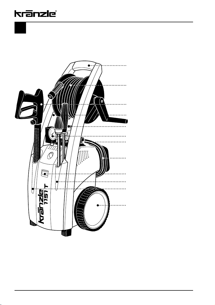
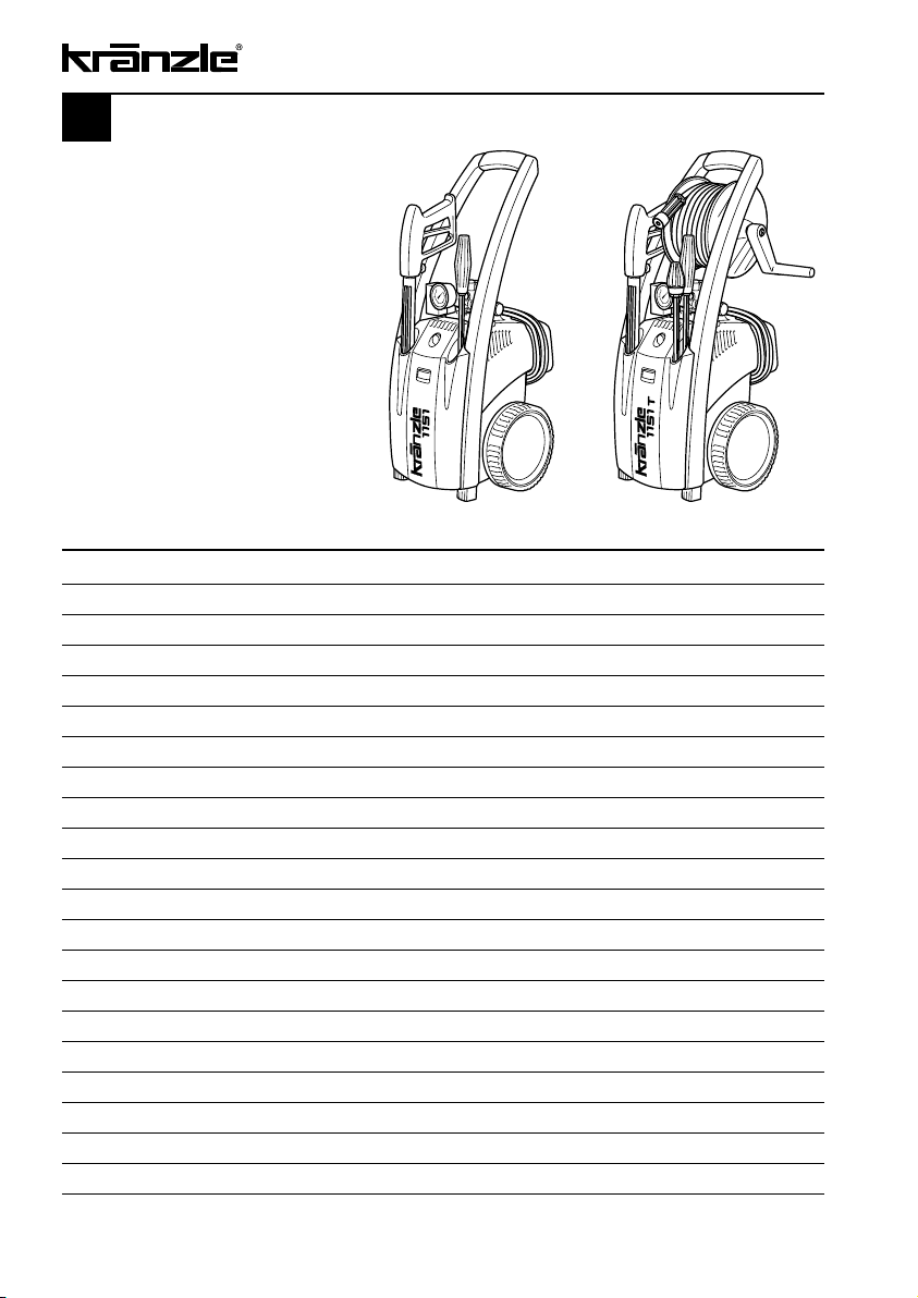
Description of appliance
Kränzle 1151 T, 1151
Ergonomically shaped handle
Hose drum with 15 m steel-weave
high-pressure hose
(1151 T)
High-pressure gun
High-pressure injector for detergents
Special brass pump head
Large stainless steel
manometer
Continuously adj. pressure control
Cable reel with 5 m cable
On/Off switch with motor protection
Receptacle for Vario-Jet lance
and Dirtkiller
Receptacle for high-pressure gun
Integrated trolley takes steps and
rough ground in its stride
Page 3

Contents
Description ................................................................................................................ 2
Contents ................................................................................................................ 3
Technical data ................................................................................................................ 4
Overview “This is what you have purchased” ................................................................. 4
General rules ................................................................................................................ 6
Safety precautions – accident prevention .................................................................. 7
That‘s what you have to observe .............................................................................. 10
Kränzle- technology .................................................................................................... 12
Water and cleaning system .................................................................... 12
Lance and spray gun ............................................................................. 12
Pressure control valve – safety valve .................................................... 12
Motor protecting switch .......................................................................... 13
High pressure hose and spray device ................................................... 13
Total stop system ................................................................................... 13
Putting into operation ................................................................................................. 14
Connection to water mains .................................................................... 14
Direct suction ......................................................................................... 17
When using detergents .......................................................................... 18
To shut down the pump / frost protection ...................................................................... 19
Small repairs – do it yourself! ....................................................................................... 20
EG – Declaration of Conformity .................................................................................... 24
Guarantee .............................................................................................................. 25
Versatile due to Kränzle accessories ............................................................................ 26
Spare parts list ............................................................................................................ 28
Complete assembly ............................................................................... 28
Motor ..................................................................................................... 30
Transmission unit ................................................................................... 32
Valve housing ........................................................................................ 34
Unloader valve and pressure switch ...................................................... 36
Dirtkiller .................................................................................................. 38
Hose drum ............................................................................................. 39
Gun with lance ....................................................................................... 40
Wiring diagram....................................................................................... 41
Inspections – inspection reports ............................................................ 42
Page
3
Page 4
4
Technical data
Operating press. continuously adj. 10 - 130 bar (1900 PSI) 10 - 130 bar (1900 PSI)
Nozzle size 25045 25045
Permissible overpressure 150 bar 150 bar
Water output at 2,800 r.p.m. 10 l/min at 2,800 r.p.m. 10 l/min
Water inlet temperature max. 60 °C max. 60 °C
Suction height 1 m 1 m
Hose drum no yes
Steel-weave high-pressure hose 10 m 15 m
Detergent suction yes yes
Total stop system yes yes
Connected load 230 V~, 12.0 A, 50 Hz 230 V~, 12.0 A, 50 Hz
Power input P 1 - 2.8 kW P 1 - 2.8 kW
Power output P 2 - 2.1kW P 2 - 2.1 kW
Weight 22 kg 26 kg
Dim. incl. pulling handle in mm 300 x 330 x 800 300 x 330 x 800
Sound level acc. to DIN 45 635 88 dB (A) 88 dB (A)
Sound level with Dirtkiller 90 dB (A) 90 dB (A)
Acoustic power LWA 93 dB (A) 93 dB (A)
Recoil at lance approx. 27 N approx. 27 N
Vibration at lance 1.9 m/s
Order no. without Dirtkiller 41.216
Order no. with Dirtkiller 41.216 1 41.215 1
Kränzle 1151 Kränzle 1151 T
2
1.9 m/s
2
Permissible tolerance for figures ± 5 % acc. to VDMA uniform sheet 24411
Page 5
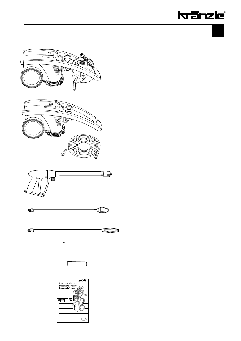
This is what you have purchased
1.
Kränzle high-pressure cleaner 1151 T
with 15 m steel-weave high-pressure hose
and hose drum
or
Kränzle high-pressure cleaner 1151
with 10 m steel-weave high-pressure hose
but without hose drum
2.
Safety spray gun with insulated handle
and screw connection
5
3.
Dirtkiller lance with stainless steel pipe
(not applicable for 41,216)
4.
Vario-Jet lance with stainless steel pipe
5.
Handle with fixing screw for hose drum
6.
Operating manual
Page 6

6
General rules
Range of application
Use machines for cleaning tasks with high-pressure water jet and detergents or with
high-pressure water jet without detergents only.
Inspections
The machine must be inspected according to the “Guidelines for Liquid Spray Devices”
at least once every 12 months by a qualified person, to ensure that continued safe
operation is guaranteed. The results of the inspection are to be recorded in writing. This
may be done in any form. For inspection reports see pages 42-43.
High-pressure cleaners used for commercial purposes have
to be checked by a qualified person at least every 12 months!
Accident prevention
The machine is designed for accidents to be impossible if used correctly. The operator is
to be notified of the risk of injury from hot machine parts and the high pressure water jet.
The “Guidelines for Liquid Spray Devices” must be complied with. (see pages 8 and 9).
Oil change:
The first oil change should be carried out after approximately 50 operating hours. After
that no further oil change will be necessary for the life cycle of the high-pressure
cleaner. If it becomes necessary during repairs, or because the oil has a greyish colour
to perform an oil change, then the oil draining screw should be opened and the oil emptied into a container. The oil is to be caught in the reservoir and disposed of in an approved manner. New oil: 0.25 l - Motor oil: W 15/40.
Oil leakage: If oil leaks contact your nearest after-sales
service (dealer) at once. (Ecological damage, damage to
the transmission)
In case of increased humidity or fluctuations in
temperature development of condensed water is possible;
if the oil turns grey, you must change it.
Page 7
Safety precautions
7
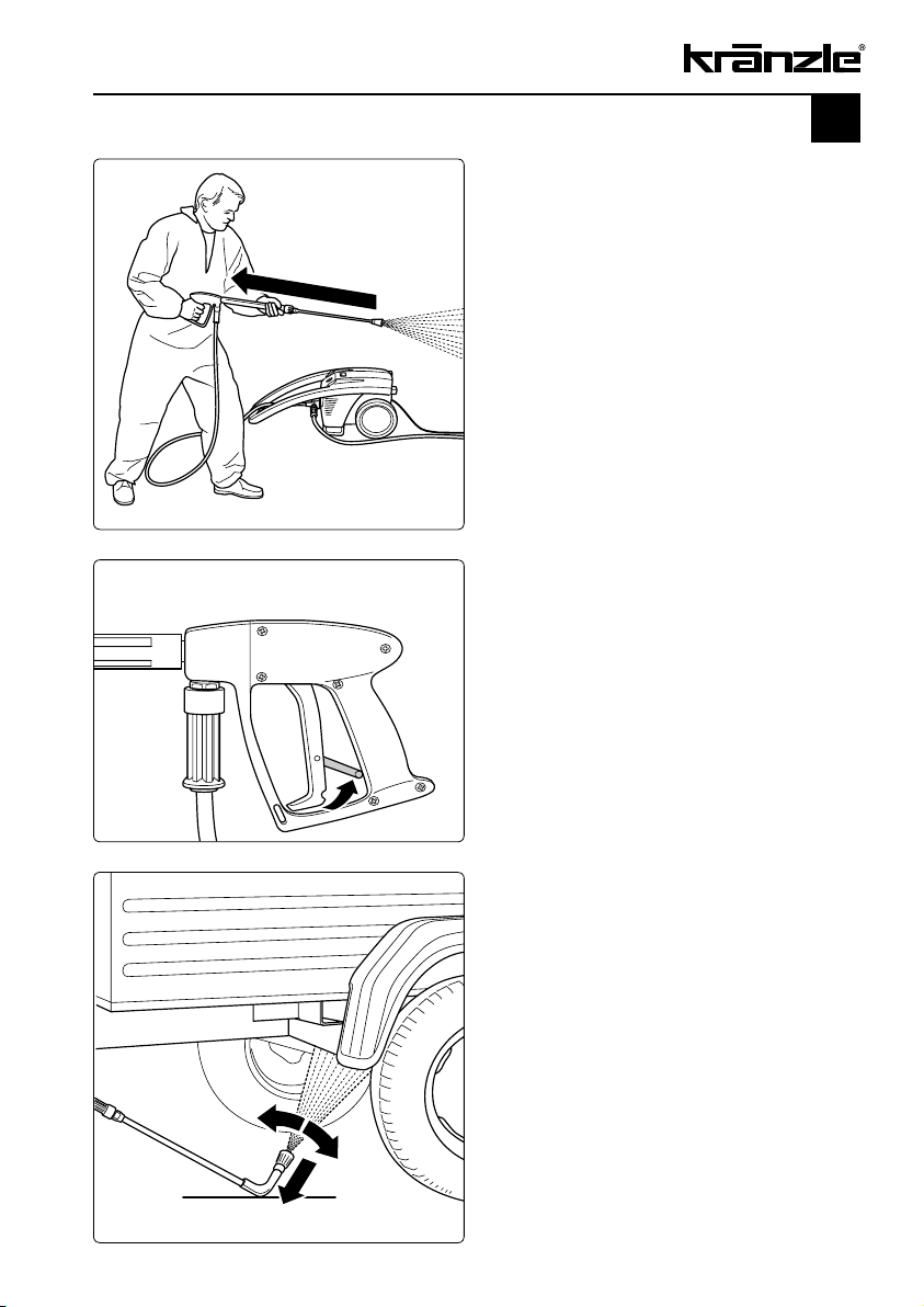
Bear in mind that during cleaning tasks
with a high-pressure water jet a significant
recoil at the lance arises. Please stand
firmly. (see technical data on page 4).
Apply the safety catch on the spray
gun after each use, in order to prevent
unintentional spraying!
Always aim the underbody lance! Bear
in mind when using a curved or angled
spraying lance that there is a significant
amount of torque in the recoil!
Page 8
8
Safety precautions – This is prohibited!
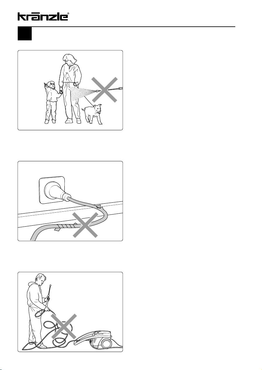
Never direct the water jet at people
or animals!
Only use pow er cables which are
in perfect w orking order! Do not
damage the p ower cable or repair it
incorrectly!
Never pull t he high pressure hose
if it has for med kinks or “ nooses”!
Never pull t he hose over s harp
edges!
Page 9
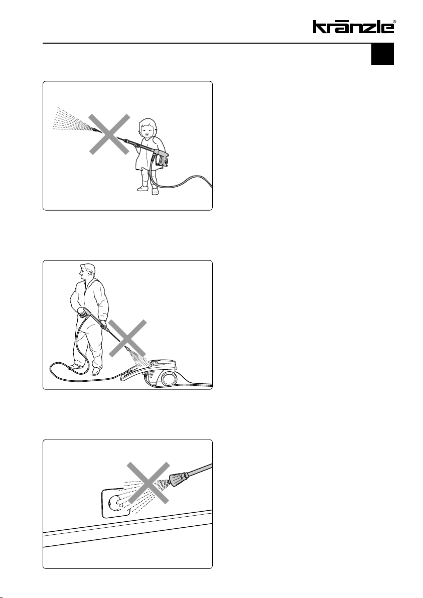
Never allow children to use the high
pressure cleaner!
Never direct the water jet at the
machine itself!
9
The machine may not be placed within
reach of the water jet spray mist!
Never direct the water jet at a power
socket!
Page 10
10
Please note - important:
Lack of water
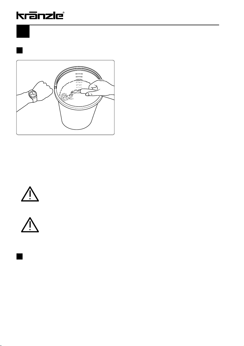
If the metered quantity of water is too small, you have to use a
different water connection, guaranteeing the necessary output.
Lack of water occurs more often than you
probably believe. The more powerful a
high-cleaner is the greater is the danger
that a lack of water occurs. If there is only
an insufficient amount of water available,
cavitation (water-gas mixture) arises inside
the pump, which is normally noticed too late
or even not at all.
The pump will be destroyed!
Please check the available quantity of water
by filling a bucket with litre scale for one
minute
.
A minimum water quantity of 10 litres
per minute must be available to
guarantee a trouble-free operation of the
Kränzle 1151 T/1151.
Lack of water leads to an accelerated wear of the joints
(no guarantee)
Connection to water supply
Please pay attention to the regulations of your waterworks company! In accordance
with DIN EN 61770, the machine may not be directly connected to the public drinking
water supply lines. A brief connection however is permissible according to DVGW
(German Association for Gas and Water Affairs) if a tube ventilator with check valve
(Kränzle order no. 41.016 4) is built into the water supply. Also indirect connection
to the public drinking water supply lines is permissible by way of free emission in
accordance with EN 61 770; e.g. by using a reservoir with a float valve.
Direct connection to a non-drinking water supply line is permissible.
Page 11
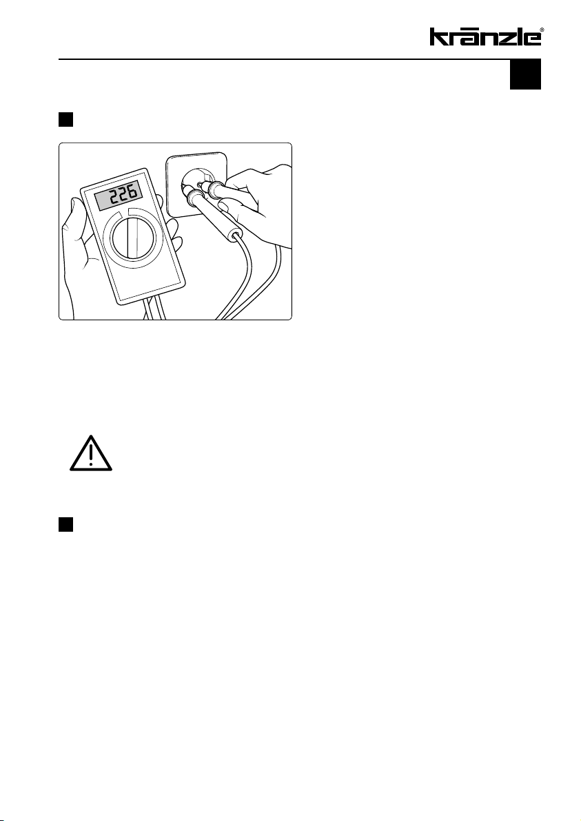
Insufficient quantity of electricity
If there are too many collectors in your
proximity connected to the network at the
same time, the available voltage and the
current intensity may decline.
Consequently the motor of the high-pressure cleaner does not start or even blows.
The power supply may also be insufficient
if the power cable is too long or too thin.
If extension cables are too long, this may
lead to a voltage drop causing
malfunctions or start-up difficulties.
Kränzle 1151 T/1151:
230 V ~, 12,0 A, 50 Hz
Check the line fusing and have the voltage and the available current
intensity checked by an expert in case of uncertainty.
11
Electrical connection
The machine is supplied with an electrical power cable with plug. The mains plug must
be fitted to a standard grounded socket with a 30mA residual current operated device.
The socket must be protected with a 16A delay action fuse on the mains side.
When using an extension cable, this must have an earthed lead which is properly
connected to the socket. The conductors in the extension cable must have a minimum
cross section of 1.5 mm².
Plug connections must be of a spray-proof design, and may not be located on a wet
floor. With extension cables of more than 10 m the minimum cross section must be
2.5 mm! When using a cable drum, always keep the cable wound as far as possible.
Page 12

12
Kränzle technology
Wasser and cleaning system
Water can be connected at mains pressure (1-8 bar pre-pressure) to the high pressure pump or it
can be sucked directly from a storage tank. The water is then forced under pressure by the high
pressure pump to the lance. The high pressure jet is formed by the nozzle at the end of the lance.
Environmental, refuse disposal and water protection
regulations must be observed!
Lance with spray gun
The machine can only be operated when the safety trigger is squeezed. When the
lever is squeezed, the spray gun opens. The liquid is then pumped to the nozzle. The
spray pressure increases and quickly reaches the selected operating pressure. When
the trigger is released, the trigger gun closes and any further spraying of liquid from the
lance is stopped. The pressure gauge must show 0 bar.
The increase in pressure when the trigger gun is closed causes the pressure control
valve-safety valve to open. The motor is switched off by the pressure switch. When
the trigger gun is opened, the pressure control valve - safety valve closes, the motor
is started and the pump resumes pressure spraying from the lance with the selected
operating pressure.
The spray gun is a safety device. Repairs should only
be performed by qualified persons. Should replacement
parts be required, use only components authorized by the
manufacturer.
Pressure control valve - safety valve
The pressure control valve - safety valve protects the machine from a build up of
excess pressure, and is designed not to permit an excess pressure to be selected for
operation. The limit nut on the handle is sealed with a spray coating. The operating
pressure and spray rate can be steplessly adjusted by turning the handle
Replacements, repairs, new adjustments and sealing
should only be performed by qualified persons.
.
Page 13

13
Motor protection switch
The motor is protected from overload by a motor protection switch, which cuts out the
motor in the event of overload. However should the switch trip frequently, the cause of
the malfunction should be located and rectified (see page 11).
Replacements and inspection work should only be
performed by qualified persons when the machine is
disconnected from the power supply, i.e. with plug pulled
out from the electrical socket.
High pressure hose and spray device
The high pressure hose and spraying device supplied with the machine are made of high
grade material, they are also optimized for the machine and marked as required by the
appropriate regulations. (max. hose length 20 m)
If replacement parts are required, only such parts that
are authorized by the manufacturer and which bear the
markings required by the appropriate regulations may be
used. The high pressure hose and spray device must be
connected in a pressure-tight manner (without leakage).
The high pressure hose may not be driven over, pulled
excessively, or twisted.
The hose may under no circumstances be pulled over
sharp edges.
Defective high-pressure hoses must not be repaired (acc. to
DIN 20022) but have to be replaced by new hoses appoved by
the manufacturer.
Total stop system
Kränzle 1151 and 1151 T high-pressure cleaners are equipped with a total stop system. If
the main switch is switched on the motor is started by a pressure switch, as soon as the
gun is operated. If the trigger is released the motor is switched off at once.
Page 14
14
Putting into operation
Setting up – Location
Neither set up or operate the machine in rooms where
there is a risk of fire or explosion nor put it into puddles.
Do not use the machine under water.
1.
Move high-pressure cleaner to the job
site. The Kränzle 1151 T/1151 is a
movable machine with sturdy trolleys
ideally suited for difficult terrain and stairs.
2.
heck water inlet filter for cleanliness
prior to putting the machine into
operation!
Manually unscrew hose attachment. Take
out the serial water inlet filter using needle
nose pliers and clean if filter is soiled.
3
. Each time check oil level at oil-level
glass prior to putting HP cleaner into
operation. (Take care that cleaner is in
horizontal position!)
The oil level must be visible in the oil-level
glass.
4.
1151 T: Put up machine. Release
fixing screw from hexagonal base of
hose drum, put tiltable handle onto the
hexagonal base and fix with screw.
Page 15
15
5.
Push on lance or Dirtkiller lance to
gun.
6.
Screw together lance and gun.
7.
Unwind high-pressure hose straight
and without nooses. (When using hose
extensions take care that the max. length
of 20 m is not exceeded!)
8.
Push on HP hose to gun.
9.
Tightly screw together HP hose and
gun.
Be careful when using hot water!
When running your high pressure cleaner with hot water
of 60° C raised temperatures occur. Do not touch the
metal parts of the cleaner without safety gloves!
Page 16

16
Putting into operation
10.
Connect water hose to water inlet.
The cleaner may be connected to a water
mains (1-8 bar pre-pressure) with either
cold or up to 60°C warm water.
11.
Connect to circuit.
Kränzle 1151 T/1151:
230 V ~, 12.0 A, 50 Hz
The socket must be protected with a 16A
delay action fuse on the mains side.
12.
Steplessly adjust operating pressure
with handwheel. The maximum pressure
is adjusted ex work.
Kränzle 1151 T/1151: max. 130 bar
13.
Put HP cleaner into horizontal position.
These machines must be operated in
horizontal position!
Deaeration of the appliance: Pull and
release the trigger several times.
Switch on high-pressure cleaner with
opened spray gun. Start cleaning task.
Page 17

Direct suction
17
Sucking in water from ponds, rain butts etc.
Due the suction capacity of its pump (up to 1.0 m suction height, max. hose length 2 m)
this high-pressure cleaner can suck in water for cleaning purposes from separate
containers or ponds.
Prior to starting the first suction the pump resp. the
suction hose has to be filled with water!
Attach suction hose. The inner diameter of
the hose must be at least 1/2“ = 12.7 mm.
Best use suction hose with suction filter
from the Kränzle accessories:
Order no. 15.038 3
Use clean water only!
Page 18

18
Suction of detergents
When using cleansing agents
Suction of cleansing agents by means of the detergent injector is only possible if the
Vario Jet lance is fitted. The lance mus be set to low pressure.
1.
Please chemicals filter into container
with cleansing agent.
2.
To reach the low pressure push Vario
nozzle to the front so that the injector can
suck in the cleansing agent.
3.
The chemicals supply is automatically
stopped when closing the Vario nozzle by
pushing it backwards.
Let cleansing agent take effect and then
spray off with a high-pressure jet.
Observe specifications of detergent manufacturer!
e.g.: protective equpment, rules for waste water treatment etc.
Caution: dissolvents!
Never suck in liquids containing solvents like varnish solvents, petrol, oil or similar liquid! Observe specifications
of detergent manufacturers! Seals inside the appliance
are no resistant against solvents! The spray mist of
solvents is highly inflammable, explosive and poisonous.
Page 19

To shut down the pump
01.
Switch off the machine
02. Cut off the water supply
03. Open the spray gun briefly until the pressure is released
0
4. Apply the safety catch on the spray gun
05. Remove the water hose and spray gun
06. Drain the pump: switch on the motor for approx. 20 seconds
0
7. Pull the plug from the socket
08. Clean HP hose and wind up
09. Clean power cable and wind up
10. Clean water filter
11. Winter: store the pump in rooms above 0°C
19
Store in a place-saving manner
Due to their compact and space saving
design the Kränzle 1151 T/1151 cleaners
can be stored practically anywhere.
Page 20

20
Small repairs -
do it yourself!
No water from the nozzle but the gauge shows full pressure:
Most likely the nozzle is blocked.
The pressure gauge shows full pressure,
but from the nozzle comes only little water
or no water at all.
(Inside the pressure gauge is no water but
a filling with glycol to damp the vibration of
the pointer.)
Proceeding:
Switch off the cleaner. Pull plug from
the socket. Operate gun seveal times to
decrease the pressure.
First unscrew gun and lance, then rinse
hose from any residues.
Check water inlet filter for soiling.
If the problem still exists, take wire (paper
clip) and push through nozzle opening.
If this procedure is not successful, the nozzle has to be dismantled and cleaned or even
replaced, if necessary.
CAUTION! Pull plug from socket prior to starting
any repair work!
Page 21

Pressure gauge shows little pressure, the water from the nozzle comes
in squirts: Most likely the valves are soiled or sticky.
The pressure gauge shows little pressure
despite fully turned up pressure regulation.
The water from the lance comes in squirts.
The HP hose vibrates.
(Inside the pressure gauge is no water but
a filling with glycol to damp the vibration of
the pointer.)
Proceeding:
Unscrew all 6 valves, one after the other
(hexagonal brass screws, 3 in a row,
vertically and horizontally)
21
Take out valve body (with green or red
plastic coating) and O-ring by means of
needle nose
pliers. Check O-ring for damage. In
case of a damage the O-ring has to be
replaced.
Take a wire (paper clip) and clean
valves under running water.
Do not forget the O-ring during
reassembly!
Page 22

22
Small repairs -
do it yourself!
The pressure gauge shows full pressure although the gun has
been closed. The pressure switch valve switches constantly.
Possible cause no.1: Leakage
Having closed th gun, the HP cleaner must
shut down and the pressure gauge must
show „0“ bar.
If the pressure gauge still shows full pressure and the motor constantly switches on
and off, the possible reason for this can be
a leakage of the pump, the HP hose or the
lance.
Proceeding:
Check the connections from the HP cleaner to the the HP hose, from the hose to
the gun and also the connection between
lance and gun for tightness.
Switch off the cleaner. Shortly press the
trigger of the gun to decrease the pressure.
Unscrew HP hose, gun and lance and
check the O-rings.
If the O-rings are damaged they have to
be replaced.
In case of a leakage there is no guarantee for possible
consequential damages.
Page 23

The pressure gauge shows full pressure although the gun has
been closed. The pressure switch valve switches constantly.
Possible cause no. 2: The non-return valve is soiled or defective.
Proceeding:
Switch off machine and pull plug from
socket. Stop water supply. Unscrew pump
outlet.
Take out check ball and check for soiling
or damage of ball or stainless steel seat
inside the pump housing.
23
Replace non-return valve if necessary.
There is no guarantee if the pump is damaged by
defective O-rings due to air induction or lack of water
(cavitation).
Page 24

24
EC declaration of conformity
Hereby we declare that:
Kränzle 1151 T, Kränzle 1151
technical specifications available from:
comply with the following guidelines
and their amendments for high-pressure
cleaners:
Sound level measured:
Sound level guaranteed:
Applied conformity evaluation procedures
Applied specifications and standards:
Manfred Bauer, Fa. Josef Kränzle
Rudolf-Diesel-Str. 20, 89257 Illertissen
machinery directive 2006/42/EEC,
EMC-directive 2004/108 EEC,
noise directive 2005/88/EC, Art. 13,
HP water spraying machines
annex 3, part B, chapter 27
91 dB (A)
93 dB (A)
annex V, noise directive 2005/88/EC
EN 60 335-2-79 :2004
EN 55 014-1 :2006
EN 61 000-3-2 :2006
EN 61 000-3-3 :2008
I. Kränzle GmbH
Elpke 97 D - 33605 Bielefeld
Bielefeld, 21.12.2010
(Managing director)
Page 25

Guarantee
The guarantee is only valid for material and manufacturing errors.
Wearing does not fall within this gurantee.
The instructions in our operating manual must be complied with..
The operating instructions form part of the guarantee. The Guarantee is void if other parts
are used than genuine Kränzle accessory parts or genuine Kränzle spare parts.
For high-pressure cleaners sold to the user the guarantee period is 24 month.
For high-pressure cleaners sold for industrial use the guarantee period is 12 month.
In the case of a guarantee please contact your dealer or authorized seller delivering
accessories and your purchase receipt. You can n them in the internet under
www.kraenzle.com.
The guarantee is also void if the machine is used with exceeding the temperature and
speed limits, a voltage below the required rating, with less than the required amount of
water or with dirty water.
Pressure gauge, nozzle, valves, sleeves, high pressure hose and spray equipment are
wear parts and are not covered by the warranty.
25
Page 26

26
Versatile due to Kränzle accessories
Rotating washing brush with 400 mm
extension, Order no. 41 050 1
Floor cleaning appliance
round cleaner UFO, Order no. 41.850
Dirtkiller lance
(rotating point jet nozzle with intensive
cleaning effect)
Order no. 41.072 5
Page 27

Retrofit kit for hose drum
with 15 m high-pressure hose
Order no. 40.184 2
27
Suction hose with intake filter
Order no. 15.038 3
Spray guard
Order no.41.052
Page 28

28
Spare parts list
Complete assembly
Kränzle 1151 T/1151
Page 29

Kränzle 1151 T/1151 - Complete assembly
No Description Qty. Ord.-No
2 Fahrgestell 1 44.502
3 Frontplatte „ K 1151 „ 1 44.503 7
3.1 Frontplatte „ K 1151 T „ 1 44.503 6
4 Köcher groß 1 44.506
5 Köcher klein 1 44.507
6 Knickschutz 1 44.509
7 Rad 2 44.538
8 Radkappe 2 45.200 8
9 Kabelhalteplatte 1 44.505
10 Achse 2 44.504
11 Netzanschlusskabel 1 41.092
12 Chemikaliensaugschlauch mit Filter 1 15.038
13 Versteifungsplatte 1 44.511
15 Kunststoffsenkschraube 5,0 x 20 2 45.421 1
16 O-Ring 9,3 x 2,4 2 13.273
17 Kunststoffschraube 5,0 x 20 20 43.018
18 Auagepuffer 2 44.510
19 Kunststoffschraube 5,0 x 30 2 43.418
20 Scheibe 40 x 6 x 1,5 (Stahl) 2 45.216 7
21 Unterlegscheibe 8,4 4 50.186
22 Innensechskantschraube M 8x 30 4 41.036 1
23 Kunststoffschraube 4,0 x 16 2 43.417
24 Kunststoffschraube 5,0 x 50 2 41.411
25 Kunststoffschraube 5,0 x 70 2 44.519
26 Kunststoffschraube 3,5 x 14 2 44.525
27 Anschlussleitung Schlauchtrommel 1 44.520
28 Midi-Pistole 1 12.160
29 Vario-Jet 042 kpl. mit Lanze 1 41.156 5-042
30 Schmutzkiller 042 1 41.571-042
31 Kabelklemme 1 43.431
32 Schraube 3.5 x 16 2 44.161
33 Griffabdeckung 1 44.535
34 Gummipuffer links+rechts 1 44.536
35 Rad kpl. (7, 8, 10, 15, 20) 2 44.538 2
37 HD-Schlauch NW 6 10 m (K1151) 1 43.416
37.1 HD-Schlauch NW 6 15 m (K1151 T) 1 40.170
38 O-Ring 9,3 x 2,4 2 13.273
29
Page 30

30
Spare parts list
Motor
Kränzle 1151 T/1151
Page 31

Kränzle 1151 T/1151
- Motor
No Description Qty. Ord.-No
1 Ölgehäuse mit Dichtung, Deckel
Öldichtung, Schulterlager 1 44.501
2 Motorgehäuse mit Stator 1 23.002 4
3 Motorwelle mit Rotor 1 43.024
4 Passfeder 6 x 6 x 20 1 41.483 1
5 Motor-Lager B-Seite Z-Lager 1 43.025
6 Motor-Lager A-Seite Schulterl. 1 43.026
7 Schelle für Lüfterrad 1 44.534 1
8 Öldichtung 25 x 35 x 7 1 41.024
9 Lüfterrad 1 44.534
10 Lüfterhaube 1 41.497
11 Flachdichtung 1 44.513
12 Lüsterklemme 3-pol. 1 43.031 2
13 Schaltkasten 1 44.508 3
14 Schalter mit 12 A-Überstromauslöser 1 43.033
15 Klemmrahmen mit Schalterabdichtung 1 43.453
16 Kabelverschraubung PG 11 2 41.419
17 Gegenmutter PG 11 2 44.521
18 Kondensator 40 µF 1 43.035
19 Netzkabel für 230V / 50/60Hz 1 41.092
20 Blechschraube 3,5 x 9,5 2 41.088
21 Blechschraube 2,9 x 16 1 43.036
22 Innensechskantschr. M 5 x 12 4 40.134
23 Innensechskantschr. M 5 x 30 4 42.130
24 Erdungsschraube kpl. 1 43.038
25 Deckel für Schaltkasten 1 44.512
26 Dichtung für Deckel 1 44.522
27 Kunststoffschraube 5,0 x 20 4 43.018
28 Blechschraube 3,9 x 13 3 41.078
29 Toleranzhülse 1 43.063 1
31
40 Motor 230V / 50 Hz komplett mit Ölgehäuse 1 44.530
und Lüfterrad, ohne Elektrik
41 Schaltkasten komplett 1 44.560
Page 32

32
Spare parts list
Transmission unit
Kränzle 1151 T/1151
Page 33

Kränzle 1151 T/1151 - Transmission unit
No Description Qty. Ord.-No
1 Gehäuseplatte 1 43.003
2 Öldichtung 14 x 24 x 7 3 41.631
3 O-Ring 83 x 2 1 43.039
4 Plungerfeder 3 43.040
5 Federdruckscheibe 14 mm 3 43.041
6 Plunger 14 mm 3 43.005
7 Sprengring 14 mm 3 41.635
8 Taumelscheibe 9,25° 1 41.028-9,25
10 Axial-Rillenkugellager 3-teilig 1 43.486
12 Innensechskantschraube M 8 x 25 4 40.053
13 Verschlussschraube M 18 x 1,5 1 41.011
14 O-Ring 14 x 2 3 43.445
15 Ölschauglas 1 42.018 1
16 Ölverschlussschraube rot 1 43.437
17 Dichtung Öldeckel 1 44.501 1
18 Deckel Ölgehäuse 1 44.501 2
19 Innensechskantschraube M 5 x 12 4 41.019 4
33
Page 34

34
Spare parts list
Unloader valve and pressure switch
Kränzle 1151 T/1151
Page 35

Kränzle 1151 T/1151 - Unloader valve and pressure
switch
No Description Qty. Ord.-No
7 O-Ring 12 x 2 2 15.005 1
8 O-Ring 11 x 1,5 1 12.256
9 Edelstahlsitz 1 14.118
10 Sicherungsring 1 13.147
11 Edelstahlkugel 8,5 mm 1 13.148
12 Edelstahlfeder 1 14.119
13 Verschlussschraube 1 14.113
14 Steuerkolben 6 mm für AZ mit Dichtungen 1 44.532
15 Parbaks für Kolben 14 mm 1 14.123 1
16 Parbaks für Spindel 6 mm 1 14.123 2
17 MS-Scheibe 1 43.045
18 Kolbenführung 6 mm 1 14.130 1
19 Mutter M 6 2 14.127 1
20 Feder schwarz für AZ-Pumpe 1 43.046
21 Federdruckscheibe 1 43.047
22 Kugellager 1 43.048
23 Handrad M 6 für AZ-Pumpe 1 43.049
24 Mutter M 6 mit SW 8 1 43.010
25 Kappe für Handrad AZ-Pumpe 1 43.050
26 Manometer 1 15.039
49 Druckfeder 1 x 8,6 x 30 1 40.520
50 O-Ring 3,3 x 2,4 1 12.136
51 Führungsteil Steuerstößel 1 15.009 1
52 O-Ring 13 x 2,6 1 15.017
53 O-Ring 14 x 2 1 43.445
54 Parbaks 4 mm 2 12.136 2
55 Stützscheibe 2 15.015 1
56 Edelstahlfeder 1 15.016
57 Steuerstößel lang 1 15.010 2
58 Parbaks 7 mm 1 15.013
59 Stopfen M10x1 (durchgebohrt) 1 13.385 1
60 Gehäuse Elektroschalter 1 15.200
61 Gummimanschette 1 15.202
62 Sechskant-Mutter M 4 2 12.138
63 Überwurfmutter PG 11 1 15.203
64 Kabel 2 x 1,5 mm² 1 44.552
65 Blechschraube 2,8 x 16 6 15.024
66 Deckel Elektroschalter 1 15.201
67 O-Ring 44 x 2,5 1 15.023
68 Mikroschalter 1 15.018
69 Zylinderschraube M 4 x 22 2 15.025
35
70 Steuerkolben kpl. m. Handrad 44.532 1
71 Rep.-Satz Druckschaltermechanik 15.009 3
72 Druckschalter kpl. ohne Mechanik 44.561
73.1 Ventilgehäuse kpl. für K1151 44.562
73.1 Ventilgehäuse kpl. für K1151 T 44.563
Page 36

36
Spare parts list
Valve housing
Kränzle 1151 T/1151
Page 37

Kränzle 1151 T/1151 - Valve housing
No Description Qty. Ord.-No
1 Ventilgehäuse 1 44.550
2 Ventilstopfen 5 41.011
3 Ventilstopfen mit R1/4“ IG 1 41.011 1
4 Ventile (rot) 6 41.612
5 Dichtstopfen M 8 x 1 3 13.158
6 Dichtstopfen M 10 x 1 1 43.043
7 O-Ring 12 x 2 12 15.005 1
8 O-Ring 11 x 1,5 1 12.256
9 Edelstahlsitz 1 14.118
10 Sicherungsring 1 13.147
11.1 Edelstahlkugel 10,0 mm 1 12.122
26 Manometer 1 15.039
27 Stützring 3 43.091
28 Gewebemanschette 14x24x5 3 41.613 1
29 Backring 14 x 24 3 41.614
30 O-Ring 26 x 2 3 43.052
31 Leckagering 3 43.053
32 Manschette 14 x 20 x 4/2 3 43.054
33 Zwischenring mit Abstützung 3 43.055
34 Rückschlagfeder 1 14.120 1
35 Ausgangsst. Inj. ST30 M22x1,5 (K1151) 1 44.544
incl. , 2x37, 2x38, 39, 40, 41, 52
35.1 Verschlussstopfen für Kugelrücks.v. (K1151 T) 1 44.524
36 Verschlusstopfen 1/4“ (K1151) 1 13.181
36.1 Ermetowinkel R1/4”x8 (K1151 T) 1 40.179
37 Verschlussschraube M10x1 1 13.385
38 O-Ring 6x1,5 2 13.386
39 Saugzapfen Schlauchanschluss 1 13.236
40 Edelstahlkugel 5,5 mm 1 13.238
41 Edelstahlfeder 1 13.239
42 Innensechskantschr. M 8 x 25 2 40.053
43 Innensechskantschr. M 8 x 40 2 43.059
44 Dichtring Kupfer 1 14.149
45 Sauganschluss 1 41.016
46 Wasserlter 1 41.046 2
48 Gummi Dichtring 1 41.047 1
49 Steckkupplung 1 41.047 2
50 O-Ring 1 41.047 3
51 Alu-Dichtring 1 13.275
52 O-Ring 18 x 2 1 43.446
37
60 Repair kit valves 41.648
61 Repair kit sleeves 43.060
Page 38

38
Spare parts list
Hose drum
Kränzle 1151 T/1151
Page 39

Kränzle 1151 T/1151 - Hose drum
No Description Qty. Ord.-No
1 Schale groß 1 40.160
2 Schale klein 1 40.161
3 Knickschutz 1 40.162
4 Antriebswelle 1 44.517
5 Kurbel klappbar 1 48.108
6 Lagerklotz links 1 44.515
7 Lagerklotz rechts 1 44.516
8 Drehgelenk 1 40.167
9 Achse mit Wasserführung 1 44.518
10 Eingangsinjektror 1 40.169
11 HD-Schlauch NW 6 15 m 1 40.170
12 Schraube M 6 x 16 1 40.171 1
13 Schraube M 5 x 10 1 43.021
14 Anschlussrohr Ermeto Edelstahl 1 44.520
15 Parbaks 16 mm 2 13.159
16 O-Ring 10 x 2 1 43.068
17 Sicherungsring 16 mm 1 40.182
18 Scheibe MS 16 x 24 x 2 1 40.181
19 O-Ring 6,68 x 1,78 1 40.585
20 Mutter M18 x 1 1 40.185
21 Kunststoffschraube 5,0 x 20 4 43.018
22 Zahnscheibe 6,4 1 40.183
23 Scheibe DIN9021 6,4 1 50.174
25 Saugzapfen Schlauchanschluss 1 13.236
26 Edelstahlkugel 5,5 mm 1 13.238
27 Edelstahlfeder 1 13.239
28 Chemikaliensaugschlauch mit Filter 1 15.038
29 O-Ring 6 x 0,8 2 40.177
39
Page 40

40
Spare parts list
Gun with lance
Kränzle 1151 T/1151
Page 41

Kränzle 1151 T/1151 - Gun with lance
No Description Qty. Ord.-No
5 Rohranschlussteil R1/4“ 1 12.125
incl. Pos. 3, 4, 21
6 Scheibe 5,3 DIN9021 1 50.152
7 Abzug-Hebel kpl. 1 12.144 1
15 Rohr kunststoffumspritzt 1 15.004 2
bds. R 1/4“ AG
16 Überwurfmutter ST 30 M22 x 1,5 IG 1 13.276 1
17 Außen-Sechskant-Nippel R 1/4“ IG 1 13.277 1
18 O-Ring 9,3 x 2,4 1 13.273
19 ST 30-Nippel M 22 x 1,5 1 13.363
20 Rohr 400 lang, bds. M12 x 1 1 15.002
21 Aluminium Dichtring 6 13.275 1
30 Klemmstück 1 41.155 2
31 Halterung für Klemmstück 1 41.155 4
32 Kunstoffhülle 1 41.155 1
33 Vario-Jet 042 1 41.155 6
A Rep.-Kit 12.158
Pos: 3, 4, 5, 8, 9,10, 12, 15, 21
B Griff komplett 12.164
Midi-Pistole kpl. 12.160
41
Lanze kpl. mit Vario-Jet 042 41.156
Page 42

42
Spare parts list
Kränzle 1151 T/1151
Dirtkiller (special accessories)
No Description Qty. Ord.-No
1 Sprühkörper 1 41.520
2 O-Ring 6,88 x 1,68 1 41.521
3 Düsensitz 1 41.522
4 Düse 042 1 41.523-042
5 Stabilisator 1 41.524
6 O-Ring 1 40.016 1
7 Sprühstopfen 1 41.526
8 Rohr 400 mm 2x M 12 x 1 1 41.527
9 ST 30-Nippel M 22 x 1,5 / M 12 x 1 ISK 1 13.363
11 Kappe vorn für Schmutzkiller 1 41.528 1
12 Kappe hinten für Schmutzkiller 042 1 41.540 2
Rep.-Satz Schmutzkiller 042 41.096 5
bestehend aus je 1x 2; 3; 4; 5
Schmutzkiller 042 kpl. mit Lanze 41.571-042
Page 43

Wiring diagram
C: 40 µF
Terminal strip
Motor stator
Kränzle 1151 T/1151
Weber-Unimat WT 22 - 551
8.5 A Excess current release
43
Page 44

44
Inspection report for HP cleaners
HP cleaners for industrial use have to be checked by an expert every 12 months!
Inspection report on annually carried out Labour Safety Inspection (UVV) according to
the Guidelines for Liquid Spray Equipment. (This inspection sheet serves as proof for
the completion of the retest and must be kept carefully!)
Owner:
Address:
Type:
Serial no.:
Kränzle test seals: Order no. UVV200106
Rep. order no.:
Scope of inspection o.k. yes no repaired
Type plate (on hand)
Operating manual (on hand)
Protective covering, -device
Pressure line (tightness)
Pressure gauge (function)
Float valve (tightness)
Spraying device (marking)
HD-hose / connector (damage, marking)
Safety valve opens at 10 % / 20 % exceeding of operang pr.
Power cable (damage)
Protective conductor (connectedt)
On / Off switch
Used chemicals
Allowed chemicals
Inspection data determined value set value
High-prsure nozzle
Operating pressure..................bar
Switch off pressure................bar
Conductor reist. not exceeded / value
Insulation
Leakage current
Gun locked
Inspection result (tick)
The appliance was checked by an expert according to the Guidelines for Liquid
Spray Equipment, the defects found have been rectified so that the Labour Safety can
be confirmed.
The appliance was checked by an expert according to the Guidelines for Liquid
Spray Equipment. The Labour Safety cannot be confirmed unless the defects found are
rectified by repair or replacement of the faulty parts
The next retest according to the Guidelines for Liquid Spray Equipment has to be carried
out by: Month Year
Place, date Signature
Page 45

Inspection report for HP cleaners
45
HP cleaners for industrial use have to be checked by an expert every 12 months!
Inspection report on annually carried out Labour Safety Inspection (UVV) according to
the Guidelines for Liquid Spray Equipment. (This inspection sheet serves as proof for
the completion of the retest and must be kept carefully!)
Owner:
Address:
Type:
Serial no.:
Kränzle test seals: Order no. UVV200106
Rep. order no.:
Scope of inspection o.k. yes no repaired
Type plate (on hand)
Operating manual (on hand)
Protective covering, -device
Pressure line (tightness)
Pressure gauge (function)
Float valve (tightness)
Spraying device (marking)
HD-hose / connector (damage, marking)
Safety valve opens at 10 % / 20 % exceeding of operang pr.
Power cable (damage)
Protective conductor (connectedt)
On / Off switch
Used chemicals
Allowed chemicals
Inspection data determined value set value
High-prsure nozzle
Operating pressure..................bar
Switch off pressure................bar
Conductor reist. not exceeded / value
Insulation
Leakage current
Gun locked
Inspection result (tick)
The appliance was checked by an expert according to the Guidelines for Liquid
Spray Equipment, the defects found have been rectified so that the Labour Safety can
be confirmed.
The appliance was checked by an expert according to the Guidelines for Liquid
Spray Equipment. The Labour Safety cannot be confirmed unless the defects found are
rectified by repair or replacement of the faulty parts
The next retest according to the Guidelines for Liquid Spray Equipment has to be carried
out by: Month Year
Place, date Signature
Page 46

46
Notes
Page 47

Notes
47
Page 48

I . K r ä n z l e G m b H
E l p k e 9 7
D - 3 3 6 0 5 B i e l e f e l d
R e pr i nt o n l y a l l o w e d w i t h t h e a u t h o r i s a t i o n o f K r ä n z l e .
E f fe c ti v e 0 9 t h o f D e c e m b e r 2 0 1 0
S u b j e c t to te c h n i c a l m od i f ic a t io n s . O rd e r n o : 3 0 . 78 0 1
 Loading...