

Page 1

www.kraenzle.com
1+1
D
GB
F
Original-Betriebsanleitung
Operating manual
Manuel d‘utilisation
Page 2

18
Technical data
Dear customer,
We would like to congratulate you on the purchase of your new hand pushed
sweeper and thank you for your confidence in our products!
You are now the owner of a robust, reliable and easy to handle sweeping
machine – an absolute quality product!
Highest precision and dimensional accuracy in addition to a technology package
consisting of a multitude of details mark the dierence when it comes to
performance, safety and durability.
In order to facilitate handling of the machine, the following pages are intended
to further explain the use of the Kränzle 1+1.
Technical data
Hand powered sweeper
Kränzle 1+1
Width without side broom
720 mm
Width with side broom
790 mm
Height with handlebar, handlebar high/low position 1060/900 mm
Height with folded handlebar 390 mm
Lenght with folded handlebar with side broom 1030 mm
Lenght without side broom, handlebar high/low position 1260/1080 mm
Lenght with side broom, handlebar high/low position 1510/1330 mm
Weight (operating, incl. side broom) 25 kg
Drive wheels (diameter/width) 280 x 40 mm
Swept width without side broom 480 mm
Swept width with side broom 670 mm
Broom roller diameter 250 mm
Broom roller width 480 mm
Min. diameter of roller broom 180 mm
Side broom (Polyester), diameter 325 mm
Side broom drive (Vee belt)
8 x 1765 + - 5
Dirt hopper (40 litres capacity) 25 - 28 l usable
Surfacing rating (theoretic) at 4 km/h with side broom 2.680 m
2
/h
Page 3

19
Contents
Technical data ....................................................................18
Contents ............................................................................19
Description of hand powered sweeper .............................. 20
Safety precautions .............................................................21
General rules ......................................................................22
Putting into operation - Assembly ......................................23
Operation ...........................................................................25
Side broom ........................................................................ 29
Maintenance ...................................................................... 31
Warranty ............................................................................ 33
Spare parts list .................................................................. 50
GB
Operating manual!
Read and conform safety instructions before use!
Keep instructions in a safe place for later use and pass them
on to any future user.
Page 4

20
1
2
3
4
5
6
7
Design
1 Economically shaped handle bar
providing a secure grip
2 Handle for easy lifting of hopper
3 40 liter hopper
4 Handwheel for side broom
adjustment
5 Large natural rubber coated wheels
for safe operation
6 Swivel castors
7 Side broom
Description of hand powered sweeper
Highest sweeping performance due to
dustpan principle.
Page 5

21
Safety precautions
Prior to initial operation, make sure to check unit including working gear for
general state and operability. The machine must not be operated unless in
perfect working order.
The machine operator is required to ensure that the machine is used for its intended purpose and to comply with local conditions during operation, and that no
injury is caused to any third person during its use – in this conjunction, particular
attention is to be paid to children!
This machine must not be operated by persons (including children) with limited
physical, sensory or mental aptitude or lack of experience and/or knowledge unless they are supervised by a person responsible for their safety or have received
instructions from this person as to how the device is used. The sweeping machine must not be used or played with by children or operated by non-instructed
persons.
The machine is not intended for sweeping fluids or burning or glowing objects
such as cigarettes, matches or the like.
Sweeping of explosive fluids, flammable gases, undiluted acids or solvents is
forbidden. This includes gasoline, paint thinners or heating oil which are liable
to produce explosive vapors or mixtures due to air turbulences.
Materials such as acetone, undiluted acids and solvents must not be swept up
because of their agressivness to the machine.
Toxic, carcinogenic or flammable substances such as arsenic, asbestos, barium,
baryllium, lead, pesticides or any other hazardous substances must not be
swept up.
Make sure to use firm gloves when removing glass, metal or other pointy or
sharp edged materials from the dirt hopper.
GB
Page 6

22
General rules
Intended Use
The Kränzle 1+1 hand pushed sweeper is exclusively intended for ordinary
sweeping of surfaces such as production areas, warehouses, parking spaces and
pedestrian crosswalks for sweeping up dry and moist refuse.
Any other use above and beyond is considered as improper use; the manufacturer
shall not be responsible for any damages resulting from any such improper use.
Intended use shall also include compliance with manufacturer
specified maintenance intervals.
The hand pushed sweeper is intended for use on flat surfaces.
With the side broom pressed down, you can easily push the machine across the
area to be cleaned. This should be done at normal sliding speed (approx. 3 km/h).
The sweeping performance depends on the rev speed of the sweeping machine
and consequently on the speed at which the machine is pushed over the surface.
Depending on the type of surface, the required push force ranges between 3 – 3.5 kg.
If the machine is to be moved over longer distances without sweeping, make
sure to pull it backwards. The sweeping functions will be disabled due the
integrated freewheel.
The machine must not be used to remove hazardous dusts.
Acceptance of Machine
Make sure to check the machine after its arrival for any potential transportation
damage. This will be compensated on condition that you have the damage
certified by the forwarding agent.
Page 7
23
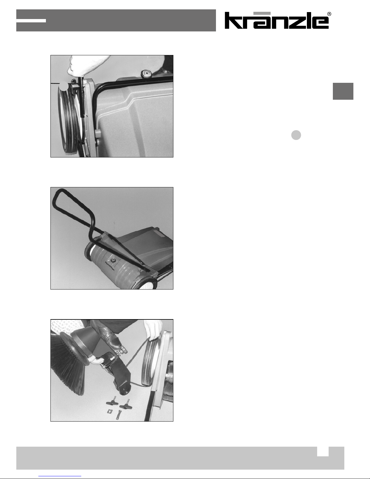
Putting into operation - Assembly
For reasons of packaging, handlebar
and side boom arm, to include broom
and Vee belt are not assembled. After
unpacking the Kränzle 1+1, first
assemble the handlebar and the side
broom next.
1. Bolt handlebar to both sides of the
housing, use the wing bolts .
Note: The handlebar can be mounted
in two positions, as suitable for the
operator´s tallness.
For short people: Install the handlebar
with handle rod bent to downside.
For average and bigger tallness: Install
the handlebar with handle rod bent to
the top end.
2. Unpack side broom arm and broom.
Plug side broom on broom shaft and
secure with bolt; use 10 mm spanner
size. Do not overtorque bolt to avoid
damage to the broom hub. Place the
Vee belt in the pulley overthe RH wheel.
side broom will have to rotate CCW
when machine moves forward
(top view).
Inbetriebnahme
Zusammenbau
Holmanbau
Aus Verpackungsgründen sind der
Holm sowie der Seitenbesenarm
einschließlich Seitenbesen und
Keilriemen nicht montiert. Nach dem
Auspacken der KRÄNZLE 1+1
einschließlich der Holm-Befestigungs-
teile ist zunächst der Holm, dann der
Seitenbesenarm anzubauen.
Holm mit den Flügelschrauben
(A/1) links und rechts am Gehäuse
anschrauben.
Hinweis: Der Holm läßt sich in zwei
Stellungen, abgestimmt auf die
Körpergröße des Bedienungsperso-
nals, montieren.
Für kleine Körpergrößen: Holm mit
Griffstange nach unten abgebogen
montieren.
Für mittlere und große Körper-
größen: Holm mit Griffstange nach
oben abgebogen montieren.
A
Seitenbesenanbau
Seitenbesenarm und Seitenbesen
aus der Verpackung entnehmen.
Seitenbesen auf die Besenwelle auf-
stecken und mit Halteschraube be-
festigen. Schlüsselweite: 10 mm.
(Halteschraube nur leicht anziehen,
so daß die Besennabe nicht ge-
quetscht wird.
Keilriemen über das rechte Rad in
die Nut der Riemenscheibe so
einlegen, daß der Seitenbesen bei
Vorwärtsfahrt gegen den Uhrzeiger-
sinn dreht (von oben gesehen).
Inbetriebnahme
1
1
GB
Page 8
24
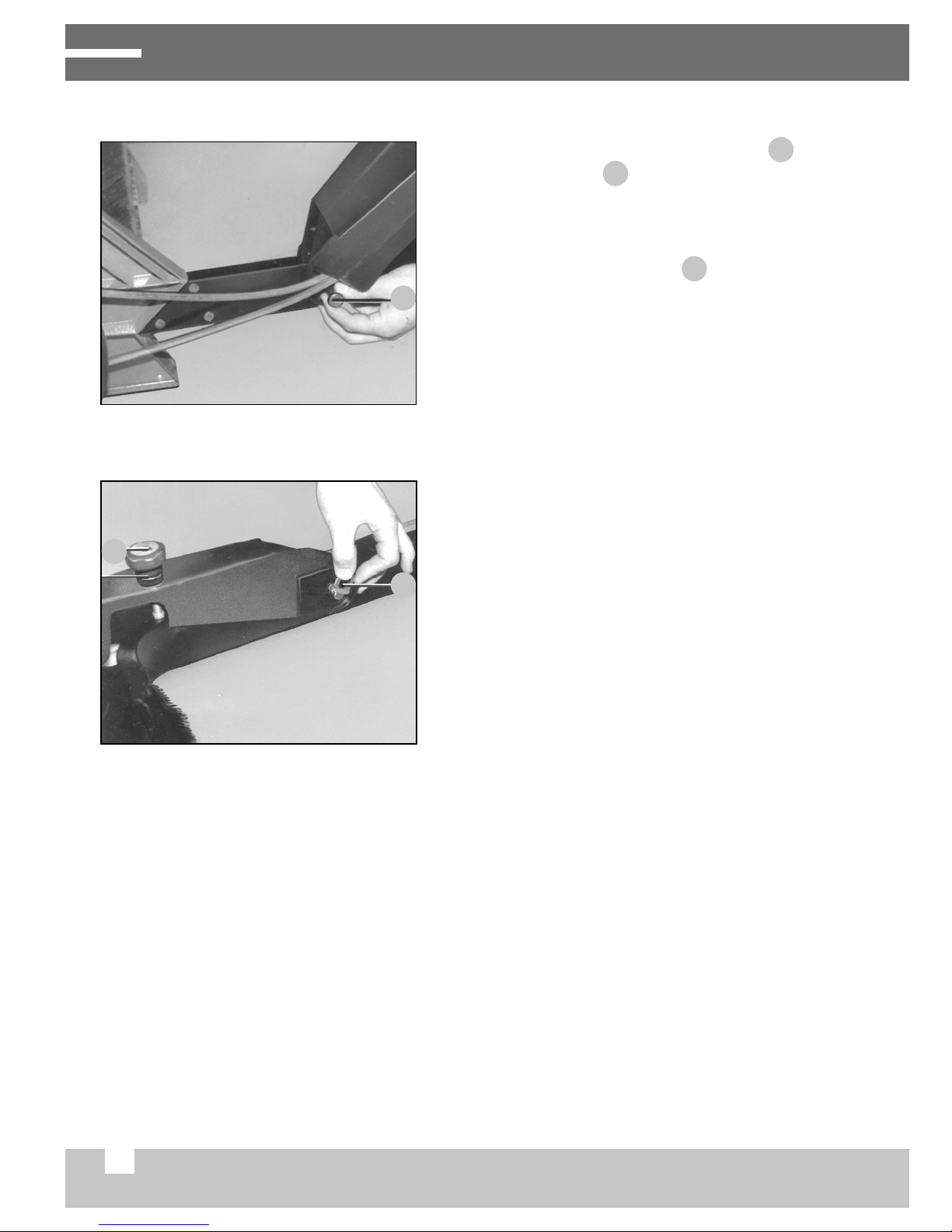
Putting into operation - Assembly
3. Attach size broom arm with plug
and safety pin . Introduce plug from
outside. Slue side broom down and
adjust broom height, or better said,
broom pressure with knurled-head
bolt loosen knurled nut . Side broom
should not be seated on the floor with
more than 2/3 of its circumference.
Secure with knurled checknut;
4. Check belt tension, adjust tension as
required (see chapter “Side broom”).
Seitenbesenanbau
Seitenbesenarm und Seitenbesen
aus der Verpackung entnehmen.
Seitenbesen auf die Besenwelle auf-
stecken und mit Halteschraube be-
festigen. Schlüsselweite: 10 mm.
(Halteschraube nur leicht anziehen,
so daß die Besennabe nicht ge-
quetscht wird.
Keilriemen über das rechte Rad in
die Nut der Riemenscheibe so
einlegen, daß der Seitenbesen bei
Vorwärtsfahrt gegen den Uhrzeiger-
sinn dreht (von oben gesehen).
Seitenbesenarm mit Bolzen (C/1)
und Halteklammer (D/3) befestigen
(Bolzen von außen nach innen ein-
stecken)
Seitenbesen herunterschwenken
und nach Lösen der Rändelmutter
(D/2) mit Handrad (D/1) die richtige
Besenauflage einstellen. Der
Seitenbesen darf nur mit ca. 2/3
seines vorderen Umfanges den
Boden berühren. Rändelmutter
(Kontermutter) wieder anziehen.
Inbetriebnahme
B
1
Seitenbesenanbau
Seitenbesenarm und Seitenbesen
aus der Verpackung entnehmen.
Seitenbesen auf die Besenwelle auf-
stecken und mit Halteschraube be-
festigen. Schlüsselweite: 10 mm.
(Halteschraube nur leicht anziehen,
so daß die Besennabe nicht ge-
quetscht wird.
Keilriemen über das rechte Rad in
die Nut der Riemenscheibe so
einlegen, daß der Seitenbesen bei
Vorwärtsfahrt gegen den Uhrzeiger-
sinn dreht (von oben gesehen).
Seitenbesenarm mit Bolzen (C/1)
und Halteklammer (D/3) befestigen
(Bolzen von außen nach innen ein-
stecken)
Seitenbesen herunterschwenken
und nach Lösen der Rändelmutter
(D/2) mit Handrad (D/1) die richtige
Besenauflage einstellen. Der
Seitenbesen darf nur mit ca. 2/3
seines vorderen Umfanges den
Boden berühren. Rändelmutter
(Kontermutter) wieder anziehen.
Keilriemenspannung kontrollieren,
ggf. spannen (siehe Absatz “Seiten-
besen” auf Seite 10)
Inbetriebnahme
B
C
1
3
2
3
4
4
2
3
Page 9

25
Operation
All controls are identified by easy-to-understand symbols which will help you to get
familiar with the machine.
The Kränzle 1+1 uses two brooms. The
dish-type side broom feeds the matter
swept to the main broom. The main
broom is rotating against the direction
of travel of the machine and throws the
dirt into the dirt hopper located at the
forward end. Both brooms are driven by
the machine wheels. A jackwheel will
guarantee uniform ground clearance and perfect sweeping.
The broom housing uses rubber seals all around to seal it against the floor
surface. At the forward end, the broom housing is closed by the dirt hopper,
at the rear end a large rubber lip is assembled.
If any part of the floor shall be omitted (smeared floor or transport), just lift both
brooms from the floor by depressing the handlebar. Steps and stairs are easily
overcome by the Kränzle 1+1.
The large wheels extend beyond the rear end of the machine. This means that
all usual obstacles are overcome by pulling the machine “uphill” or pushing it
“downhill”. The handlebar is folding to ease transportation or storage of the
Kränzle 1+1. For folding, loosen both wingbolts a few turns, expand the
handlebar structure and fold forward.
Inbetriebnahme
Bedienung
GB
Page 10

26
Operation
Inbetriebnahme
Einstellungsempfehlung
(gilt für neuwertige Kehrwalze)
Grundeinstellung: Skalenzahl 1,5
Skalen-
zahl
Kehrgut
1 leichter, trockener
Schmutz
glatt
2 schwerer Schmutz
oder große
Schmutzmenge,
feuchter oder
haftender Schmutz
rauh
oder
uneben
1,5 Grundeinstellung
Boden
4
1 Handwheel for sweeping roller
adjustment
2 Hopper handle
3 Stand legs of dirt hopper
4 Butterfly nuts for fixing of handlebar
5 Handwheel with knurled nut for side
brush adjustment
Sweeper Roller Adjustment
for recondioned sweeper rollers:
Scale code Litter Ground
1 Light-wight, dry litter Unruled
1,5 Basic adjustment Basic adjustment
2
Heavy dirt, or big dirt quantities;
humid or sticky dirt
Rough or uneven
Note:
Handwheel for sweeping roller adjustment is used for adjustment of the sweeping
roller ground pressure. The sweeping roller ground pressure should be adjusted
as recommended by us, or be adapted to local conditions, until good sweeping
performance will be achieved. Adjustment is indicated by the scale close to the
track wheel. Sweeping roller ground pressure, if adjusted to too high a value,
requires higher physical force to push the machine, and increases the wear of
brooms. Best sweeping performance will be achieved at 2.5 m.p.h. = 4 km.p.h.,
i.e. normal pedestrian´s speed.
1
2
3
4
5
3
Page 11

27
Operation
Handwheel to adjust side broom
The broom may touch the floor with the
forward 2/3 of its circumference only so
that it can feed the rubbish to the forward
end of the main broom and not sweep
it around only. The present working level
ofthe side broom is kept constant as
soon as the knurled nut (checknut)
is tightened in position. Too much surface
contact means increased power input and
unnecessary bristle wear.
Emptying the dirt hopper
To lift the dirt hopper, just use the handle
provided.
Insert the dirt hopper
Locate the hopper on the forward
frame as shown, and slue down.
Note: Do not place the dirt hopper
flat on ground to avoid damage to
the rubber lip. Use the four feet for
storing the detached hopper.
Keilriemen für
Seitenbesen spannen
Das Spannen des Keilriemens ist wie
folgt vorzunehmen:
Seitenbesen hochschwenken
Schrauben (B/2) lösen, ca 5 mm
herausdrehen
Rollenhalter (B/1) aus der Ausspa-
Seitenbesenarm hochschwenken
Halteschraube unterhalb des
Seitenbesens herausschrauben
(Schlüsselweite: 10 mm)
Seitenbesen abziehen
Neuen Seitenbesen aufstecken und
mit Halteschraube befestigen.
Halteschraube nur leicht anziehen,
so daß die Besennabe nicht
gequetscht wird.
Hinweis: Seitenbesenauflage mit
dem Handrad (A/1) so einstellen,
daß ca 2/3 des vorderen Besen-
umfanges den Boden berühren.
Zuviel Bodenauflage bedeutet er-
höhten Kraftbedarf und unnötigen
Borstenverschleiß.
Inbetriebnahme
1
Entleeren des
Schmutzbehälters
Handrad für
Seitenbeseneinstellung
Es dient zum Einstellen des Seiten-
besens. Der Seitenbesen darf nur
mit dem vorderen Zweidrittel seines
Umfanges den Boden berühren,
damit er das Kehrgut nur vor die
Kehrwalze wirft und es nicht mit
seinem rückwärtigen Teil wieder
zurückbefördert. Die eingestellte
Arbeitshöhe des Seitenbesens wird
durch das Festziehen der Rändel-
mutter (Kontermutter) eingehalten.
4
Inbetriebnahme
Entleeren des
Schmutzbehälters
Einsetzen des
Schmutzbehälters
Handrad für
Seitenbeseneinstellung
Es dient zum Einstellen des Seiten-
besens. Der Seitenbesen darf nur
mit dem vorderen Zweidrittel seines
Umfanges den Boden berühren,
damit er das Kehrgut nur vor die
Kehrwalze wirft und es nicht mit
seinem rückwärtigen Teil wieder
zurückbefördert. Die eingestellte
Arbeitshöhe des Seitenbesens wird
durch das Festziehen der Rändel-
mutter (Kontermutter) eingehalten.
Zum Entleeren ist der Schmutzbe-
hälter an seinem Griff nach oben
herauszuheben.
Behälter wie abgebildet auf den
Frontrahmen stellen und herunter-
schwenken.
Hinweis: Schmutzbehälter nicht
flach auf den Boden legen, die
Gummileiste kann beschädigt, bzw.
verformt werden. Zum Abstellen
des Behälters außerhalb des
Gerätes dienen die vier Füße an
der Frontseite.
4
Inbetriebnahme
GB
Page 12

28
Operation
Replacement of main broom
1. Slue side broom up.
2. Tilt machine back to rest on the
handlebar.
3. Remove three ea. Phillips screws,
turn broom roller 180°, remove Phillips
screws from second half.
4.
Pull the drive pin out of the broom shaft.
To install, reverse above procedure.
Die Kehrwalze hat 10 Borstenreihen
mit abwechselnd harten und weichen
Borsten. Sie besteht aus zwei Besen-
hälften.
Kehrwalzenbreite: 480 mm
Durchmesser: 250 mm
Durchmesser bei
Verschleißgrenze: 180 mm
Kehrwalze auswechseln
Inbetriebnahme
Die Kehrwalze hat 10 Borstenreihen
mit abwechselnd harten und weichen
Borsten. Sie besteht aus zwei Besen-
hälften.
Kehrwalzenbreite: 480 mm
Durchmesser: 250 mm
Durchmesser bei
Verschleißgrenze: 180 mm
Kehrwalze auswechseln
Das Auswechseln der Kehrwalze ist
wie folgt vorzunehmen:
Seitenbesen hochschwenken
Gerät nach hinten auf den Holm
kippen.
Inbetriebnahme
Die Kehrwalze hat 10 Borstenreihen
mit abwechselnd harten und weichen
Borsten. Sie besteht aus zwei Besen-
hälften.
Kehrwalzenbreite: 480 mm
Durchmesser: 250 mm
Durchmesser bei
Verschleißgrenze: 180 mm
Kehrwalze auswechseln
Das Auswechseln der Kehrwalze ist
wie folgt vorzunehmen:
Kreuzschlitzschrauben (3 Stück) an
der Kehrwalze herausschrauben,
Kehrwalze um 180° drehen und die
Kreuzschlitzschrauben aus der
zweiten Besenhälfte heraus-
schrauben. Mitnehmerstift aus der
Besenwelle herausziehen.
Der Anbau erfolgt in umgekehrter
Reihenfolge.
Seitenbesen hochschwenken
Gerät nach hinten auf den Holm
kippen.
Inbetriebnahme
Page 13

29
Side broom
Adjust tension of side broom Vee belt
1. Slue-up side broom.
2. Loosen bolts , should come out approx. 5 mm.
3. Lift roller holder from slot in plastic rib.
4. Slue roller holder out, introduce into next slot, slue back and tighten;
5. Slue down side broom, check tension, readjust as required.
Note: Adjust Vee belt tension just as far as required to ensure power
transmission. Do not adjust too high a tension of the Vee belt to avoid
excessive load and wear to the side broom, and to preclude poor sweeping
performance.
Replacement of side broom
1. Slue-up side broom arm.
2. Remove clamp screw underneath side broom (spanner size 10 mm).
3. Pull out side broom.
4. Plug-on new side broom and secure. Do not overtorque clamp screw to
avoid squeezing the bristles hub.
Keilriemen für
Seitenbesen spannen
Das Spannen des Keilriemens ist wie
folgt vorzunehmen:
Seitenbesen hochschwenken
Schrauben (B/2) lösen, ca 5 mm
herausdrehen
Rollenhalter (B/1) aus der Ausspa-
rung in der Kunststoffrippe heraus-
heben
Rollenhalter (B/1) nach außen
schwenken, in die nächste Rast-
stellung legen, zurückschwenken
und wieder festschrauben.
Seitenbesen herunterschwenken
und Spannung kontrollieren, ggf.
Einstellung korrigieren.
Hinweis: Keilriemen nur so weit
spannen, daß eine Kraftüber-
tragung gewährleistet ist. Ein
übermäßig gespannter Keilriemen
kann die Kehrwirkung des
Seitenbesens beeinträchtigen,
Seitenbesenarm hochschwenken
Halteschraube unterhalb des
Seitenbesens herausschrauben
(Schlüsselweite: 10 mm)
Seitenbesen abziehen
Neuen Seitenbesen aufstecken und
mit Halteschraube befestigen.
Halteschraube nur leicht anziehen,
so daß die Besennabe nicht
gequetscht wird.
Hinweis: Seitenbesenauflage mit
dem Handrad (A/1) so einstellen,
daß ca 2/3 des vorderen Besen-
umfanges den Boden berühren.
Zuviel Bodenauflage bedeutet er-
höhten Kraftbedarf und unnötigen
Borstenverschleiß.
Inbetriebnahme
1
2
A
1
2
1 Screws to tighten V-belt tension
2 roller holder
The side broom is driven by a Vee belt
from the RH wheel. Slueing down the
side broom will tension the belt, and
driving conditions thus will be
established.
GB
1
2
Page 14

30
Side broom
Replacement of side broom Vee belt
1. Remove side broom.
2.
Remove washers, deflector plate and
spacers from broom shaft.
3. Remove circlip, pull washers and pulley
with Vee belt o shaft (key should not
drop out from the shaft).
4.
Fit new Vee belt on pulley and reassemble
(reverse the above procedure).
Note: After having assembled the pulley,
check for key in place (refer to sketch
right above).
5. Check:
Move Vee belt to the right, shaft will
have to follow, move Vee belt to the
left, shaft will have to stand still
(view into side broom arm).
Keilriemen für
Seitenbesen auswechseln
Der Aus- bzw. Einbau des Keilriemens
ist wie folgt vorzunehmen:
Seitenbesen abbauen
Unterleg-Scheiben und Abweis-
teller, sowie weitere Unterleg-
scheiben von der Besenwelle ab-
nehmen (Abb. A.)
Sicherungsring abnehmen, Unter-
legscheiben und Riemenscheibe
mit Keilriemen von der Welle ab-
ziehen (darauf achten, daß der
Mitnehmerkeil nicht aus der Welle
Inbetriebnahme
Keilriemen für
Seitenbesen auswechseln
Der Aus- bzw. Einbau des Keilriemens
ist wie folgt vorzunehmen:
Kontrolle:
Keilriemen rechts herumdrehen, die
Welle muß jetzt mitdrehen, Keilriemen
links herumdrehen, die Welle muß
Seitenbesen abbauen
Unterleg-Scheiben und Abweis-
teller, sowie weitere Unterleg-
scheiben von der Besenwelle ab-
nehmen (Abb. A.)
Sicherungsring abnehmen, Unter-
legscheiben und Riemenscheibe
mit Keilriemen von der Welle ab-
ziehen (darauf achten, daß der
Mitnehmerkeil nicht aus der Welle
herausfällt)
Neuen Keilriemen auf die Riemen-
scheibe auflegen und Teile in um-
gekehrter Reihenfolge wieder
montieren.
Hinweis: Nach dem Aufsetzen der
Riemenscheibe auf die Welle,
kontrollieren, ob der Keil - falls
herausgefallen - richtig eingesteckt
worden ist (siehe rechts oben).
Inbetriebnahme
A
Sealing lips:
The rubber sealing lips will avoid dust to be expelled by the broom.
Damaged or worn-out lips will have to be replaced.
Page 15

31
Laufräder einfetten
Zum Reinigen und Einfetten der
Radachse und des Ritzels sind die
Laufräder wie folgt abzubauen:
Radkappen abnehmen.
Zwei Schraubendreher in die mit
Pfeilen gekennzeichneten Schlitze
stecken und Radkappe gleich-
mäßig abhebeln (Abb. A)
Sicherungsring auf der Radachse
entfernen und Laufrad abziehen
(Abb. C)
Inbetriebnahme
Laufräder einfetten
Zum Reinigen und Einfetten der
Radachse und des Ritzels sind die
Laufräder wie folgt abzubauen:
Radkappen abnehmen.
Zwei Schraubendreher in die mit
Pfeilen gekennzeichneten Schlitze
stecken und Radkappe gleich-
mäßig abhebeln (Abb. A)
Sicherungsring auf der Radachse
entfernen und Laufrad abziehen
(Abb. C)
Radachse und Ritzel einfetten (alle
Ritzelkammern füllen)
Laufrad wieder anbauen.
Radkappe aufsetzen gem. Abb. B,
dabei die richtige Position der
Fixierungspunkte (Pfeile) beachten.
Inbetriebnahme
A
B
Grease track wheels
For cleaning and greasing the axle and
pinion, remove track wheels as follows:
1. Remove hub caps. Insert two
screwdrivers into the slots marked by
arrows, and remove the hub cap using
the screwdriver as a lever, applying
force in a uniform manner
2. Then remove the circlip from the wheel
axle and remove the trackwheel.
3. Grease axle and pinion
(fill all pinion boxes).
4. Re-assemble track wheel. Attach hub
cap as shown in, check for index marks
in place (arrows).
Maintenance
GB
Page 16

32
Maintenance
Maintenance intervals
After each use
- Empty and clean dirt hopper.
- Clean the machine.
- Inspect broom bars and sealing lips.
Every 6 months
- Grease axles of track wheels and pinions.
- Check drive belt tensions, re-adjust as required.
Compliance with the maintenance work recommended by Kränzle will make
sure that your machine is ready to operate at any time.
If you are not in a postion to carry out the specified operations yourself, please
contact the nearest Kränzle service partner at www.kraenzle.com under the
heading „Dealers“.
Please have your machine number available for all repairs or parts orders.
It is printed on the data plate. The data plate is located at the left bottom
end of the frame.
Page 17

33
Warranty
GB
Warranty
Our warranty obligation is understood to exclusively cover material and
manufacturing defects; wear is not covered by warranty.
The machine is to be operated in conformity with this Operating manual.
The operating manual is deemed to be part of the warranty provisions.
This warranty shall only apply on condition of proper use of original-Kränzle
component parts and original-Kränzle replacement parts.
With regard to legal warranty claims, the limitation periods of the respective
countries shall apply.
In the event of any warranty claims, please have your accessories and purchase
voucher ready before contacting your local dealer or the nearest authorized
customer service point, which you can also find in the internet under
www.kraenzle.com .
In case of improper operation and non-performed maintenance of the cleaning
machine, subject warranty becomes null and void.
Belts, brushes, gearwheels are wear parts and are not covered by the Warranty
obligation.
Page 18

50
Ersatzteilliste Müllbehälter, Rahmen, Lenkholm
Spare parts list dirt hopper, frame, steering bar
Ersatzteilliste
Page 19

51
1+1 Handkehrmaschine
1+1 hand powered sweeper
Pos. Bezeichnung Stück Art.-Nr.
1 Rahmen 1 51.001
2 Schmutzbehälter 1 51.002
3 Holm 1 51.003
4 Gribügel 1 51.004
5 Sechskantmutter 2 51.005
6 Scheibe 2 51.006
7 Buchse 2 51.007
8 Flachrundschraube 2 51.008
9 Kehrleiste 1 51.009
10 Blechschraube 5 51.010
11 Schraube 6 51.011
12 Gummidichtung 1 51.012
13 Zylinderschraube 1 51.013
14 Lenkrolle 1 51.014
15 O-Ring 2 51.015
Page 20

52
Ersatzteilliste Besenwelle, Gehäuse, Räder
Spare parts list broom shaft, housing, wheels
Ersatzteilliste
Page 21

53
1+1 Handkehrmaschine
1+1 hand powered sweeper
Pos. Bezeichnung Stück Art.-Nr.
1 Radkappe 2 51.016
2 Rad kpl. (Außenzahnfelge) 1 51.017
3 Dichtungskörper 1 51.018
4 Flachrundkopfschraube 8 51.019
5 Kehrgehäuse 1 51.020
6 Flügelmutter 2 51.021
7 Handrad 1 51.022
8 Scheibe 5 51.023
9 Sechskantmutter 3 51.024
10 Dichtprofil 1 51.025
11 Gewindestange 1 51.026
12 Scheibe 2 51.027
13 Sechskantmutter 2 51.028
14 Bolzen 1 51.029
15 Hebelwelle 1 51.030
16 Sechskantschraube 6 51.031
17 Radachse 2 51.032
18 Sechskantmutter 6 51.033
19 Besenschwinge 2 51.034
20 Paßscheibe 10 51.035
21 Buchse 4 51.036
22 Sicherungsring 5 51.037
23 Freilaufritzel 1 51.038
24 Kugellager 2 51.039
25 Linsenkopfschraube 6 51.040
26 Keil 1 51.041
27 Besenwelle 1 51.042
28 Kehrwalze m. Pos. 21 + 27 1 51.043
29 Zylinderstift 1 51.044
30 Tesamoll 1 51.045
31 Sechskantmutter 3 51.046
32 Flachrundschraube 2 51.047
33 Stützscheibe 1 51.048
Page 22

54
Ersatzteilliste Seitenbesen
Spare parts list side boom
Ersatzteilliste
23
22
21
20
19
18
15
17
16
15
22
15
14
13
12
Spare part list
Spare part list
Page 23

55
1+1 Handkehrmaschine
1+1 hand powered sweeper
Pos. Bezeichnung Stück Art.-Nr.
1 Seitenbesenarm 1 51.049
2 Rändelmutter 1 51.050
3 Handrad 1 51.051
4 Sicherungsblech 1 51.052
5 Bolzen 1 51.053
6 Sechskantmutter 1 51.054
7 Schutzhülse 1 51.055
8 Riemenrolle, kpl. 1 51.056
9 Scheibe 3 51.057
10 Schraube 3 51.058
11 Keilriemen 1 51.059
12 Seitenbesen 1 51.060
13 Passscheibe 1 51.061
14 Abweisteller 1 51.062
15 Passscheibe 3 51.063
16 Keilriemenscheibe 1 51.064
17 Sechskantschraube 1 51.065
18 Sechskantmutter 1 51.066
19 Keil 1 51.067
20 Welle 1 51.068
21 Kugellager 1 51.069
22 Sicherungsring 2 51.070
23 Kugellager 1 51.071
24 Seitenbesen, kpl. 1 51.072
Page 24

www.kraenzle.com
Made
in
Germany
Stand 15.06.2015, Art.-Nr. 30.814 0
Technische Änderungen und Irrtümer vorbehalten.
Ingrid Kränzle GmbH
Elpke 97
33605 Bielefeld (Germany)
Telefon: +49 (0) 521 / 9 26 26-0
Telefax: +49 (0) 521 / 9 26 26-40
info@kraenzle.com
 Loading...