

Page 1

Kramer Electronics, Ltd.
USER MANUAL
Model:
VP-2x2
2x2 XGA/Audio Matrix Switcher
Page 2

Contents
Contents
1
Introduction 1
2
Getting Started 1
2.1 Quick Start 1
3
Overview 3
4
Your VP-2x2 2x2 XGA/Audio Matrix Switcher 4
5
Connecting the VP-2x2 2x2 XGA/Audio Matrix Switcher 5
5.1 Connecting the VP-2x2 2x2 XGA/Audio Matrix Switcher Rear Panel 5
5.2 Connecting the Balanced/Unbalanced Stereo Audio Input/Output 7
5.3 Connecting a PC 8
6
Operating Your XGA/Audio Matrix Switcher 9
6.1 Choosing the Audio-Follow-Video or Breakaway Option 9
6.1.1 Setting the Audio-Follow-Video Option 9
6.1.2 Setting the Breakaway Option 9
6.2 Locking the Front Panel 10
7
Technical Specifications 10
8
Kramer Protocol 2000 11
9
Table of Hex Codes for Serial Communication 13
Figures
Figure 1: VP-2x2 2x2 XGA/Audio Matrix Switcher 4
Figure 2: Connecting the VP-2x2 2x2 XGA/Audio Matrix Switcher 6
Figure 3: Connecting the Balanced Stereo Audio Input/Output 7
Figure 4: Connecting the Unbalanced Stereo Audio Input 7
Figure 5: Connecting an Unbalanced Output 7
Figure 6: Connecting the PC 8
Tables
Table 1: VP-2x2 2x2 XGA/Audio Matrix Switcher Features 4
Table 2: Technical Specifications of the VP-2x2 2x2 XGA/Audio Matrix Switcher 10
Table 3: Protocol Definitions 11
Table 4: Instruction Codes for Protocol 2000 12
Table 5: Hex Codes 13
i
Page 3

Introduction
1 Introduction
Welcome to Kramer Electronics! Since 1981, Kramer Electronics has been
providing a world of unique, creative, and affordable solutions to the vast
range of problems that confront the video, audio, presentation, and
broadcasting professional on a daily basis. In recent years, we have
redesigned and upgraded most of our line, making the best even better! Our
500-plus different models now appear in eight groups1 that are clearly defined
by function.
Congratulations on purchasing your Kramer VP-2x2 2x2 XGA/Audio Matrix
Switcher. This product is ideal for the following typical applications:
Any professional display system requiring a true 2x2 matrix operation
Multimedia and presentation sources and acceptors selection
Remote monitoring of computer activity in schools and businesses
The package includes the following items:
VP-2x2 2x2 XGA/Audio Matrix Switcher
Power adapter (12V DC Input)
Windows®-based Kramer control software2
Null-modem adapter
This user manual3
2 Getting Started
We recommend that you:
Unpack the equipment carefully and save the original box and packaging
materials for possible future shipment
Review the contents of this user manual
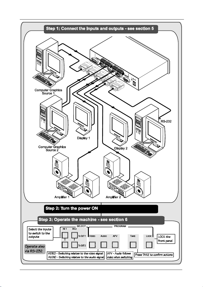
2.1 Quick Start
This quick start chart summarizes the basic setup and operation steps of the
VP-2x2.
1 GROUP 1: Distribution Amplifiers; GROUP 2: Video and Audio Switchers, Matrix Switchers and Controllers; GROUP 3:
Video, Audio, VGA/XGA Processors; GROUP 4: Interfaces and Sync Processors; GROUP 5: Twisted Pair Interfaces;
GROUP 6: Accessories and Rack Adapters; GROUP 7: Scan Converters and Scalers; and GROUP 8: Cables and Connectors
2 Downloadable from our Web site at http://www.kramerelectronics.com
3 Download up-to-date Kramer user manuals from our Web site at http://www.kramerelectronics.com
1
Page 4
Getting Started
2
KRAMER: SIMPLE CREATIVE TECHNOLOGY
Page 5
Overview
3 Overview
The VP-2x2 is a high performance matrix switcher for VGA/SVGA/XGA/UXGA
signals and balanced stereo audio signals. The user can simultaneously route
an input to one or both outputs
1
.
In addition, the VP-2x2 includes:
Video bandwidth that exceeds 400
MHz, ensuring transparent
performance in all applications
Audio-follow-video switching and audio breakaway (when audio and
video are switched separately)
A TAKE button that allows the user to pre-select a setting and then
activate it
A LOCK button to prevent tampering via the front panel
Control via the front panel buttons, or remotely by RS-232 serial
commands transmitted by a touch screen system, PC, or other serial
controller
To achieve the best performance:
Connect only good quality connection cables, thus avoiding interference,
deterioration in signal quality due to poor matching, and elevated noise
levels (often associated with low quality cables)
Avoid interference from neighboring electrical appliances that may
adversely influence signal quality and position your Kramer VP-2x2 in a
location free from moisture and away from excessive sunlight and dust
Caution – No operator-serviceable parts inside unit.
Warning – Use only the Kramer Electronics input power
wall adapter that is provided with this unit
Warning – Disconnect power and unplug unit from wall
before installing or removing device or servicing unit.
2
.
1 Input 1 (or 2) to outputs 1 and 2 simultaneously, or input 1 (or 2) to output 1 and input 2 (or 1) to output 2
2 For example: model number AD2512C, part number 2535-000251
3
Page 6
Your VP-2x2 2x2 XGA/Audio Matrix Switcher
4 Your VP-2x2 2x2 XGA/Audio Matrix Switcher
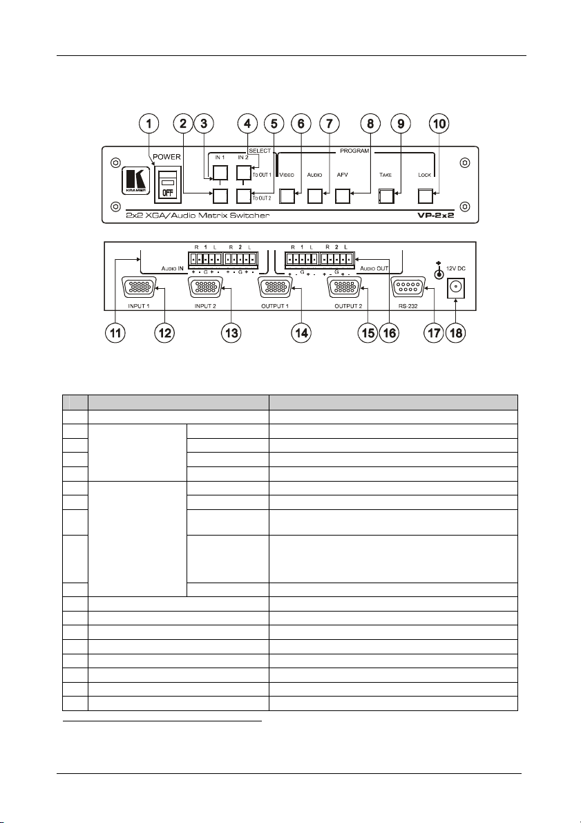
Figure 1 and Table 1 define the front and rear panels of the VP-2x2:
Figure 1: VP-2x2 2x2 XGA/Audio Matrix Switcher
Table 1: VP-2x2 2x2 XGA/Audio Matrix Switcher Features
# Feature Function
1 POWER Switch Illuminated switch for turning the unit ON or OFF
2 IN 1 To OUT 2 Switches input 1 to output 2
3 IN 1 To OUT 1 Switches input 1 to output 1
SELECT Buttons1
4 IN 2 To OUT 1 Switches input 2 to output 1
5
6 VIDEO When illuminated, actions relate to video
7 AUDIO When illuminated, actions relate to audio
8 AFV When illuminated, audio channels follow the video
SELECT Buttons1
9 TAKE Pressing TAKE toggles the mode between the Confirm
10
11 AUDIO IN Terminal Block Connectors Connects to the 2 balanced audio inputs
12 INPUT 1 HD15F Connector Connects to the video source 1
13 INPUT 2 HD15F Connector Connects to the video source 2
14 OUTPUT 1 HD15F Connector Connects to the video acceptor 1
15 OUTPUT 2 HD15F Connector Connects to the video acceptor 2
16 AUDIO OUT Terminal Block Connectors Connects to the 2 balanced audio outputs
17 RS-232 9-pin D-sub Connector Connects to PC or Remote Controller
18 12V DC +12V DC connector for powering the unit
1 Press to select. When selected, the button illuminates
2 When in the Confirm mode, the TAKE button illuminates
IN 2 To OUT 2 Switches input 2 to output 2
channels
mode2 and the At Once mode (user confirmation per
action is unnecessary). In Confirm mode, TAKE
implements the pending action
LOCK Disengages/engages the front panel buttons
4
KRAMER: SIMPLE CREATIVE TECHNOLOGY
Page 7

Connecting the VP-2x2 2x2 XGA/Audio Matrix Switcher
5 Connecting the VP-2x2 2x2 XGA/Audio Matrix Switcher
This section describes how to connect:
The VP-2x2 rear panel (see section 5.1)
A balanced stereo audio input/output (see section 5.2)
The VP-2x2 to a controlling device via RS-232 (see section 5.2)
5.1 Connecting the VP-2x2 2x2 XGA/Audio Matrix Switcher Rear Panel
To connect1 the VP-2x2, as illustrated in the example in Figure 2, do the
following2:
1. Connect the VGA/UXGA computer graphics sources to the INPUT 15pin HD computer graphics video connectors.
2. Connect the balanced3 stereo audio sources to the AUDIO IN balanced
stereo audio 5-pin terminal block connectors.
3. Connect the OUTPUT 15-pin HD computer graphics video connectors to
the VGA/UXGA video acceptors (for example, displays).
4. Connect the AUDIO OUT terminal block connectors to the balanced3
stereo audio acceptors (for example, amplifiers with speakers).
5. Connect a PC and/or controller (if required) to the RS-232 port (see
section 5.2).
6. Connect the 12V DC power adapter to the power socket and connect the
adapter to the mains electricity (not shown in Figure 2).
1 You do not have to connect both inputs or both outputs
2 Switch OFF the power on each device before connecting it to your VP-2x2. After connecting your VP-2x2, switch on its
power and then switch on the power on each device
3 See section 5.2
5
Page 8

Connecting the VP-2x2 2x2 XGA/Audio Matrix Switcher
Figure 2: Connecting the VP-2x2 2x2 XGA/Audio Matrix Switcher
6
KRAMER: SIMPLE CREATIVE TECHNOLOGY
Page 9

Connecting the VP-2x2 2x2 XGA/Audio Matrix Switcher
5.2 Connecting the Balanced/Unbalanced Stereo Audio Input/Output
This section illustrates how to wire:
A balanced input/output connection, see Figure 3
An unbalanced audio input, see Figure 4
An unbalanced audio output, see Figure 5
Figure 3: Connecting the Balanced Stereo Audio Input/Output
Figure 4: Connecting the Unbalanced Stereo Audio Input
Figure 5: Connecting an Unbalanced Output
7
Page 10

Connecting the VP-2x2 2x2 XGA/Audio Matrix Switcher
9-pin D-sub
9-pin D-sub
(To Switcher)
PIN 5 Connected to PIN 5 (Ground)
5.3 Connecting a PC
You can connect a PC (or other controller) to the VP-2x2 via the RS-232 port
for remote control, and for upgrading the firmware.
To connect a PC to a VP-2x2 unit, using the Null-modem adapter provided
with the machine (recommended):
Connect the RS-232 9-pin D-sub rear panel port on the VP-2x2 unit to the
Null-modem adapter and connect the Null-modem adapter with a 9-wire
flat cable to the RS-232 9-pin D-sub port on your PC
To connect a PC to a VP-2x2 unit, without using a Null-modem adapter:
Connect the RS-232 9-pin D-sub port on your PC to the RS-232 9-pin
D-sub rear panel port on the VP-2x2 unit, forming a cross-connection1, as
Figure 6 illustrates
PIN 3 Connected to PIN 2
PIN 2 Connected to PIN 3
(From PC)
If a shielded cable is used, connect the shield to PIN 5
Figure 6: Connecting the PC
1 Also known as a Null-modem connection
8
KRAMER: SIMPLE CREATIVE TECHNOLOGY
Page 11

Operating Your XGA/Audio Matrix Switcher
6 Operating Your XGA/Audio Matrix Switcher
Operate your VP-2x2 via:
The front panel buttons
RS-232 serial commands transmitted by a touch screen system, PC, or
other serial controller
6.1 Choosing the Audio-Follow-Video or Breakaway Option
You can switch balanced stereo audio signals in one of two ways, either:
Audio-follow-video (AFV), in which all operations relate to both the
video and the audio channels1; or
Breakaway, in which video and audio channels switch independently
6.1.1 Setting the Audio-Follow-Video Option
To set the Audio-follow-video (AFV) option press the AFV button:
If the AUDIO and VIDEO configurations are the same, then the AFV
button illuminates. The audio will follow the video
If the AUDIO differs from the VIDEO, then the AUDIO button will flash,
and require reconfiguring for AFV operation. Press the TAKE button to
confirm the modification (reconfiguring the audio according to the video)
6.1.2 Setting the Breakaway Option
To set the Breakaway option:
Press either the AUDIO (for audio control only) or the VIDEO (for video
control only) button:
If the AUDIO button illuminates, switching operations relate to audio
If the VIDEO button illuminates, switching operations relate to video
1 Audio and video connections are the same
9
Page 12

Technical Specifications
6.2 Locking the Front Panel
To prevent changing the settings accidentally or tampering with the unit via
the front panel buttons, lock1 your VP-2x2. Unlocking releases the protection
mechanism.
To lock the VP-2x2:
Press the LOCK button for more than two seconds, until the LOCK button
is illuminated
The front panel is locked. Pressing a button will have no effect other than
causing the LOCK button to blink2
To unlock the VP-2x2:
Press the illuminated LOCK button, for more than two seconds, until the
LOCK button is no longer illuminated and the front panel unlocks
7 Technical Specifications
Table 2 includes the technical specifications:
Table 2: Technical Specifications of the VP-2x2 2x2 XGA/Audio Matrix Switcher
INPUTS: 2 VGA/UXGA on HD15F connectors
OUTPUTS: 2 VGA/UXGA on HD15F connectors
MAX. OUTPUT LEVEL: Video: 1.7Vpp; Audio: 7.2Vpp
BANDWIDTH (-3dB): Video: 400MHz, Audio: 100kHz
DIFF. GAIN: 0.05%
DIFF. PHASE: 0.05 deg.
K-FACTOR: <0.05%
S/N RATIO: Video: 78.3dB; Audio: 95dB, unweighted
CROSSTALK: Video: -43dB; Audio: 77dB @ 1kHz
CONTROLS: Front panel touch switches, RS-232
COUPLING: DC
AUDIO THD + NOISE: <0.049%
AUDIO 2nd HARMONIC: <0.003%
POWER SOURCE: 12VDC, 150mA.
DIMENSIONS: 22cm x 18cm x 4.5cm (8.7” x 7” x 1.7”) W, D, H, (half 19”, 1U).
WEIGHT: 1.1kg (2.4lbs) approx.
ACCESSORIES: Power supply, Null modem adapter, Windows 95/98/2000/NT™ Kramer
OPTIONS: 19” rack adapters
2 balanced stereo audio on detachable terminal block connectors
2 balanced stereo audio on detachable terminal block connectors
control software
1 Even when the front panel is locked you can still operate via RS-232
2 Warning that you need to unlock to regain control via the front panel
10
KRAMER: SIMPLE CREATIVE TECHNOLOGY
Page 13

Kramer Protocol 2000
8 Kramer Protocol 20001
The VP-2x2 is compatible with Kramer’s Protocol 2000 (version 0.50)
(below). This RS-232/RS-485 communication protocol uses four bytes of
information as defined below. For RS-232, a null-modem connection between
the machine and controller is used. The default data rate is 9600 baud, with
no parity, 8 data bits and 1 stop bit.
Table 3: Protocol Definitions
MSB LSB
DESTI-
0 D N5 N4 N3 N2 N1 N0
7 6 5 4 3 2 1 0
1st byte
INPUT
1 I6 I5 I4 I3 I2 I1 I0
7 6 5 4 3 2 1 0
2nd byte
OUTPUT
1 O6 O5 O4 O3 O2 O1 O0
7 6 5 4 3 2 1 0
3rd byte
MACHINE NUMBER
1 OVR X M4 M3 M2 M1 M0
7 6 5 4 3 2 1 0
4th byte
1st BYTE: Bit 7 – Defined as 0.
D – “DESTINATION”: 0 - for sending information to the switchers (from the PC);
1 - for sending to the PC (from the switcher).
N5…N0 – “INSTRUCTION”
The function that is to be performed by the switcher(s) is defined by the INSTRUCTION (6 bits). Similarly, if a function is
performed via the machine’s keyboard, then these bits are set with the INSTRUCTION NO., which was performed. The
instruction codes are defined according to the table below (INSTRUCTION NO. is the value to be set for N5…N0).
2nd BYTE: Bit 7 – Defined as 1.
I6…I0 – “INPUT”.
When switching (ie. instruction codes 1 and 2), the INPUT (7 bits) is set as the input number which is to be switched.
Similarly, if switching is done via the machine’s front-panel, then these bits are set with the INPUT NUMBER which was
switched. For other operations, these bits are defined according to the table.
3rd BYTE: Bit 7 – Defined as 1.
O6…O0 – “OUTPUT”.
When switching (ie. instruction codes 1 and 2), the OUTPUT (7 bits) is set as the output number which is to be switched.
Similarly, if switching is done via the machine’s front-panel, then these bits are set with the OUTPUT NUMBER which was
switched. For other operations, these bits are defined according to the table.
4th BYTE: Bit 7 – Defined as 1.
Bit 5 – Don’t care.
OVR – Machine number override.
M4…M0 – MACHINE NUMBER.
Used to address machines in a system via their machine numbers. When several machines are controlled from a single serial
port, they are usually configured together with each machine having an individual machine number. If the OVR bit is set, then
all machine numbers will accept (implement) the command, and the addressed machine will reply.
NATION
INSTRUCTION
1 You can download our user-friendly “Software for Calculating Hex Codes for Protocol 2000” from the technical support
section on our Web site at: http://www.kramerelectronics.com
11
Page 14

Kramer Protocol 2000
For a single machine controlled via the serial port, always set M4…M0 = 1, and make sure that the machine itself is
configured as MACHINE NUMBER = 1.
Table 4: Instruction Codes for Protocol 2000
Note: All values in the table are decimal, unless otherwise stated.
INSTRUCTION DEFINITION FOR SPECIFIC INSTRUCTION
# DESCRIPTION INPUT OUTPUT
0 RESET VIDEO 0 0 1
1 SWITCH VIDEO Set equal to video input
2 SWITCH AUDIO Set equal to audio input
5 REQUEST STATUS OF A VIDEO
OUTPUT
6 REQUEST STATUS OF AN
AUDIO OUTPUT
8 BREAKAWAY SETTING 0
11 REQUEST BREAKAWAY
SETTING
12 REQUEST VIDEO / AUDIO TYPE
SETTING
30 LOCK FRONT PANEL 0 - Panel unlocked
31 REQUEST WHETHER PANEL IS
LOCKED
57 SET AUTO-SAVE I3 - no save
61 IDENTIFY MACHINE 1 - video machine name
62 DEFINE MACHINE 1 - number of inputs
NOTES on the above table:
NOTE 1 - When the master switcher is reset, (e.g. when it is turned on), the reset code is sent to the PC. If this code is sent to
the switchers, it will reset according to the present power-down settings.
NOTE 2 - These are bi-directional definitions. That is, if the switcher receives the code, it will perform the instruction; and if
the instruction is performed (due to a keystroke operation on the front panel), then these codes are sent. For example, if the
HEX code
01 82 81 81
was sent from the PC, then the switcher (machine 1) will switch input 2 to output 1. If the user switched input 1 to output 2
via the front panel keypad, then the switcher will send HEX codes:
41 81 82 81
to the PC.
When the PC sends one of the commands in this group to the switcher, then, if the instruction is valid, the switcher replies by
sending to the PC the same four bytes that it was sent (except for the first byte, where the DESTINATION bit is set high).
NOTE 4 - The reply to a "REQUEST" instruction is as follows: the same instruction and INPUT codes as were sent are
returned, and the OUTPUT is assigned the value of the requested parameter. The reply to instruction 11 is as per the
definitions in instruction 8. For example, if the present status of machine number 1 is breakaway setting, then the reply to the
HEX code
0B 80 80 81
would be HEX codes
4B 80 81 81
which is to be switched
(0 = disconnect)
which is to be switched
(0 = disconnect)
0 Equal to output number whose
0 Equal to output number whose
0, or set to 126 or 127 to
request if machine has this
function
0, or set to 126 or 127 to
request if machine has this
function
1 - Panel locked
0 0 16
I4 - auto-save
2 - audio machine name
3 - video software version
4 - audio software version
2 - number of outputs
3 - number of setups
Set equal to video output which is
to be switched
(0 = to all the outputs)
Set equal to audio output which is
to be switched
(0 = to all the outputs)
status is reqd
status is reqd
0 - audio-follow-video
1 - audio breakaway
0 - Request audio breakaway
setting
0 - for video
1 - for audio
2 - for VGA
0 2
0 12, 2
0 13
1 - for video
2 - for audio
3 - for SDI
4 - for remote panel
5 - for RS-422 controller
NOTE
2
2
4
4
2
4, 6
4, 6
14
12
KRAMER: SIMPLE CREATIVE TECHNOLOGY
Page 15

Table of Hex Codes for Serial Communication
NOTE 6 – If INPUT is set to 127 for these instructions, then, if the function is defined on this machine, it replies with
OUTPUT=1. If the function is not defined, then the machine replies with OUTPUT=0, or with an error (invalid instruction
code).
If the INPUT is set to 126 for these instructions, then, if possible, the machine will return the current setting of this function,
even for the case that the function is not defined.
NOTE 12 - Under normal conditions, the machine's present status is saved each time a change is made. The "power-down"
save (auto-save) may be disabled using this code. Note that whenever the machine is turned on, the auto-save function is set.
NOTE 13 - This is a request to identify the switcher/s in the system. If the OUTPUT is set as 0, and the INPUT is set as 1 or
2, the machine will send its name. The reply is the decimal value of the INPUT and OUTPUT. For example, for a VP-2x2, the
reply to the request to send the audio machine name would be (HEX codes):
7D 82 82 81 (i.e. 128dec+ 21dec for 2nd byte, and 128dec+ 2dec for 3rd byte).
If the request for identification is sent with the INPUT set as 3 or 4, the appropriate machine will send its software version
number. Again, the reply would be the decimal value of the INPUT and OUTPUT - the INPUT representing the number in
front of the decimal point, and the OUTPUT representing the number after it. For example, for version 3.5, the reply to the
request to send the version number would be (HEX codes):
7D 83 85 81 (i.e. 128dec+ 3dec for 2nd byte, 128dec+ 5dec for 3rd byte).
NOTE 14 - The number of inputs and outputs refers to the specific machine which is being addressed, not to the system.
9 Table of Hex Codes for Serial Communication
Table 5 lists the Hex values for switching on the VP-2x2.
Table 5: Hex Codes
OUT 1 OUT 2
OUT 1
OUT 2
2
2
2
2
13
Page 16

LIMI TED WARR ANTY
Kramer Electronics (hereafter ) warrants this product free from defects in material and workmanship under the
following terms.
HOW LONG IS TH E WARRANTY
Labor and parts are warranted for seven years from the date of the first customer purchase.
WHO IS PROTECT ED?
Only the first purchase customer may enforce this warranty.
WHAT IS CO VER ED AND WHAT IS NOT COVERE D
Except as below, this warranty covers all defects in material or workmansh ip in this product. The following are not covered
by the warranty:
1. Any product which is not distributed by Kramer, or which is not purchased from an authorized Kramer dealer. If you are
uncertain as to whether a dealer is authorized, please contact Kramer at one of the agents listed in the Web site
www.kramerelectronics.com.
2. Any product, on which the serial number has been defaced, modified or removed, or on which the WARRANTY VOID
TAMPERED sticker has been torn,
IF reattached, removed or otherwise interfered with.
3. Damage, deterioration or malfunction resulting from:
i) Accident, misuse, abuse, neglect, fire, water, lightning or other acts of nature
ii) Product modification, or failure to follow instructions supplied with the product
iii) Repair or attempted repair by anyone not authorized by Kramer
iv) Any shipment of the product (claims must be presented to the carrier)
v) Removal or installation of the product
vi) Any other cause, which does not relate to a product defect
vii) Cartons, equipment enclosures, cables or accessories used in conjunction with the product
WHAT WE WILL PAY FOR A ND WHAT WE WILL NOT PAY FOR
We will pay labor and material expenses for covered items. We will not pay for the following:
1. Removal or installations charges.
2. Costs of initial technical adjustments (set-up), including adjustment of user controls or programming. These costs are the
responsibility of the Kramer dealer from whom the product was purchased.
3. Shipping charges.
HOW YOU CA N GET WARRANT Y SERVIC E
1. To obtain service on you product, you must take or ship it prepaid to any authorized Kramer service center.
2. Whenever warranty service is required, the original dated invoice (or a copy) must be presented as proof of warranty
coverage, and should be included in any shipment of the product. Please also include in any mailing a contact name,
company, address, and a description of the problem(s).
3. For the name of the nearest Kramer authorized service center, consult your authorized dealer.
LIMI TATION OF IMP LIED WA RRANTIES
All implied warranties, including warranties of merchantability and fitness for a particular purpose, are limited in duration to
the length of this warranty.
EXCLUSIO N O F DAMAGES
The liability of Kramer for any effective products is limited to the repair or replacement of the product at our option. Kramer shall
not be liable for:
1. Damage to other property caused by defects in this product, damages based upon inconvenience, loss of use of the product, loss
of time, commercial loss; or:
2. Any other damages, whether incidental, consequential or otherwise. Some countries may not allow limitations on how long an
implied warranty lasts and/or do not allow the exclusion or limitation of incidental or consequential damages, so the above
limitations and exclusions may not apply to you.
This warranty gives you specific legal rights, and you may also have other rights, which vary from place to place.
All products returned to Kramer for service must have prior approval. This may be obtained from your dealer.
NOTE:
This equipment has been tested to determine compliance with the requirements of:
EN-50081: "Electromagnetic compatibility (EMC);
Residential, commercial and light industry"
EN-50082: "Electromagnetic compatibility (EMC) generic immunity standard.
CFR-47: FCC Rules and Regulations:
CAUTI ON!
generic emission standard.
Part 1:
Part 1: Residential, commercial and light industry environment".
Part 15: “Radio frequency devices
Subpart B Unintentional radiators”
Servicing the machines can only be done by an authorized Kramer technician. Any user who makes changes or
modifications to the unit without the expressed approval of the manufacturer will void user authority to operate the
equipment.
Use the supplied DC power supply to feed power to the machine.
Please use recommended interconnection cables to connect the machine to other components.
Kramer
14
KRAMER: SIMPLE CREATIVE TECHNOLOGY
Page 17

For the latest information on our products and a list of Kramer
distributors, visit our Web site: www.kramerelectronics.com,
where updates to this user manual may be found.
We welcome your questions, comments and feedback.
Safety Warning:
Disconnect the unit from the power supply before
opening/servicing.
Caution
Kramer Electronics, Ltd.
Web site: www.kramerelectronics.com
E-mail: info@kramerel.com
P/N: 2900-002059 REV 3
 Loading...