

Page 1

Kramer Electronics, Ltd.
USER MANUAL
Model:
VM-22HD
2 x 1:2 HD/SD-SDI DA
Page 2

Contents
Contents
1 Introduction 1
2 Getting Started 1
2.1 Quick Start 2
3 Overview 3
4 Your VM-22HD 2 x 1:2 HD/SD-SDI DA 4
5 Connecting the VM-22HD 2 x 1:2 HD/SD-SDI DA 5
5.1 Connecting the VM-22HD in the Single Link Mode 5
5.2 Connecting the VM-22HD in the Dual Link Mode 6
6 Technical Specifications 7
Figures
Figure 1: VM-22HD 2 x 1:2 HD/SD-SDI DA 4
Figure 2: Connecting the VM-22HD in Single Link Mode 5
Figure 3: Connecting the VM-22HD in Dual Link Mode 6
Tables
Table 1: VM-22HD 2 x 1:2 HD/SD-SDI DA Functions 4
Table 2: VM-22HD 2 x 1:2 HD/SD-SDI DA Technical Specifications 7
i
Page 3

Introduction
1 Introduction
Welcome to Kramer Electronics! Since 1981, Kramer Electronics has been
providing a world of unique, creative, and affordable solutions to the vast
range of problems that confront the video, audio, presentation, and
broadcasting professional on a daily basis. In recent years, we have
redesigned and upgraded most of our line, making the best even better! Our
1,000-plus different models now appear in 11 groups
defined by function.
Thank you for purchasing the Kramer DigiTOOLS
2 x 1:2 HD/SD-SDI DA, which is ideal for:
• SDI production studios for signal distribution
• Broadcast studios for on-air operation and SDI field production
• Using with SDI video sources such a professional digital camera
• Signal equalization after long cable runs
The package includes the following items:
• The VM-22HD 2 x 1:2 HD/SD-SDI DA
• Power supply (12V DC / 250mA)
• This user manual
2
1
that are clearly
®
VM-22HD
2 Getting Started
We recommend that you:
• Unpack the equipment carefully and save the original box and
packaging materials for possible future shipment
• Review the contents of this user manual
• Use Kramer high performance high-resolution cables
3
1 GROUP 1: Distribution Amplifiers; GROUP 2: Switchers and Matrix Switchers; GROUP 3: Control Systems;
GROUP 4: Format/Standards Converters; GROUP 5: Range Extenders and Repeaters; GROUP 6: Specialty AV Products;
GROUP 7: Scan Converters and Scalers; GROUP 8: Cables and Connectors; GROUP 9: Room Connectivity;
GROUP 10: Accessories and Rack Adapters; GROUP 11: Sierra Products
2 Download up-to-date Kramer user manuals from our Web site at http://www.kramerelectronics.com
3 The complete list of Kramer cables is on our Web site at http://www.kramerelectronics.com
1
Page 4
Getting Started
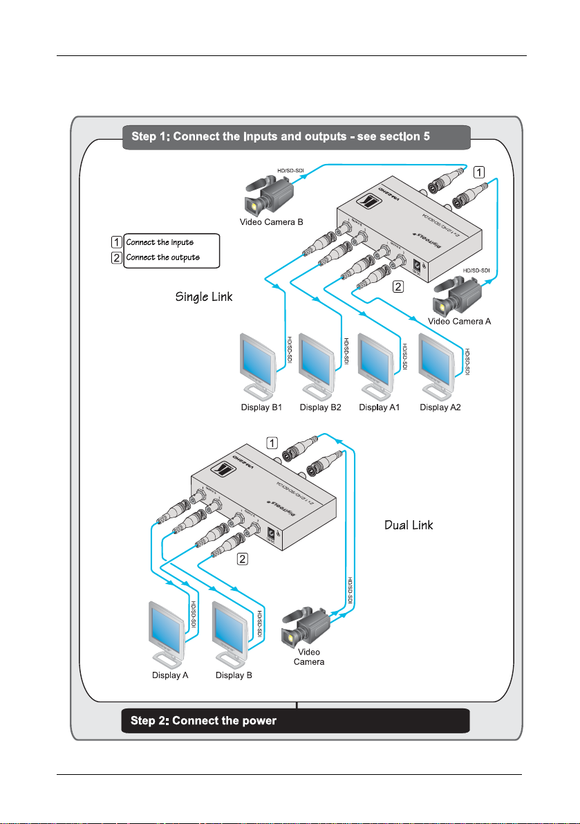
2.1 Quick Start
This quick start chart summarizes the basic setup and operation steps.
2
KRAMER: SIMPLE CREATIVE TECHNOLOGY
Page 5

Overview
3 Overview
The VM-22HD 2 x 1:2 HD/SD-SDI DA is a high-performance 2 x 1:2
distributor for all SDI video signals. In particular, the VM-22HD:
• Transmits up to 200m
• Accepts two inputs and distributes each signal to two pairs of
identical outputs using BNC connectors
• Has a video bandwidth of 1.485GHz that enables it to be used for
standard-definition and high-definition serial digital video signals
(SD/HD-SDI)
• Also passes digital information (embedded audio, Teletext, time
code, and so on) during the video blanking period
• SMPTE 292M, 259M, 344M, and 372M (dual link application)
compliance and data rates of 143, 177, 270, 360, 540, 1483.5, and
1485Mbps
• Provides automatic, multi-rate, equalization and reclocking to
compensate for losses typical to long runs of 75Ω co-axial cable
of up to 200m
• Has LEDs indicating the SDI resolution
To achieve the best performance:
• Use only good quality connection cables
1
to avoid interference,
deterioration in signal quality due to poor matching, and elevated
noise levels (often associated with low quality cables)
• Avoid interference from neighboring electrical appliances that
may adversely influence signal quality and position your Kramer
VM-22HD away from moisture, excessive sunlight and dust
1 Available from Kramer Electronics on our Web site at http://www.kramerelectronics.com
3
Page 6

Your VM-22HD 2 x 1:2 HD/SD-SDI DA
4 Your VM-22HD 2 x 1:2 HD/SD-SDI DA
Figure 1 and Table 1 define the unit.
Figure 1: VM-22HD 2 x 1:2 HD/SD-SDI DA
Table 1: VM-22HD 2 x 1:2 HD/SD-SDI DA Functions
# Feature Function
1 12V DC Connector +12V DC for powering the unit
2 OUTPUT A 2 BNC connector Connects to the SDI A acceptor 2
3 OUTPUT A 1 BNC connector Connects to the SDI A acceptor 1
4 OUTPUT B 2 BNC connector Connects to the SDI B acceptor 2
5 OUTPUT B 1 BNC connector Connects to the SDI B acceptor 1
6 INPUT A BNC connector Connects to the SDI A source
7 SD1/HD2 INPUT A LED Illuminates blue for the HD-SDI signal, green for the
8 SD/HD INPUT B LED Illuminates blue for the HD-SDI signal, green for the
9 INPUT B BNC connector Connects to the SDI B source
10 ON LED Illuminates green when receiving power
SD-SDI signal on input A
SD-SDI signal on input B
1 Standard Definition (SD) means an NTSC or PAL compatible video format, consisting of 480 (for NTSC) or 576 (for PAL)
lines of interlaced video; as well as 480 and 576 line progressive scan video format
2 High Definition (HD) means a video format, consisting of either 720 active lines of progressive video or 1080 lines of either
progressive or interlaced video
4
KRAMER: SIMPLE CREATIVE TECHNOLOGY
Page 7

Connecting the VM-22HD 2 x 1:2 HD/SD-SDI DA
5 Connecting the VM-22HD 2 x 1:2 HD/SD-SDI DA
This section describes how to connect the VM-22HD in single link mode
(see section 5.1
5.1 Connecting the VM-22HD in the Single Link Mode
) and in dual link mode (see section 5.2).
To
connect the VM-22HD, as shown in the example in Figure 2
1
following
:
, do the
1. Connect one or two HD-SDI/SD-SDI video sources (for example, cameras)
to the INPUT A and/or B BNC connectors.
2
2. Connect up to
four video OUTPUT BNC connectors to the appropriate
HD-SDI/SD-SDI video acceptors (for example, displays).
3. Connect the 12V DC power adapter to the power socket and connect the
adapter to the mains electricity (not shown in Figure 2
).
The VM-22HD operates as soon as it is connected and powered on.
Figure 2: Connecting the VM-22HD in Single Link Mode
1 Switch OFF the power on each device before connecting it to your VM-22HD. After connecting your VM-22HD, switch on
its power and then switch on the power on each device
2 You do not have to connect all outputs
5
Page 8

Connecting the VM-22HD 2 x 1:2 HD/SD-SDI DA
5.2 Connecting the VM-22HD in the Dual Link Mode
To connect the VM-22HD, as the example in Figure 3
following
1
:
illustrates, do the
1. Connect one HD-SDI/SD-SDI video source (for example, a dual-link
camera) to the INPUT A and B BNC connectors.
2. Connect OUTPUT A 1 and B 1 BNC connectors to a dual link
HD-SDI/SD-SDI video acceptor (for example, display A).
3. Connect OUTPUT A 2 and B 2 BNC connectors to a dual link
HD-SDI/SD-SDI video acceptor (for example, display B).
4. Connect the 12V DC power adapter to the power socket and connect the
adapter to the mains electricity (not shown in Figure 3
).
The VM-22HD operates as soon as it is connected and powered on.
Figure 3: Connecting the VM-22HD in Dual Link Mode
1 Switch OFF the power on each device before connecting it to your VM-22HD. After connecting your VM-22HD, switch on
its power and then switch on the power on each device
6
KRAMER: SIMPLE CREATIVE TECHNOLOGY
Page 9

Technical Specifications
6 Technical Specifications
The VM-22HD technical specifications are shown in Table 2:
Table 2: VM-22HD 2 x 1:2 HD/SD-SDI DA Technical Specifications1
INPUTS: 2 SMPTE-259M, 292M, 344M, 372M serial video inputs,
OUTPUTS: 4 equalized and reclocked SMPTE-259M, 292M, 344M, 372M
OUTPUT LEVEL:
COUPLING: AC
POWER SOURCE: 12V DC, 250mA
DIMENSIONS: 12cm x 7.2cm x 2.4cm (4. 7 " x 2.8" x 1.0") W, D, H
WEIGHT: 0.3kg (0.7lbs) approx.
ACCESSORIES: Power supply
OPTIONS: RK-3T 19” rack adapter
75Ω on BNC connectors
serial video outputs, 75Ω on BNC connectors
800mVpp /75Ω
1 Specifications are subject to change without notice
7
Page 10

LIMITED WARRANTY
Kramer Electronics (hereafter ) warrants this product free from defects in material and workmanship under the
following terms.
HOW LONG IS THE WARRANTY
Labor and parts are warranted for seven years from the date of the first customer purchase.
WHO IS PROTECTED?
Only the first purchase customer may enforce this warranty.
WHAT IS COVERED AND WHA T IS NO T COVERED
Except as below, this warranty c overs all defects in material or workmanship in this product. The f ollowing are not covered
by the warranty:
1. Any product which is not distributed by Kramer, or which is not purchased from an authorized Kramer dealer. If you are
uncertain as to whether a dealer is authorized, please contact Kramer at one of the agents listed in the Web site
www.kramerelectronics.com.
2. Any product, on which the serial number has been defaced, modified or removed, or on which the WARRANTY VOID
TAMPERED sticker has been torn,
IF reattached, removed or otherwise interfered with.
3. Damage, deterioration or malfunction resulting from:
i) Accident, misuse, abuse, neglect, fire, water, lightning or other acts of nature
ii) Product modificat ion, or f ailure to follow ins tructio ns suppl ied with th e product
iii) Repair or attempted repair by anyone not authorized by Kramer
iv) An y shipment of the product (claims must be presented to the carrier)
v) Removal or installation of the product
vi) Any other cause, which does not relate to a product defect
vii) Cartons, equipment enclosures, cables or accessories used in conjunction with the product
WHAT WE WILL PAY FOR AND WHAT WE WILL NOT PAY FOR
We will pay labor and material expenses for covered items. We will not pay for the following:
1. Removal or installations charges.
2. Co sts of initial technical adjustments (set-up), including adjustment of user controls or programming. These costs are the
responsibility of the Kramer dealer from whom the product was purchased.
3. Shipping charges.
HOW YOU CAN GET WARRANTY SERVICE
1. To obtain service on you product, you must take or ship it prepaid to any authorized Kramer service center.
2. Whenever warranty service is required, the original dated invoice (or a copy) must be presented as proof of warranty
coverage, and should be included in any shipment of the product. Please also include in any mailing a contact name,
company, address, and a description of the problem(s).
3. For the name of the nearest Kramer authorized service center, consult your authorized dealer.
LIMITATION OF IMPLIED WARRANTIES
All implied warranties, including warranties of merchantability and fitness for a particular purpose, are limited in duration to
the leng th of th is warra nty.
EXCLUSION OF DAMAGES
The liability of Kramer for any effective products is limited to the repair or replacement of the product at our option. Kramer shall
not be liable for:
1. Damage to other property caused by defects in this product, damages based upon inconvenience, loss of use of the product, loss
of time, commerc ial loss; or:
2. Any other damages, whether incidental, consequential or otherwise. Some countries may not allow limitations on how long an
implied warranty lasts and/or do not allow the exclusion or limitation of incidental or consequential damages, so the above
limitations and exclusions may not apply to you.
This warranty gives you specific legal rights, and you may also have other rights, which vary from place to place.
NOTE:
All products returned to Kramer for service must have prior approval. This may be obtained from your dealer.
This equipment has been tested to determine compliance with the requirements of:
EN-50081: "Electromagnetic compatibility (EMC);
Residential, commercial and light industry"
EN-50082: "Electromagnetic compatibility (EMC) generic immunity standard.
CFR-47: FCC* Rul es and Regulations:
CAUTION!
generic emission standard.
Part 1:
Part 1: Residential, commercial and light industry environment".
Part 15: “Radio frequency devices
Subpar t B Uninten tional radiators”
Servicing the machines can only be done by an authorized Kramer technician. Any user who makes changes or
modifications to the unit without the expressed approval of the manufacturer will void user authority to operate the
equipment.
Use the supplied DC power supply to feed power to the machine.
Please use recommended interconnection cables to connect the machine to other components.
* FCC and CE approved using STP cable (for twisted pair products)
Kramer
8
Page 11

For the latest information on our products and a list of Kramer
distributors, visit our Web site: www.kramerelectronics.com
where updat
es to this user manual may be found.
We welcome your questions, comments and feedback.
Safety Warning:
Disconnect the unit from the power supply before
opening/servicing.
Caution
Kramer Electronics, Ltd.
Web site: www.kramerelectronics.com
E-mail: info@kramerel.com
P/N: 2900-000353 REV 3
 Loading...