

Page 1

Kramer Electronics, Ltd.
USER MANUAL
Model:
VA-14
4x1 Balanced Audio Mixer
Page 2

Contents
Contents
1
Introduction 1
2
Getting Started 1
2.1 Quick Start 1
3
Overview 3
4
Your VA-14 4x1 Balanced Audio Mixer 4
5
Using Your VA-14 4x1 Balanced Audio Mixer 6
5.1 Connecting Your VA-14 4x1 Balanced Audio Mixer 6
5.2 Operating Your VA-14 4x1 Balanced Audio Mixer 8
6
Technical Specifications 8
Figures
Figure 1: VA-14 4x1 Balanced Audio Mixer 4
Figure 2: VA-14 4x1 Balanced Audio Mixer Underside Features 5
Figure 3: Connecting the VA-14 4x1 Balanced Audio Mixer 7
Tables
Table 1: VA-14 4x1 Balanced Audio Mixer Front Panel Features 4
Table 2: VA-14 4x1 Balanced Audio Mixer Rear Panel Features 4
Table 3: VA-14 4x1 Balanced Audio Mixer Underside Features 5
Table 4: Technical Specifications of the VA-14 4x1 Balanced Audio Mixer 8
i
Page 3

Introduction
1 Introduction
Welcome to Kramer Electronics (since 1981): a world of unique, creative and
affordable solutions to the infinite range of problems that confront the video,
audio and presentation professional on a daily basis. In recent years, we have
redesigned and upgraded most of our line, making the best even better! Our
500-plus different models now appear in 8 Groups1, which are clearly defined
by function.
Congratulations on purchasing your Kramer VA-14, which is ideal for:
Live stage and studio audio mixing
Presentation systems and press conferences
Post production in video/audio studios
The package includes the following items:
VA-14 4x1 Balanced Audio Mixer
Power adapter (12V DC Input)
This user manual2
2 Getting Started
We recommend that you:
Unpack the equipment carefully and save the original box and packaging
materials for possible future shipment
Review the contents of this user manual
Use Kramer high performance high resolution cables3
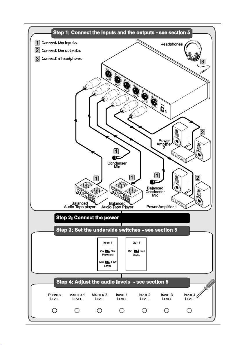
2.1 Quick Start
This quick start chart summarizes the basic setup and operation steps.
1 GROUP 1: Distribution Amplifiers; GROUP 2: Video and Audio Switchers, Matrix Switchers and Controllers; GROUP 3:
Video, Audio, VGA/XGA Processors; GROUP 4: Interfaces and Sync Processors; GROUP 5: Twisted Pair Interfaces;
GROUP 6: Accessories and Rack Adapters; GROUP 7: Scan Converters and Scalers; and GROUP 8: Cables and Connectors
2 Download up-to-date Kramer user manuals from the Internet at this URL: http://www.kramerelectronics.com
3 The complete list of Kramer cables is on our Web site at http://www.kramerelectronics.com
1
Page 4
Getting Started
2
KRAMER: SIMPLE CREATIVE TECHNOLOGY
Page 5

Overview
3 Overview
The VA-14 4x1 Balanced Audio Mixer is a high quality, low noise, 4-input
balanced audio standalone mixer that provides for two different levels on
each input - Mic level or line level, as well as the selection of either a
dynamic or phantom microphone.
The VA-14 includes:
Four rear panel XLR input connectors and two XLR output connectors
A front panel headphone output, positioned alongside a phones level
potentiometer
Two master front panel potentiometers for adjusting each of the master
outputs of all1 channels
Four front panel level potentiometers3 for adjusting each input
A 12 VDC rear panel power socket, which is ideal for field use2. The unit
generates broadcast voltage level ±15V and ±48V internally from the
single 12 VDC input
Underside panel switches3 for selecting the balanced level (Mic or line)
Underside panel switches3 for applying 48V phantom power4
Achieving the best performance means:
Connecting only good quality connection cables, thus avoiding
interference, deterioration in signal quality due to poor matching, and
elevated noise levels (often associated with low quality cables)
Avoiding interference from neighboring electrical appliances that may
adversely influence signal quality and positioning your VA-14 in a
location free from moisture and away from excessive sunlight and dust
Caution – No operator-serviceable parts inside unit.
Warning – Use only the Kramer Electronics input power
wall adapter that is provided with this unit5.
Warning – Disconnect power and unplug unit from wall
before installing or removing device or servicing unit.
1 The combined signals from inputs 1 to 4 are mixed
2 Via a belt battery, for example
3 Each corresponds to its respective input
4 This is for applications that require typical condenser microphones to be connected directly to the VA-14. To prevent
unnecessary damage, apply phantom power to the Mic only when required
5 For example: model number AD2512C, part number 2535-000251
3
Page 6

Your VA-14 4x1 Balanced Audio Mixer
4 Your VA-14 4x1 Balanced Audio Mixer
Figure 1, Table 1 and Table 2 define the VA-14 4x1 Balanced Audio Mixer.
Figure 1: VA-14 4x1 Balanced Audio Mixer
Table 1: VA-14 4x1 Balanced Audio Mixer Front Panel Features
# Feature Function
1 POWER Switch Illuminated switch for turning the unit ON or OFF
2 PHONES OUT 6.5mm Connector Connect to the headphone set
3 PHONES LEVEL Potentiometer Adjusts the headphone volume
4 MASTER LEVEL Potentiometer Adjusts the combined signals from all inputs mixed to the output
(from 1 to 2)
5 INPUT LEVEL Potentiometer Adjusts the input level (from 1 to 4)
Table 2: VA-14 4x1 Balanced Audio Mixer Rear Panel Features
# Feature Function
6 INPUT XLR Female Connectors Connect to the audio source (from 1 to 4)
7 OUT XLR Male Connectors Connect to the audio acceptor (from 1 to 2)
8 12V DC +12V DC connector for powering the unit
4
KRAMER: SIMPLE CREATIVE TECHNOLOGY
Page 7

Your VA-14 4x1 Balanced Audio Mixer
Figure 2 and Table 3 define the underside of the VA-14 4x1 Balanced Audio
Mixer:
Figure 2: VA-14 4x1 Balanced Audio Mixer Underside Features
Table 3: VA-14 4x1 Balanced Audio Mixer Underside Features
# Feature Function
1 PHANTOM Move to ON to select a phantom microphone; move to OFF to
INPUT
(from 1 to 4)
2
3 OUT LEV EL Move to MIC to select a microphone level output; move to LINE
LEVEL Move to MIC to select a microphone level input; move to LINE to
select a dynamic microphone
select a LINE level input
to select a LINE level output (from 1 to 2)
5
Page 8

Using Your VA-14 4x1 Balanced Audio Mixer
5 Using Your VA-14 4x1 Balanced Audio Mixer
Sections 5.1 and 5.2 describe how to connect and operate your balanced audio
mixer, respectively.
5.1 Connecting Your VA-14 4x1 Balanced Audio Mixer
To connect up to four balanced audio sources to the VA-14 4x1 Balanced
Audio Mixer unit, as the example in Figure 3 illustrates, do the following:
1. Connect a balanced audio source (for example, a condenser microphone)
to the XLR female:
INPUT 1 connector
INPUT 3 connector
On the underside set the INPUT 1 and INPUT 3:
PHANTOM switches to ON
LEVEL switches to MIC
2. Connect a balanced audio source (for example, a balanced audio tape
player) to XLR female:
INPUT 2 connector
INPUT 4 connector
On the underside set the INPUT 2 and INPUT 4:
PHANTOM switches to OFF
LEVEL switches to LINE
3. Connect each of the XLR male OUTPUT 1 and OUTPUT 2 connectors
to two power amplifiers, and connect each power amplifier to a pair of
speakers.
On the machine underside, set the OUT 1and OUT 2 switches to LINE.
4. Connect the PHONES OUTPUT connector to a headphone set.
5. Connect the 12V DC power adapter to the power socket and connect the
adapter to the mains electricity.
For every unused input, be sure to rotate the LEVEL potentiometer fully
counter-clockwise (to the minimum level)
6
KRAMER: SIMPLE CREATIVE TECHNOLOGY
Page 9

Using Your VA-14 4x1 Balanced Audio Mixer
Figure 3: Connecting the VA-14 4x1 Balanced Audio Mixer
7
Page 10

Technical Specifications
5.2 Operating Your VA-14 4x1 Balanced Audio Mixer
On the VA-14xl 4x1 Balanced Audio Mixer unit, you can adjust the level:
From a specific1 input, by rotating the appropriate LEVEL potentiometer
From all the inputs mixed together, by rotating each of the MASTER
potentiometers (1 and 2) respectively
At the headphone set, by rotating the PHONES LEVEL potentiometer
6 Technical Specifications
Table 4: Technical Specifications2 of the VA-14 4x1 Balanced Audio Mixer
INPUTS: 4 balanced audio, Line or Mic, on female XLR connectors
OUTPUTS:
MAX. OUTPUT LEVEL: Line: 20Vpp; Phones: 4.5Vpp; Mic: 300mVpp
BANDWIDTH (-3dB): > 40 kHz
S/N RATIO: Mic in, Phones Out: 45.3dB
CROSSTALK (all hostile): Mixed inputs
CONTROLS: Line In, Line Out: <-57dB to -14.3dB
COUPLING: In: AC; out: bal line/mic – DC; phones, AC
AUDIO THD + NOISE: Line In, Line Out: 0.007%; Mic In, Line Out: 0.15%
AUDIO 2nd HARMONIC: Line In, Line Out: 0.001%; Mic In, Line Out: 0.005%
POWER SOURCE: 12 V, 250mA DC
DIMENSIONS: 21.5cm x 16.2cm x 4.4cm (8.46" x 6.38" x 1.73"), W, D, H
WEIGHT: 1.4 kg. (3.1 lbs.) approx.
ACCESSORIES: Power supply
OPTIONS: 19" rack adapter
2 audio, balanced on a male XLR connector
One headphone output on a 6.5mm connector
Line In, Phones Out: 83.3dB
Line In, Line Out: 84.3dB
Mic In, Line Out: 64dB
Mic In, Line Out; <0dB to 60.5dB
Line In, Phones Out: <-47dB to -18dB
Mic In, Phones Out: <0dB to 58.9dB
In level and master/phones level, min to max position for both
Line In, MIC OUT range: <-50dB to -25dB
Mic In, Mic Out range:<0dB to 21.6dB
Underside slide switches: inputs: Line/Mic and +48V phantom ON/OFF
Outputs: Line/Mic
Line In, Phones Out: 0.085%
Mic In, Phones Out: 0.38%
Line In, Phones Out: 0.009%; Mic In, Phones Out: 0.024%
1 For example, rotating the LEVEL potentiometer 2 will adjust the volume generated to the speakers via the power amplifier
from the balanced audio source 2
2 Specifications are subject to change without notice
8
KRAMER: SIMPLE CREATIVE TECHNOLOGY
Page 11

Kramer Electronics (hereafter ) warrants this product free from defects in material and workmanship under the
The liability of Kramer for any effective products is limited to the repair or replacement of the product at our option. Kramer shall
Except as below, this warranty covers all defects in material or workmanship in this product. The following are not covered
uncertain as to whether a dealer is authorized, please contact Kramer at one of the agents listed in the Web site
LIMI TED WARR ANTY
following terms.
HOW LONG IS THE WARRA NTY
Labor and parts are warranted for seven years from the date of the first customer purchase.
WHO IS PROTECT ED?
Only the first purchase customer may enforce this warranty.
WHAT IS COVERED AND WHAT IS NOT COVERED
Kramer
by the warranty:
1. Any product which is not distributed by Kramer, or which is not purchased from an authorized Kramer dealer. If you are
www.kramerelectronics.com.
2. Any product, on which the serial number has been defaced, modified or removed.
3. Damage, deterioration or malfunction resulting from:
i) Accident, misuse, abuse, neglect, fire, water, lightning or other acts of nature
ii) Product modification, or failure to follow instructions supplied with the product
iii) Repair or attempted repair by anyone not authorized by Kramer
iv) Any shipment of the product (claims must be presented to the carrier)
v) Removal or installation of the product
vi) Any other cause, which does not relate to a product defect
vii) Cartons, equipment enclosures, cables or accessories used in conjunction with the product
WHAT WE WILL PAY FOR AN D WHAT WE WILL NOT PAY F OR
We will pay labor and material expenses for covered items. We will not pay for the following:
1. Removal or installations charges.
2. Costs of initial technical adjustments (set-up), including adjustment of user controls or programming. These costs are the
responsibility of the Kramer dealer from whom the product was purchased.
3. Shipping charges.
HOW YOU CAN G ET WAR RANTY SERVICE
1. To obtain service on you product, you must take or ship it prepaid to any authorized Kramer service center.
2. Whenever warranty service is required, the original dated invoice (or a copy) must be presented as proof of warranty
coverage, and should be included in any shipment of the product. Please also include in any mailing a contact name,
company, address, and a description of the problem(s).
3. For the name of the nearest Kramer authorized service center, consult your authorized dealer.
LIMI TATION OF IM PLIED WARRAN TIES
All implied warranties, including warranties of merchantability and fitness for a particular purpose, are limited in duration to
the length of this warranty.
EXCLUSIO N O F DAMAGES
not be liable for:
1. Damage to other property caused by defects in this product, damages based upon inconvenience, loss of use of the product, loss
of time, commercial loss; or:
2. Any other damages, whether incidental, consequential or otherwise. Some countries may not allow limitations on how long an
implied warranty lasts and/or do not allow the exclusion or limitation of incidental or consequential damages, so the above
limitations and exclusions may not apply to you.
This warranty gives you specific legal rights, and you may also have other rights, which vary from place to place.
All products returned to Kramer for service must have prior approval. This may be obtained from your dealer.
NOTE:
This equipment has been tested to determine compliance with the requirements of:
EN-50081: "Electromagnetic compatibility (EMC);
Residential, commercial and light industry"
EN-50082: "Electromagnetic compatibility (EMC) generic immunity standard.
CFR-47: FCC Rules and Regulations:
CAUT ION!
generic emission standard.
Part 1:
Part 1: Residential, commercial and light industry environment".
Part 15: “Radio frequency devices
Subpart B Unintentional radiators”
Servicing the machines can only be done by an authorized Kramer technician. Any user who makes changes or
modifications to the unit without the expressed approval of the manufacturer will void user authority to operate the
equipment.
Use the supplied DC power supply to feed power to the machine.
Please use recommended interconnection cables to connect the machine to other components.
9
Page 12

For the latest information on our products and a list of Kramer
distributors, visit our Web site: www.kramerelectronics.com,
where updates to this user manual may be found.
We welcome your questions, comments and feedback.
Safety Warning:
Disconnect the unit from the power supply before
opening/servicing.
Caution
Kramer Electronics, Ltd.
Web site: www.kramerelectronics.com
E-mail: info@kramerel.com
P/N: 2900-000314 REV 1
 Loading...