

Page 1

Kramer Electronics, Ltd.
Preliminary
USER MANUAL
Model:
TP-9, Audio/Video Line Transmitter
TP-10, Audio/Video Line Receiver
Page 2

Contents
Contents
1 Introduction 1
2 Getting Started 1
2.1 Quick Start 2
3 Overview 3
3.1 About the Power Connect Feature 4
3.2 Shielded Twisted Pair (STP)/Unshielded Twisted Pair (UTP) 4
4 Your Audio/Video Line Transmitter and Line Receiver 5
4.1 Your TP-9 Audio/Video Line Transmitter 5
4.2 Your TP-10 Audio/Video Line Receiver 7
5 Connecting an Audio/Video Distribution System 8
5.1 Wiring the CAT 5 LINE IN/LINE OUT RJ-45 Connectors 10
6 Technical Specifications 11
Figures
Figure 1: TP-9 Audio/Video Line Transmitter 5
Figure 2: TP-9 Audio/Video Line Transmitter Underside 6
Figure 3: TP-10 Audio/Video Line Receiver 7
Figure 4: Connecting the IR Emitter 8
Figure 5: Audio/Video Distribution System up to 300ft (100m) UTP Cable 9
Figure 6: CAT 5 PINOUT 10
Tables
Table 1: Features and Functions of the TP-9 5
Table 2: TP-9 Audio/Video Line Transmitter Underside Features 6
Table 3: Features and Functions of the TP-10 7
Table 4: CAT 5 PINOUT 10
Table 5: Technical Specifications of the TP-9/TP-10 11
i
Page 3

Introduction
1 Introduction
Welcome to Kramer Electronics! Since 1981, Kramer Electronics has been
providing a world of unique, creative, and affordable solution s to the vast
range of problems that confront the video, audio, presentation, and
broadcasting professional on a daily basis. In recent years, we have
redesigned and upgraded most of our line, making the best even better! Our
1,000-plus different models now appear in 11 groups
defined by function.
Thank you for purchasing the Kramer TOOLS TP-9 Audio/Video Line
Transmitter and Kramer TOOLS TP-10 Audio/Video Line Receiver that are
ideal for high-quality home cinema installations.
The TP-9 and TP-10 uses existing UTP cabling for an efficient, fast and
uncluttered environment in:
• Studios, airports, offices and hospitals
• Security and military applications
The package includes the following items:
• TP-9 and/or TP-10
• Two sets of IR emitter cables
2
• Power supply (12V DC)
• This user manual
3
1
that are clearly
2 Getting Started
We recommend that you:
• Unpack the equipment carefully and save the original box and
packaging materials for possible future shipment
• Review the contents of this user manual
• Use Kramer high performance high-resolution cables
4
1 GROUP 1: Distribution Amplifiers; GROUP 2: Switchers and Matrix Switchers; GROUP 3: Control Systems;
GROUP 4: Format/Standards Converters; GROUP 5: Range Extenders and Repeaters; GROUP 6: Specialt y AV Products;
GROUP 7: Scan Converters and Scalers; GROUP 8: Cables and Connectors; GROUP 9: Room Connectivity;
GROUP 10: Accessories and Rack Adapters; GROUP 11: Sierra Products
2 3.5mm to IR Emitter Control Cable (C-A35/IRE-10)
3 Download up-to-date Kramer user manuals from our Web site at http://www.kramerelectronics.com
4 The complete list of Kramer cables is on our Web site at http://www.kramerelectronics.com
1
Page 4
Getting Started
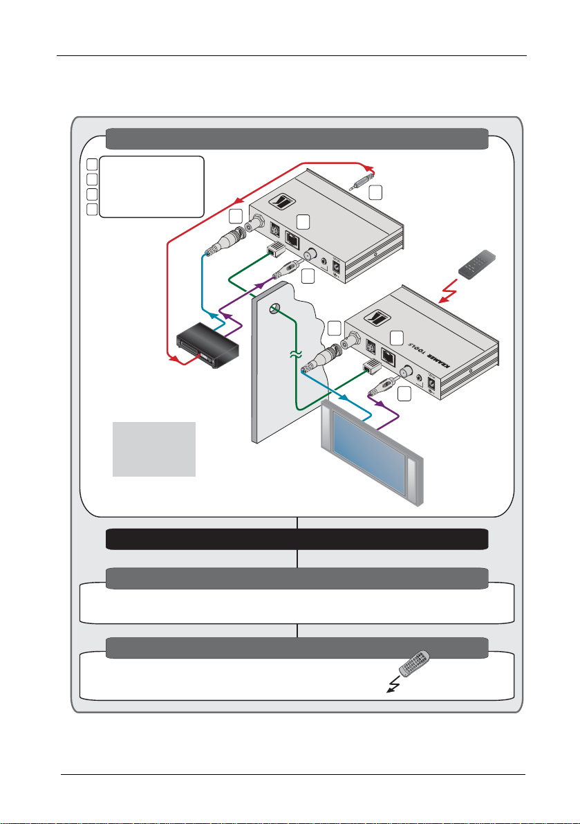
2.1 Quick Start
This quick start chart summarizes the basic setup and operation:
Step 1: Connect the inputs and outputs - see section 5
Connect the inputs
Connect the inputs
1
Connect the outputs
Connect the outputs
2
Connect the IR remote cable
Connect the IR remote cable
3
Connect the CAT 5 cable
Connect the CAT 5 cable
4
Set the AUDIO and
Set the AUDIO and
VIDEO underside
VIDEO underside
switches
switches
appropriately
appropriately
CV
IR
Video Player
1
Audio
CV IN
TP-9
4
Y/C IN
S/PDIF
LO
INE
UT
A
NALOG
AIN
UDIO
1
3
TP-9
2
CV O
UT
Y/C O
UT
CV
Plasma
Display
Audio/VideoLine Transmitter
LIN
INE
Audio
TP-10
4
S/PDIF
AO
UDIO UT
2
Position the IR
Position the IR
sensor window in
sensor window in
the line-of-sight
the line-of-sight
of the remote
of the remote
controller
controller
IR
A
NALOG
TP-10
Audio/VideoLine Receiver
Step : Connect the power2Step : Connect the power2
Step 3: Adjust the trimmers
Adjust the EQ. and LEVEL trimmers on the TP-10 if required, by
Adjust the EQ. and LEVEL trimmers on the TP-10 if required, by
inserting a screwdriver into the small hole and rotating it carefully
inserting a screwdriver into the small hole and rotating it carefully
Step 4: Operation
Operate via the remote controller
LOCK
GROUP
VOL--V
V
L+VO
RCL
STO
TRANS
2
KRAMER: SIMPLE CREATIVE TECHNOLOGY
Page 5

Overview
3 Overview
Using the TP-9 Audio/Video Line Transmitter with the TP-10 Audio/Video
Line Receiver constitutes an Audio/Video Line transmitter/receiver system.
The TP-9 accepts the audio and video input signals, encodes and sends
them to the CAT 5 cable. The TP-10 receives the CAT 5 signal, which
includes both audio and video, decodes and distributes it to the audio and
video acceptors. The IR signal from the remote control is transmitted from
the TP-10, via the CAT 5 cable to the TP-9, which is connected to a video
source, letting you control the video source via its remote control
transmitter from a distance.
The TP-9 Audio/Video Line Transmitter includes:
• A composite video input on a BNC connector and an s-Video (Y/C)
input on a 4-pin connector
• A digital audio input (S/PDIF) and an analog stereo audio input
• IR emitter outputs for up to two machines
• A CAT 5 LINE OUT RJ-45 connector for signal transmission to the
TP-10 and IR reception
The TP-10 Audio/Video Line Receiver includes:
• A composite video output on a BNC connector and an s-Video (Y/C)
output on a 4-pin connector
• A digital audio output (S/PDIF) and an analog stereo audio output
• An IR sensor
• A CAT 5 LINE IN RJ-45 connector for signal reception from the TP-9
and IR transmission
• Level and EQ. controls for the CV and Y/C signals
Kramer twisted pair adapters are an excellent way to solve remote
controlling requirements without using more costly coaxial cable or fiber, or
wireless transmission systems.
To achieve the best performance:
• Connect only good quality connection cables, thus avoiding
interference, deterioration in signal quality due to poor matching, and
elevated noise levels (often associated with low quality cables)
• Avoid interference from neighboring electrical appliances that may
adversely influence signal quality and position your Kramer TP-9
and/or TP-10 away from moisture, excessive sunlight and dust
3
Page 6

Overview
3.1 About the Power Connect Feature
The Power Connect feature applies as long as the cable can carry power.
This feature is available when using STP cable and the distance does not
exceed 50m on standard CAT 5 cable. For longer distances, heavy gauge
cable should be used
1
. For units which are connected via RJ-45 connectors,
make sure that the shield of the STP cable is connected to the metal casing
of the connectors on both ends of the cable. For units which are connected
via terminal block connectors, the shield of the STP cable must be
connected to a ground terminal on the units at both ends (use the ground
terminal of the power supply connection if necessary).
For a CAT 5 cable exceeding a distance of 50m, separate power suppli es
should be connected to the transmitter and to the receiver simultaneously.
3.2 Shielded Twisted Pair (STP)/Unshielded Twisted Pair (UTP)
recommend that you use Shielded Twisted Pair (STP) cable. There are
We
different levels of STP cable available, and we advise you to use the best
quality STP cable that you can afford. Our non-skew-free cable, Kramer
BC-STP is intended for analog signals where skewing is not an issue. For
cases where there is skewing, our UTP skew-free cable, Kramer BC-XTP,
may be used. Bear in mind, though, that we advise using STP cables where
possible, since the compliance to electromagnetic interference was tested
using those cables.
Although Unshielded Twisted Pair (UTP) cable might be preferred for long
range applications, the UTP cable should be installed far away from electric
cables, motors and so on, which are prone to cre ate electrical interference.
However, since the use of UTP cable might cause inconform ity to
electromagnetic standards, Kramer does not commit to meeting the standard
with UTP cable.
1 CAT 5 cable is still suitable for the video/audio transmission, but not for feeding the power at these distances
4
KRAMER: SIMPLE CREATIVE TECHNOLOGY
Page 7

Your Audio/Video Line Transmitter and Line Receiver
4 Your Audio/Video Line Transmitter and Line Receiver
This section describes the:
• TP-9 Audio/Video Line Transmitter, see section 4.1
• TP-10 Audio/Video Line Receiver, see section 4.2
4.1 Your TP-9 Audio/Video Line Transmitter
Figure 1
6
and Table 1 define the TP-9 unit:
5
4
3
7
8
1
2
10
9
2
1
3
4
7
8
Figure 1: TP-9 Audio/Video Line Transmitter
Table 1: Features and Functions of the TP-9
# Feature Function
1 CV IN BNC Connector Connects to the composite video source
2 Y/C IN 4-pin Connector Connects to the s-Video source
3 LINE OUT RJ-45 Connector Connects to the LINE IN connector on t he TP-101
4
5 ANALOG 3.5mm Mini connector Connects to the analog audio sour ce
6
7
8 3.5mm Mini connector 2
9 IR LINK LED Lights when an IR link is established
10 ON LED Lights when receiving power
S/PDIF RCA Connector Connects to the digital audio source
IN
AUDIO
12V DC
3.5mm Mini connector 1 Connects to the IR emitter cable
IR
OUT
+12V DC connector for powering the unit
5
6
10
9
1 Using a straight pin to pin UTP cable with RJ-45 connectors at both ends (the PINOUT is defined in Table 4 and Figure 6)
5
Page 8

Your Audio/Video Line Transmitter and Line Receiver
Figure 2 and Table 2 define the switches on the underside of the TP-9:
Figure 2: TP-9 Audio/Video Line Transmitter Underside
Table 2: TP-9 Audio/Video Line Transmitter Underside Features
# Feature Function
1
VIDEO Input Selector
Switch
2
AUDIO Input Selector
Switch
CV Set to CV to transmit composite video
Y/C Set to Y/C to transmit s-Video
S/PDIF
ANALOG
Set to S/PDIF to transmit digital audio
Set to ANALOG to transmit analog audio
6
KRAMER: SIMPLE CREATIVE TECHNOLOGY
Page 9

Your Audio/Video Line Transmitter and Line Receiver
4.2 Your TP-10 Audio/Video Line Receiver
Figure 3
and Table 3 define the TP-10 unit:
4
5
6
8
7
3
2
1
13
1
7
3
2
8
9
Figure 3: TP-10 Audio/Video Line Receiver
Table 3: Features and Functions of the TP-10
# Feature Function
1 CV OUT BNC Connector Connects to the composite video acceptor
2 Y/C OUT 4-pin Connector Connects to the s-Video acceptor
3 LINE IN RJ-45 Connector Connects to the LINE OUT connector on the TP-91
4
5 ANALOG 3.5mm Mini
6
7
8 IR LED Illuminates when receiving signals from an IR remote
9
10
11 LEVEL Trimmer2 Adjusts3 composite video output signal or Y output signal
12 C LEVEL Trimmer2 Adjusts3 the C output signal
13 ON LED Lights when receiving power
S/PDIF RCA
Connector
OUT
AUDIO
connector
12V DC
AV LED Illuminates when receiving the correct input signal
LINK
IR SENSOR
EQ. Trimmer2 Adjusts3 the video EQ. (equalization) compensation
CV/Y
Connects to the digital audio acceptor
Connects to the analog audio acceptor
+12V DC connector for powering the unit
control transmitter
IR sensor red glass window
10
6
5
4
11
12
13
1 Using a straight pin to pin UTP cable with RJ-45 connectors at both ends (the PINOUT is defined in Table 4 and Figure 6)
2 If necessary (for example, when using a long cable), the adjustment range may be improved b y opening the TP-10 cover
and shorting the following jumpers: J9, for equalization, J7, for CV or Y levels, and J8, for C level
3 Insert a screwdriver into the small hole and carefully rotate it, trimming the level
7
Page 10

Connecting an Audio/Video Distribution System
5 Connecting an Audio/Video Distribution System
To configure a TP-9/TP-10 audio/video distribution system (for example,
for high quality home cinema system), as Figure 5
1. On the TP-9 connect:
A composite video source (for example, a video player) to the CV
IN BNC connector
A digital audio source (for example, the video player’s audio
signal) to the AUDIO IN S/PDIF RCA connector
The IR OUT 2, 3.5mm mini connector to the IR receiver
video player) via the IR emitter cable (see Figure 4
2. On the TP-10, connect the:
CV OUT BNC connector to a composite video acceptor (for
example, a plasma display)
AUDIO OUT S/PDIF (digital audio) RCA connector
acceptor (for example, the plasma display’s audio connector)
3. Connect the LINE OUT connector of the TP-9 to the LINE IN connector of
the TP-10, via UTP cabling (maximum range of up to 300ft (100m )).
4. On the TP-9 underside, set the VIDEO switch to CV and the AUDIO
switch to S/PDIF.
Note: Do not power the device ON when set to S/PDIF. First set the device
to Analog mode, power on and then switch to S/PDIF if nee ded.
5. On each TP-9/TP-10 unit, connect a 12V DC power adapter to the power
socket and connect the adapter to the mains electricity (see section 3.1
6. On the TP-10, if required, adjust the CV EQ. and level, by inserting a
screwdriver into the small hole and carefully rotating it.
IR Emit te r
illustrates, do the following:
)
2
1
(on the
to an audio
).
Figure 4: Connecting the IR Emitter
1 Stick the IR emitter to the IR receiver window (usually located on the front panel of the video player)
2 You can also connect either the AUDIO OUT ANALOG 3.5mm mini connector to an analog audio acceptor, or both
AUDIO OUT connectors
8
KRAMER: SIMPLE CREATIVE TECHNOLOGY
Page 11

Connecting an Audio/Video Distribution System
Be sure to place the TP-10 in such a way that the IR SENSOR window will be
in the line-of-sight of your IR remote controller.
You can now operate the video player via its IR remote controller from a
distance.
TP-9
CV
Audio
IR
Video Player
CV IN
Y/C IN
LO
INE
S/PDIF
UT
A
NALOG
AIN
UDIO
Audio/Video Line Transmitter
TP-9
TP-10
CV O
UT
Y/C O
UT
LIN
INE
S/PDIF
AO
UDIO UT
A
NALOG
IR
Audio/Video Line Receiver
TP-10
CV
Audio
Plasma
Display
Figure 5: Audio/Video Distribution System up to 300ft (100m) UTP Cable
9
Page 12

Connecting an Audio/Video Distribution System
5.1 Wiring the CAT 5 LINE IN/LINE OUT RJ-45 Connectors
Table 4
and Figure 6 define the CAT 5 PINOUT, using a straight pin-to-pin
cable with RJ-45 connectors:
Table 4: CAT 5 PINOUT
EIA /TIA 568A EIA /TIA 568B
PIN Wire Color PIN Wire Color
1 Green/White 1 Orange/White
2 Green 2 Orange
3 Orange/White 3 Green/White
4 Blue 4 Blue
5 Blue/White 5 Blue/White
6 Orange 6 Green
7 Brown/White 7 Brown/White
8 Brown 8 Brown
Pair 1 4 and 5 Pair 1 4 and 5
Pair 2 3 and 6 Pair 2 1 and 2
Pair 3 1 and 2 Pair 3 3 and 6
Pair 4 7 and 8 Pair 4 7 and 8
Figure 6: CAT 5 PINOUT
10
KRAMER: SIMPLE CREATIVE TECHNOLOGY
Page 13

Technical Specifications
6 Technical Specifications
Table 5 defines the technical specifications1:
Table 5: Technical Specifications2 of the TP-9/TP-10
TP-9 TP-10
INPUTS:
OUTPUTS: 1 RJ-45 CAT-5 shielded connector
VIDEO Specifications
MAX. OUTPUT LEVEL: 2.6V
BANDWIDTH:
NON-LINEARITY: <0.05%
DIFF. GAIN: <0.05%
DIFF. PHASE: 0.09Deg
S/N RATIO: >75dB RMS/5MHz weighted
AUDIO Specifications
MAX. OUTPUT LEVEL: 0dBu
BANDWIDTH: 20Hz to 20kHz/0.1dB
CONVERSION SAMPLE RATE: 48kHz
CONVERSION RESOLUTION: 24 bits
S/N RATIO: >73dB
POWER SOURCE: 12V DC, 95mA 12V DC, 82mA
DIMENSIONS: 12cm x 6.95cm x 2.76cm (4.7" x 2.8" x 1.08") W, D, H
WEIGHT: 0.3 kg (0.67 lbs.) approx
ACCESSORIES: Power Supply, 3.5mm to IR Emitter Control Cable (C-A35/IRE-10)
OPTIONS: 15m (50ft) cable and 20m (65ft) IR Emitter Extension Cables
1 composite video 1Vpp/75Ω on a
BNC connector
1 s-Video 1Vpp/75Ω [Y], 0.3Vpp/75Ω
[C] on a 4-pin connector
1 S/PDIF (digital audio) on an RCA
connector
1 audio (analog audio) <0dBu on a
3.5mm mini connector
(LINE OUT)
2 IR emitters on 3.5mm mini
connectors
≥70MHz/-3dB
1 RJ-45 CAT-5 shielded connector (LINE IN)
1 composite video 1Vpp/75Ω on a BNC
connector
1 s-Video 1Vpp/75Ω [Y], 0.3Vpp/75Ω [C] on a
4-pin connector
1 S/PDIF (digital audio) on an RCA connector
1 audio (analog audio) <8dBu on a 3.5mm
mini connector
1 Specifications for 100m of CAT 5 UTP cable, unless otherwise specified
2 Specifications are subject to change without notice
11
Page 14

LIMITED WARRANTY
Kramer Electronics (hereafter ) warrants this product free from defects in material and workmanship under the
following terms.
HOW LONG IS THE W ARRANTY
Labor and parts are warranted for seven years from the date of the first customer purchase.
WHO IS PROTECTED?
Only the first purchase customer may enforce this warranty.
WHAT IS COVERED AND WHAT IS NOT COVERED
Except as below, this warranty covers all defects in material or workmanship in this product. The following are not covered
by the warranty:
1. Any product which is not distributed by Kramer, or which is not purchased from an authorized Kramer dealer. If you are
uncertain as to whether a dealer is authorized, please contact Kramer at one of the agents listed in the Web site
www.kramerelectronics.com.
2. Any product, on which the serial number has been defaced, modified or removed, or on which the WARRANTY VOID
TAMPERED sticker has been torn,
IF reattached, removed or otherwise interfered with.
3. Damage, de teriorat ion or ma lfunction resulti ng from:
i) Accident, misuse, abuse, neglect, fire, water, lightning or other acts of nature
ii) Product m odificati on, or fai lure to foll ow instru ctions sup plied wit h the produ ct
iii) Repair or attemp ted repai r by anyone not auth orized by Kramer
iv) Any shipment o f the product (clai ms mus t be pr esente d to th e carri er)
v) Removal or inst allation of the produ ct
vi) Any other ca use, which does n ot relate t o a produc t defect
vii) Cartons, equipment enclosures, cables or accessories used in conjunction with the product
WHAT WE WILL PA Y FOR AND WHA T WE WILL NOT PA Y FOR
W e will pay l abor and m aterial e xpenses for cove red items. W e wi ll not pay f or the foll owing:
1. Removal or inst alla tions char ges.
2. Costs of initial technical adjustments (set-up), including adjustment of user controls or programming. These costs are the
responsi bility of the Kram er deal er from wh om the pro duct w as purcha sed.
3. Shipping charges.
HOW YOU CAN GET WARRANTY SERVICE
1. To obtain service on you product, you must take or ship it prepaid to any authorized Kramer service center.
2. Whenever warranty service is required, the original dated invoice (or a copy) must be presented as proof of warranty
coverage, and should be included in any shipment of the product. Please also include in any mailing a contact name,
company, address, and a description of the problem(s).
3. For the name of the nearest Kramer authorized service center, consult your authorized dealer.
LIMITATION OF IMPLIED WARRANTIES
All implied warranties, including warranties of merchantability and fitness for a particular purpose, are limited in duration to
the length of this warranty.
EXCLUSION OF DAMAGES
The li abil ity o f K rame r for an y ef fec tive pr oduc ts is lim ite d to the repa ir or repl ac eme nt of the pro du ct at ou r o ptio n. Kra mer shall
not be liabl e for:
1. Damage to other p roperty ca used by def ects in this prod uct, dama ges based upon inco nvenien ce, loss o f use of the pro duct, l oss
of time, commercial loss; or:
2. Any other dam ages , whe ther inci den tal, c onseq uen tial o r oth erwi se. Some co untri es may no t all ow li mita tion s on how l ong an
implied warranty lasts and/or do not allow the exclusion or limitation of incidenta l or consequential damages, so the above
limitati ons and ex clusio ns may no t apply to you.
This warranty gives you specific legal rights, and you may al so have other rights, which vary from place to place.
NOTE:
All products re turned t o Krame r for ser vice mus t have pri or approv al. Th is may b e obtaine d from you r deale r.
This equipment has been tested to determine compliance with the requirements of:
EN-50081: "Electromagnetic compatibility (EMC);
Residential, commercial and light industry"
EN-50082: "Electromagnetic compatibility (EMC) generic immunity standard.
CFR-47: FCC* Rules and Regulations:
CAUTION!
generic em ission standar d.
Part 1:
Part 1: Residential, commercial and light industry environment".
Part 15: “Radio frequency de vices
Subpart B Uninte ntional radiators”
Servicing the machines can only be done by an authorized Kramer technician. Any user who makes changes or
modifications to the unit without the expressed approval of the manufacturer will void user authority to operate the
equipment.
Use the supplied DC power supply to feed power to the machine.
Please use recommended interconnection cables to connect the machine to other components.
* FCC and CE approved u sing STP c able (for tw isted pair products)
Kramer
12
KRAMER: SIMPLE CREATIVE TECHNOLOGY
Page 15

For the latest information on our products and a list of Kramer
distributors, visit our Web site: www.kramerelectronics.com,
where updates to this user manual may be found.
We welcome your questions, comments and feedback.
Safety Warning:
Disconnect the unit from the power supply before
opening/servicing.
Caution
P/N:
2900- 000144
Rev:
3
Kramer Electronics, Ltd.
Web site: www.kramerelectronics.com
E-mail: info@kramerel.com
P/N: 2900-000144 REV 3
 Loading...